

Ekinex 71 Series, EK-E12-TP Series, EK-E12-TP-RW, EK-E12-TP-BG-NF, EK-E12-TP Datasheet
...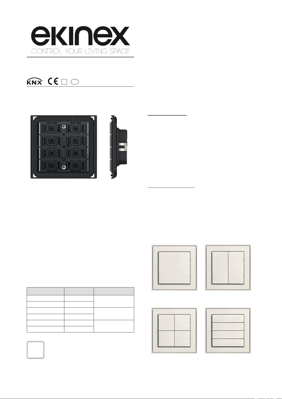
Pushbutton 71 Serie
Code: EK-E12-TP-...
TP1
S
KNX device for switching and control of single loads or
groups of loads and room temperature regulation. It has
to be used in KNX installations for control of homes and
buildings.
Description
The ekinex® pushbutton of 71 Serie is a KNX S-mode device for on/off switching of loads, dimming of lighting devices, controlling of motor drives or other programmable
switching and control functions. The integrated temperature sensor allows the use as a room or zone temperature
controller. It is equipped with an integrated KNX bus communication module and is designed for wall installation
on fl ush-mounting box. Each channel can be freely confi gured to carry out 1 or 2 bus functions and is provided
with programmable LED (blue/green or red/white) e.g.
as a staus feedback or orientation nightlight. Pressing a
rocker, the device sends on the bus a telegram, which
is received and executed by one or more KNX actuators
depending on the confi guration carried out. The device is
powered by the KNX bus line with a SELV voltage 30 Vdc
and does not require auxiliary power.
Datasheet STEKE12TP_EN
Main functional characteristics
• On/off switching of single loads or groups of loads
• Dimming of lighting devices
• Control of motor drives (for roller shutters, blinds, cur-
• Room temperature regulation
• Logic functions
• Sending on the bus of values (temperature, bright-
• Switching to forced functioning (lock)
• Recalling and saving of scenes
• Measuring of room temperature and light brightness
• Diff erent functions programmable for short pressure /
• Status feedback or orientation nightlight through 2-co-
Other characteristics
• Housing in plastic material
• Wall installation in fl ush mounting box
• Protection degree IP20 (according to EN 60529)
REFLEKE12TP
• Classifi cation climatic 3K5 and mechanical 3M2 (accor-
• Pollution degree 2 (according to IEC 60664-1)
• Weight 40 g (70 g with mounting support)
• Dimensions 81 x 77 x 21 mm (WxHxD)
Technical data
• Power supply 30 Vdc from KNX bus line
• Current consumption < 15 mA
• Power from bus < 360 mW
Environmental conditions
• Operating temperature: - 5 ... + 45°C
• Storage temperature: - 25 ... + 55°C
• Transport temperature: - 25 ... + 70°C
• Relative humidity: 95% not condensing
Delivery
The delivery of the pushbutton includes a metallic support
for round fl ush-mounting box, the fi xing screws (2 pairs)
and the KNX terminal block for connection of the bus line.
tains, etc.)
ness, etc.)
through integrated sensors
long pressure of a rocker
lour programmable LEDs
ding to EN 50491-2)
Versions
Device code LED colours Mounting
EK-E12-TP blue / green
EK-E12-TP-RW red / white
EK-E12-TP-BG-NF blue / green
EK-E12-TP-RW-NF red / white
EK-E12-TP-BG-NFW blue / green
EK-E12-TP-RW-NFW red / white
Note. The set of rockers, the plate and the optional
frame for completing the device must be ordered
i
separately. For more information, see also the eki-
®
product catalog or browse www.ekinex.com
nex
with frame of the
form or fl ank series
without frame (‘NF series)
without frame (‘NF series)
with white adapter
Device completed with square
plate, 1-fold Form frame and set of
rockers EK-T1Q-...
Device completed with square
plate, 1-fold Form frame and set of
rockers EK-T4Q-...
1
Device completed with square
plate, 1-fold Form frame and set of
rockers EK-T2R-...
Device completed with square
plate, 1-fold Form frame and set of
rockers EK-T4R-...
Completion of the pushbutton
S
K
The pushbutton is completed through a separate order of:
• a set of rockers that allows the use as a 1-fold, 2-fold
or 4-fold pushbutton;
• a 1-fold plate (square, EK-PQS-...) or a 2-fold plate
(rectangular, EK-P2G-... or EK-P2S-...) in combination
with another bus device of 71 Serie or a 55 x 55 mm
fl ush-mounting insert;
• a square frame of the ekinex
®
form or fl ank series (not
for the ‘NF - No Frame versions).
Rockers
Three-positions rockers with central neutral position have
to be mounted on the pushbutton. Pushing one side of
a rocker (for example the upper one), the pushbutton
sends on the bus a telegram for switching on, increasing
the brightness of luminaires or raising the blinds, while
pushing the other side (for example the lower one), it sends a telegram for switching off , reducing the brightness of
luminaires or lowering the blinds. Each channel is equipped with LEDs which can be freely programmed as status
feedbacks of the loads and as orientation nightlight.
Code set of
rockers *
EK-T1Q-xxx 1 square 60 x 60
Appea-
rance
Nr. and type of
rockers
Modularity
[mm]
Mounting
The device has degree of protection IP20, and is therefore suitable for use in dry interior rooms. The installation
of the device diff ers depending on the mounting with or
without frame (‘NF series).
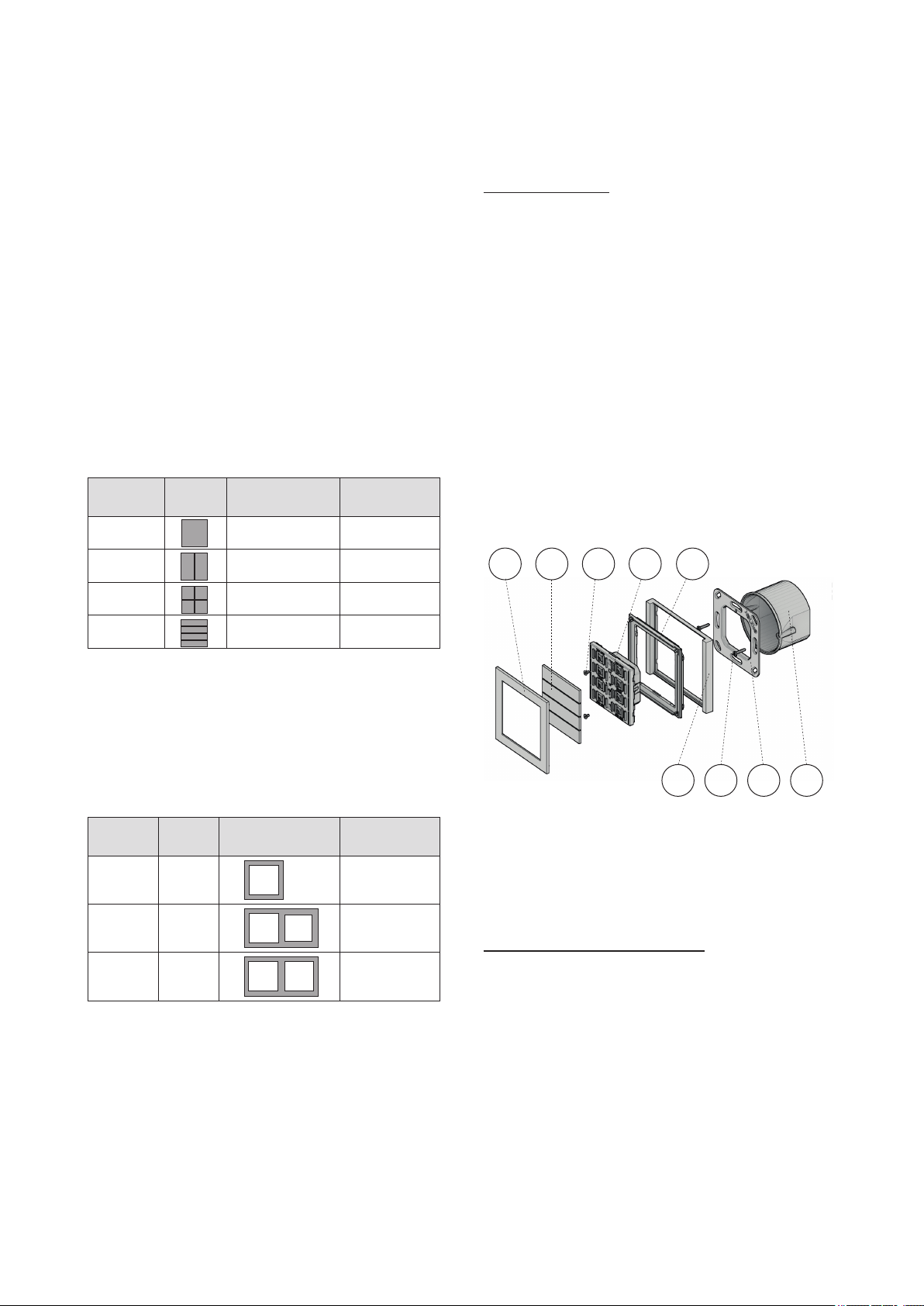
Mounting with frame
Carry out the following steps:
• fi x the metallic support (h) with the pair of screws (g) on
the fl ush-mounting box (i) equipped with fi xing holes at
60 mm distance;
• press for fi xing the pushbutton (d) on the adapter (e);
• insert pushbutton and adapter (d+e) in the metallic support (h). Mounting the device follow also the indication
TOP (arrow tip pointing up) on the rear side of the device;
• snap a square frame (f) of the form or fl ank series, inserting it from the rear of the pushbutton (d);
• enter the bus terminal block, previously connected to
the bus cable in its slot on the rear side (see also: “Connection of the KNX bus line”). At this point it is recommended to carry out the commissioning of the device
(see also “Confi guration and commissioning”) or at least the download of the physical address;
• fasten the device on the metallic support supplied with
the pair of screws (c);
• snap the rockers (b) for the operation of the device;
• snap the plate (a).
EK-T2R-xxx 2 rectangular 30 x 60
EK-T4Q-xxx 4 square 30 x 30
EK-T4R-xxx 4 rectangular 60 x 15
(*) To be completed with the extension for the colour: xxx = MAA (white), xxx = GAG
(silver), xxx = MAL (black)
Plate
The pushbutton may be completed by a square 1-fold plate or by a rectangular 2-fold plate. In both cases the plate
must be necessarily provided with a 60 x 60 mm window
for the mounting of the device.
Plate
code *
EK-PQS-... 1-fold ** 60 x 60
EK-P2G-... 2-fold ***
EK-P2S-... 2-fold *** 60 x 60 (2)
(*) To be completed with the extension for colour, material and fi nishing
(**) For mounting without frame (‘NF) it requires the EK-TAQ adapter
(***) For mounting without frame (‘NF) it requires the EK-A71-... adapter
Type Appearance
Window modula-
rity [mm]
55 x 55 (1)
60 x 60 (1)
Frame
The pushbutton can be completed by a square 1-fold frame or by a rectangular 2-fold frame of the fl ank or form
series. The ‘NF (No Frame) versions of the pushbutton do
not require any frame.
a
Mounting with frame
a) 1-fold plate
b) Rockers
c) Fixing screws (for device)
d) Device (pushbutton 71 Serie)
e) Adapter for mounting with frame (included in the delivery)
f) Frame (square, form or fl ank series)
g) Fixing screws (for metallic support)
h) Metallic mounting support
i) Flush-mounting box
bcde
g
f
h
i
Mounting without frame (‘NF series)
Carry out the following steps:
• insert the metallic support (f) on the adapter (g);
• fi x adapter and support (f+g) with the pair of screws
(e) on the fl ush-mounting box (h) equipped with fi xing
holes at 60 mm distance;
• enter the bus terminal block, previously connected to
the bus cable in its slot on the rear side (see also: “Connection of the KNX bus line”). At this point it is recommended to carry out the commissioning of the device
(see also “Confi guration and commissioning”) or at least the download of the physical address;
• insert the pushbutton (d) on the metallic support (f);
• fasten the device on the metallic support supplied with
the pair of screws (c);
• snap the rockers (b) for the operation of the device;
• snap the plate (a).
E
ESEKE12TPE
2
 Loading...