

Ekinex EK-DB2-TP, EK-DD2-TP, EK-DE2-TP, EK-DC2-TP Applications Manual
Application manual
KNX presence detectors
for ceiling flush mount
EK-DB2-TP, EK-DC2-TP,
EK-DD2-TP, EK-DE2-TP

Application manual
Presence detectors KNX EK-Dx2-TP (x = B, C, D, E)
Release 1.01 - Update: 05/2014 MAEKDx2TP_EN
© SBS S.p.A. – All rights reserved Page 2
Contents
1
Scope of the document .................................................................................................................................. 4
2
Product description ........................................................................................................................................ 5
2.1
Versions ................................................................................................................................................. 5
2.2
Scope of supply ..................................................................................................................................... 6
2.3
Operation ............................................................................................................................................... 6
2.4
Light intensity measurement .................................................................................................................. 6
2.5
Lighting channel ..................................................................................................................................... 6
2.6
HVAC Channel ....................................................................................................................................... 6
2.7
Effective detection range ....................................................................................................................... 7
2.8
Switching, display, sensing and connection elements ........................................................................... 9
3
Configuration ............................................................................................................................................... 10
4
Commissioning ............................................................................................................................................ 10
5
Device settings ............................................................................................................................................ 11
5.1
General ................................................................................................................................................ 11
5.2
Illuminazione - Commutazione ............................................................................................................ 13
5.3
Light – Absolute dimming: Standby lighting ......................................................................................... 15
5.4
HVAC ................................................................................................................................................... 16
5.5
Brightness ............................................................................................................................................ 17
5.6
Brightness value calibration ................................................................................................................. 18
5.7
Parametrization of PIR sensors ........................................................................................................... 19
5.8
Constant light control ........................................................................................................................... 20
6
Functional blocks ......................................................................................................................................... 25
6.1
Lighting control channel ....................................................................................................................... 25
6.1.1
Object 0 Output – Light – Switch................................................................................................ 25
6.1.2
Object 0 Output – Light – Absolute dimming ............................................................................. 25
6.1.3
Object 0 Output – Light – Scene ................................................................................................ 26
6.1.4
Object 1 External switch / status – light – Switch....................................................................... 26
6.1.5
Object 2 External motion – light – Switch .................................................................................. 26
6.1.6
Object 3 Input - Light – Forced control / Disable....................................................................... 26
6.2
HVAC control channel .......................................................................................................................... 27
6.2.1
Object 4 Output – HVAC (switching) – Switch ........................................................................... 27
6.2.2
Object 5 External switch / status – HVAC - Switch .................................................................... 27
6.2.3
Object 6 External motion – HVAC (switching) - Switch ............................................................. 28
6.2.4
Object 7 Input – HVAC – Forced control .................................................................................... 28
6.2.5
Object 7 Input – HVAC – Disable ............................................................................................... 28
6.3
Brightness threshold switch ................................................................................................................. 28
6.3.1
Object 8 Brightness threshold switch value - Switch ................................................................. 28
6.3.2
Object 9 Brightness value - Lux ................................................................................................. 28
6.4
AD Calibration ...................................................................................................................................... 29
6.4.1
Object 10 AD Calibration value .................................................................................................. 29
6.5
Objects for constant brightness control ............................................................................................... 30
6.5.1
Object 16 Constant light control – Switch ON/OFF ................................................................... 30
6.5.2
Object 17 Constant light control – Dim relative .......................................................................... 30

Application manual
Presence detectors KNX EK-Dx2-TP (x = B, C, D, E)
Release 1.01 - Update: 05/2014 MAEKDx2TP_EN
© SBS S.p.A. – All rights reserved Page 3
6.5.3
Object 18 Constant light control – Dim completely .................................................................... 30
6.5.4
Object 20 Constant light control – Forced control ...................................................................... 30
6.5.5
Object 21 Constant light control – Scene ................................................................................... 30
6.5.6
Object 22 Constant light control channel 1 – Output ................................................................. 31
6.5.7
Object 23 Constant light control channel 2 – Output ................................................................. 31
6.5.8
Object 24 Light - standby ........................................................................................................... 31
7
Appendix ...................................................................................................................................................... 32
7.1
KNX Communication Objects summary .............................................................................................. 32
7.2
Warnings .............................................................................................................................................. 33
7.3
Other information ................................................................................................................................. 33
Application manual
Presence detectors KNX EK-Dx2-TP (x = B, C, D, E)
Release 1.01 - Update: 05/2014 MAEKDx2TP_EN
© SBS S.p.A. – All rights reserved Page 4
1 Scope of the document
This manual describes application details for the A1.0 release of the ekinex presence detector series EKDx2-TP (where ‘x’ stands for one of B, C, D, E).
This document is aimed at the system configurator as a description and reference guide for device features
and application programming. For details about mechanical and electrical features, please refer to the
technical datasheet of the device.
This manual and application programs for the device to be used in the ETS® development environment are
available for download on the www.ekinex.com website.
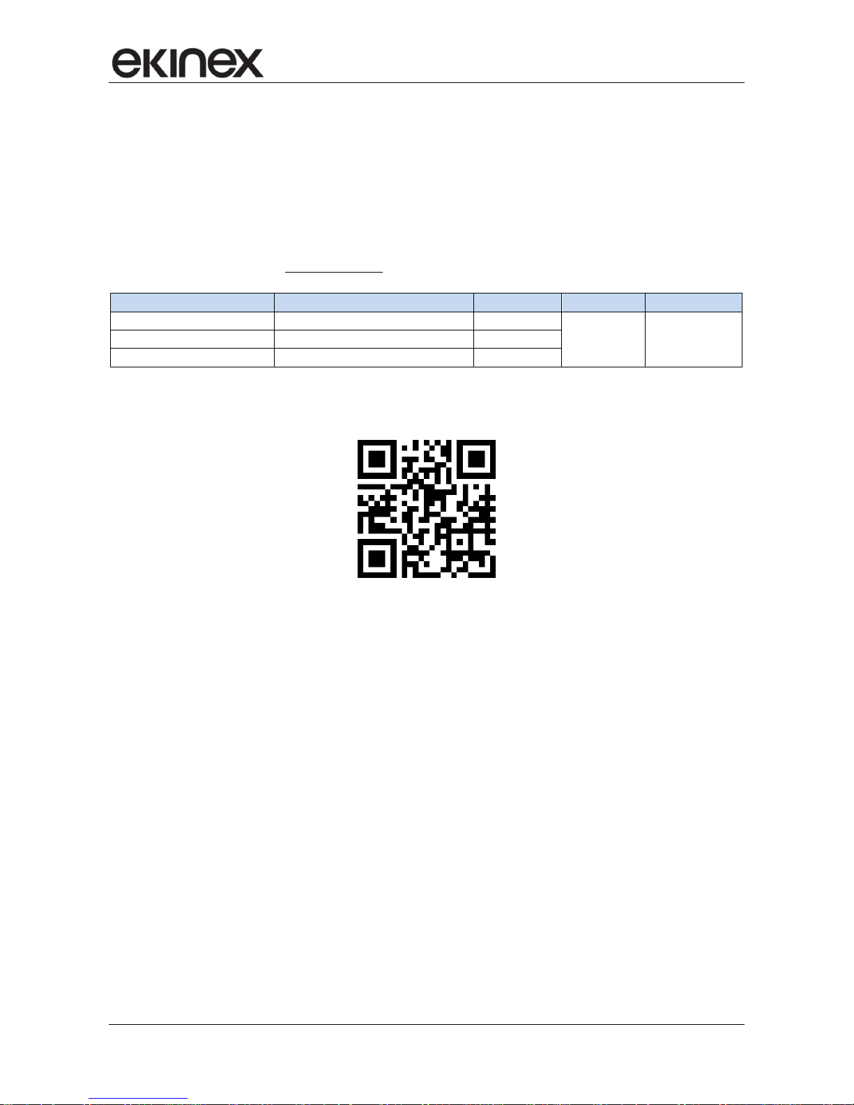
Item File name (## = release) Version Device rel. Update
Technical datasheet
STEKDX2TP_EN.pdf
A1.0 04 / 2014 Application manual
MAEKDX2TP_EN.pdf
-
Application program
APEKSP2TP##.vd4
-
You can access the most up-to-date version of the full documentation for the device using following QR
code:
Application manual
Presence detectors KNX EK-Dx2-TP (x = B, C, D, E)
Release 1.01 - Update: 05/2014 MAEKDx2TP_EN
© SBS S.p.A. – All rights reserved Page 5
2 Product description
The ekinex
®
presence detector is a KNX S-mode device for the indoor detection of occupancy and
movement of people, with an effective detection range of 360° thanks to its three passive infrared (PIR)
sensors.
The detection range can be further extended by employing more ekinex® presence detector devices as slave
units. Two channels C1 and C2 are available for the lighting function; these can be used to achieve a
constant brightness control by using C2 as an offset input respective to C1 (from -50% to +50%).
The light intensity in constant brightness control is measured by the integrated brightness sensor; its value is
made available for bus transmission in Lux units (2 byte). An orientation light function can be programmed
with a standby value (in %) and a duration value (in minutes or hours).
The channel dedicated to HVAC applications allows the independent control of terminal devices dedicated to
Heating, Ventilation and Air-Conditioning.
The device is equipped with an integrated bus communication module and is designed for ceiling flush
mounting. Several versions are available which differ in the detection range and in the lens and frame type.
The device power supply is taken from the KNX bus and no auxiliary power supply is required.
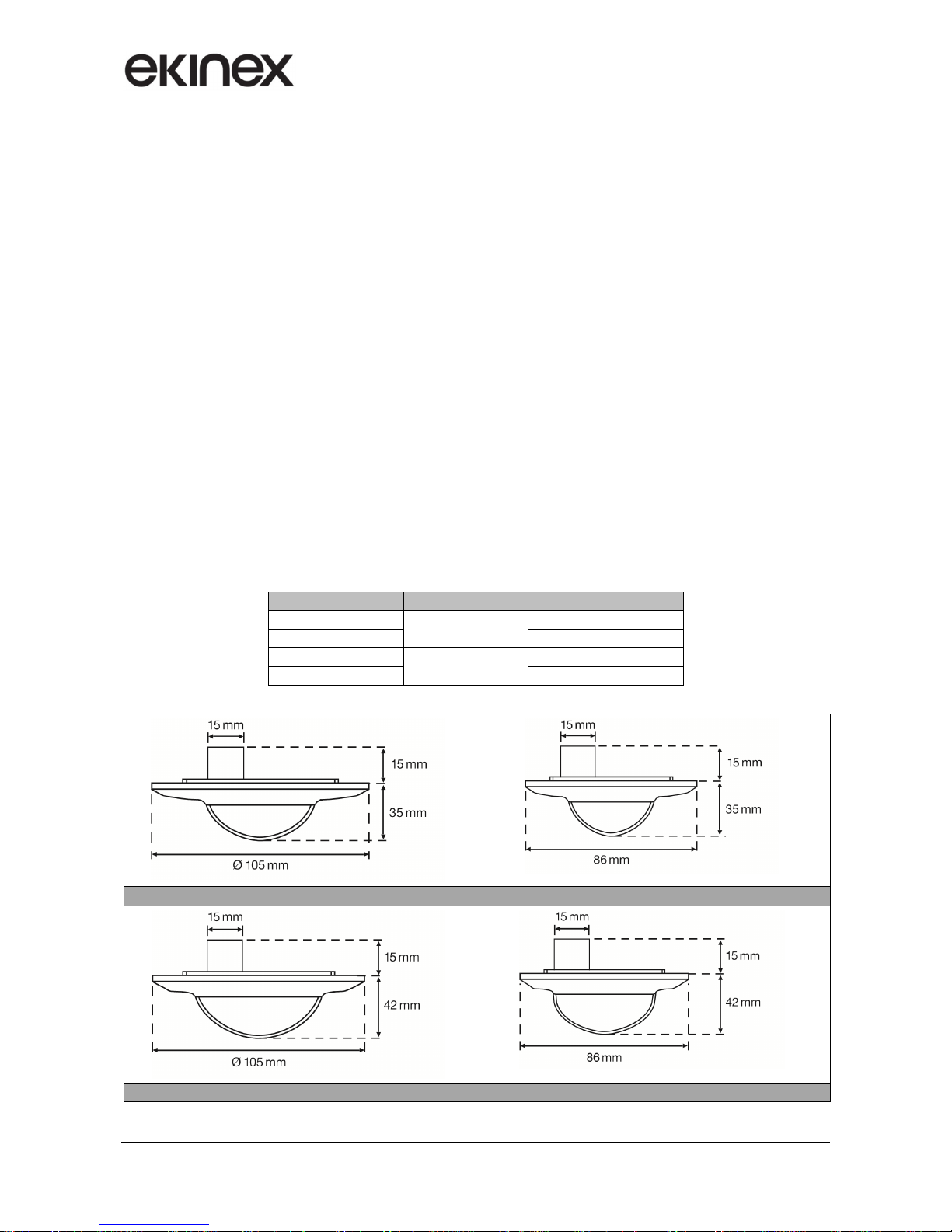
2.1 Versions
The device is available in four versions which differ in the detection range (either 16 or 30 m) and the frame
shape (round or square).
Product code Max range [m] Frame
EK-DB2-TP
16
round Ø 105 mm
EK-DC2-TP
square 86 x 86 mm
EK-DD2-TP
30
round Ø 105 mm
EK-DE2-TP
square 86 x 86 mm
Max range 16 m, round frame Ø 105 mm Max range 16 m, square frame 86 x 86 mm
Max range 30 m, round frame Ø 105 mm Max range 30 m, square frame 86 x 86 mm

Application manual
Presence detectors KNX EK-Dx2-TP (x = B, C, D, E)
Release 1.01 - Update: 05/2014 MAEKDx2TP_EN
© SBS S.p.A. – All rights reserved Page 6
2.2 Scope of supply
The scope of supply of every ekinex® presence detector includes the device, a lens complete with a frame, a
KNX standard plug for the connection with the KNX bus, and a set of fixing screws. No additionally ordered
part is required.
The ETS application program can be downloaded from the ekinex
®
website www.ekinex.com.
In case of need (e.g. for replacement of broken parts), the device and the lens / frame assemblies can be
supplied separately; their codes are listed in the following table.
Order code EAN code Descrizione
EK-SP2-TP 8018417181733
Presence detector (bare device without frame and lens)
EK-CLB 8018417181757
Round frame Ø 105 mm with lens, max range 16 m
EK-CLC 8018417181764
Square frame 86 x 86 mm with lens, max range 16 m
EK-CLD 8018417181771
Round frame Ø 105 mm with lens, max range 30 m
EK-CLE 8018417181788
Square frame 86 x 86 mm with lens, max range 30 m
2.3 Operation
The presence detector reacts to the thermal radiation emitted by moving bodies. A person that crosses the
monitored area automatically activates the lighting. As soon as the sensor does no longer detect any
movement, a delay is started (whose duration is configured through ETS) after which the lighting is switched
off.
If the standby mode is active, the lighting is maintained at a lower brightness level as an orientation light for
the length of the configured standby time.
2.4 Light intensity measurement
The ambient light intensity is measured by an integrated brightness sensor having a linear output profile and
an additional filter matched to the human visual sensitivity.
The light sensor is capable of sending a binary telegram (On or Off) to signal a light intensity level which is
higher or lower than a configured threshold value, regardless to the operation mode. The measured
brightness level in Lux units can further be transmitted on the KNX bus.
2.5 Lighting channel
Two operating modes can be chosen for the lighting channel during the configuration phase:
• fully automatic
• semi-automatic
The fully automatic mode has three different states, i.e. ready, active and passive, whereas the semiautomatic mode only has the ready and active states. In semi-automatic mode, the lighting is not activated
after the detection of a movement, but only after pressing an external pushbutton.
2.6 HVAC Channel
The HVAC channel has the same operating modes and communication objects as the lighting channel; the
detection of movement and presence is enhanced though, introducing the “long duration” principle. The
detection is based on several time windows (from 2 up to 20) of equal width; in every one of these windows
at least one movement must be detected in order to yield a positive response.
Application manual
Presence detectors KNX EK-Dx2-TP (x = B, C, D, E)
Release 1.01 - Update: 05/2014 MAEKDx2TP_EN
© SBS S.p.A. – All rights reserved Page 7
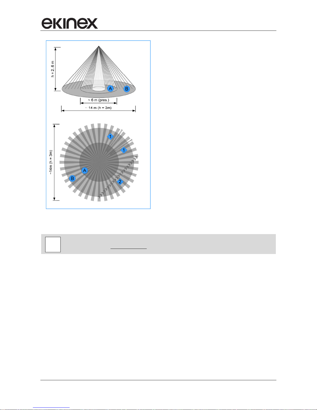
2.7 Effective detection range
The effective sensor detection range varies according to the installation height. The more beaming sectors
are crossed by the person to be detected, the higher is the effectivity at that range.
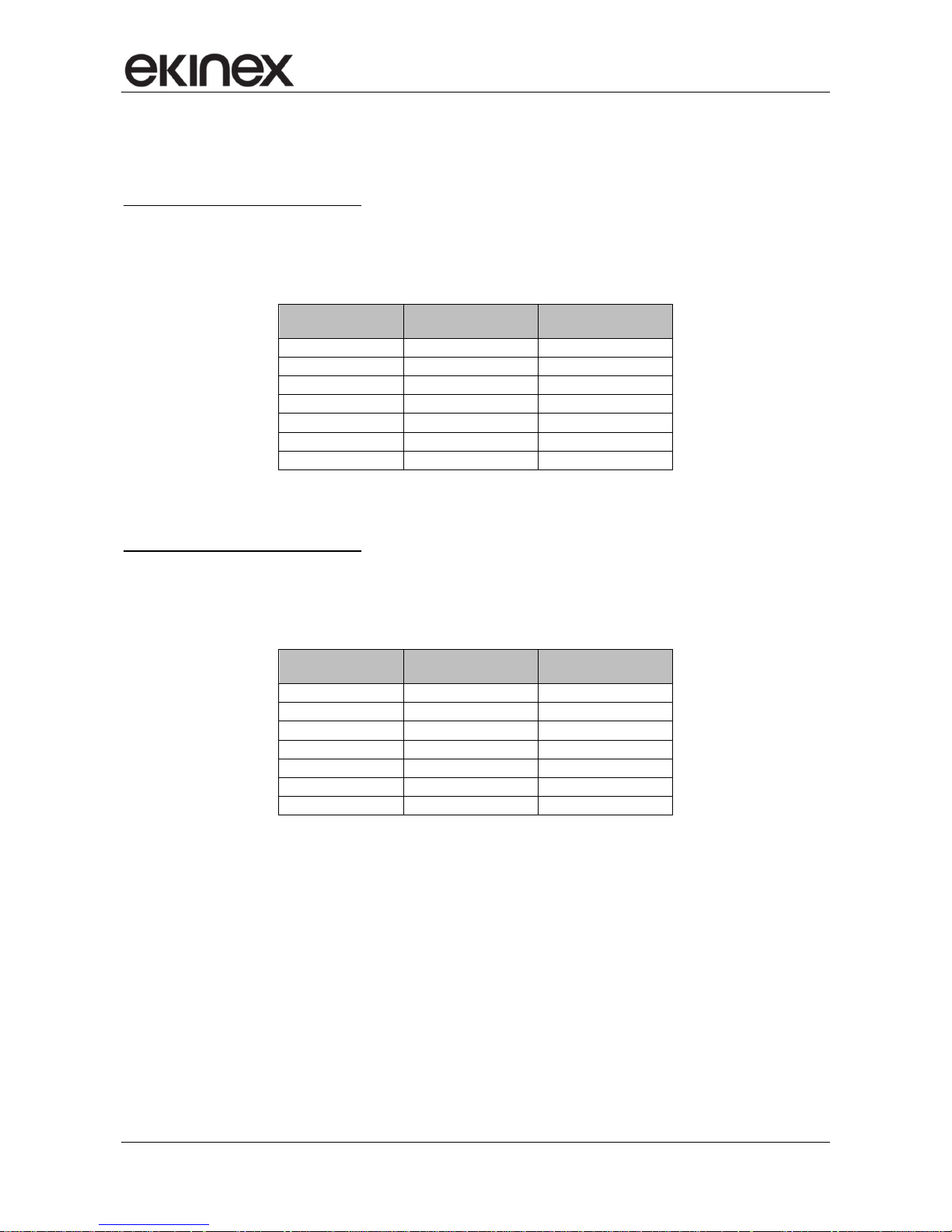
Detectors with 16 m maximum range
The EK-DB2-TP and EK-DC2-TP sensors are capable of detecting presence (people sitting, small
movements) within an area of 4 to 8 meters of diameter, and movement (people crossing the monitoring
field) within an area of 10 to 16 meters of diameter.
Mounting height
[m]
People sitting,
area Ø [m]*
People moving,
area Ø [m]*
2,0 4 10
2,5 5 12
3,0 6 14
3,5 7 16
4,0 8 16
5,0 8 16
6,0 8 16
*) Maximum values
Detectors with 30 m maximum range
The EK-DD2-TP and EK-DE2-TP sensors are capable of detecting presence (people sitting, small
movements) within an area of 5 to 10 meters of diameter, and movement (people crossing the monitoring
field) within an area of 20 to 30 meters ofdiameter.
Mounting height
[m]
People sitting,
area Ø [m]*
People moving,
area Ø [m]*
2 5 20
3 7 26
4 9 28
5 10 30
6 10 30
7 10 30
8 10 30
*) Maximum values
Application manual
Presence detectors KNX EK-Dx2-TP (x = B, C, D, E)
Release 1.01 - Update: 05/2014 MAEKDx2TP_EN
© SBS S.p.A. – All rights reserved Page 8
A. Presence detection zone (working area):
reaction to small movements (e.g. people
sitting, desk activity)
B. Movement detection zone (crossing):
reaction to larger movements (e.g. people
walking)
1. Maximum range:
Crossing several zones
2. Limited range (~ -50%):
Frontal movement within a zone
For further details, please refer to the technical datasheet STEKDX2TP_IT.pdf available on
the ekinex website www.ekinex.com.
i
Application manual
Presence detectors KNX EK-Dx2-TP (x = B, C, D, E)
Release 1.01 - Update: 05/2014 MAEKDx2TP_EN
© SBS S.p.A. – All rights reserved Page 9
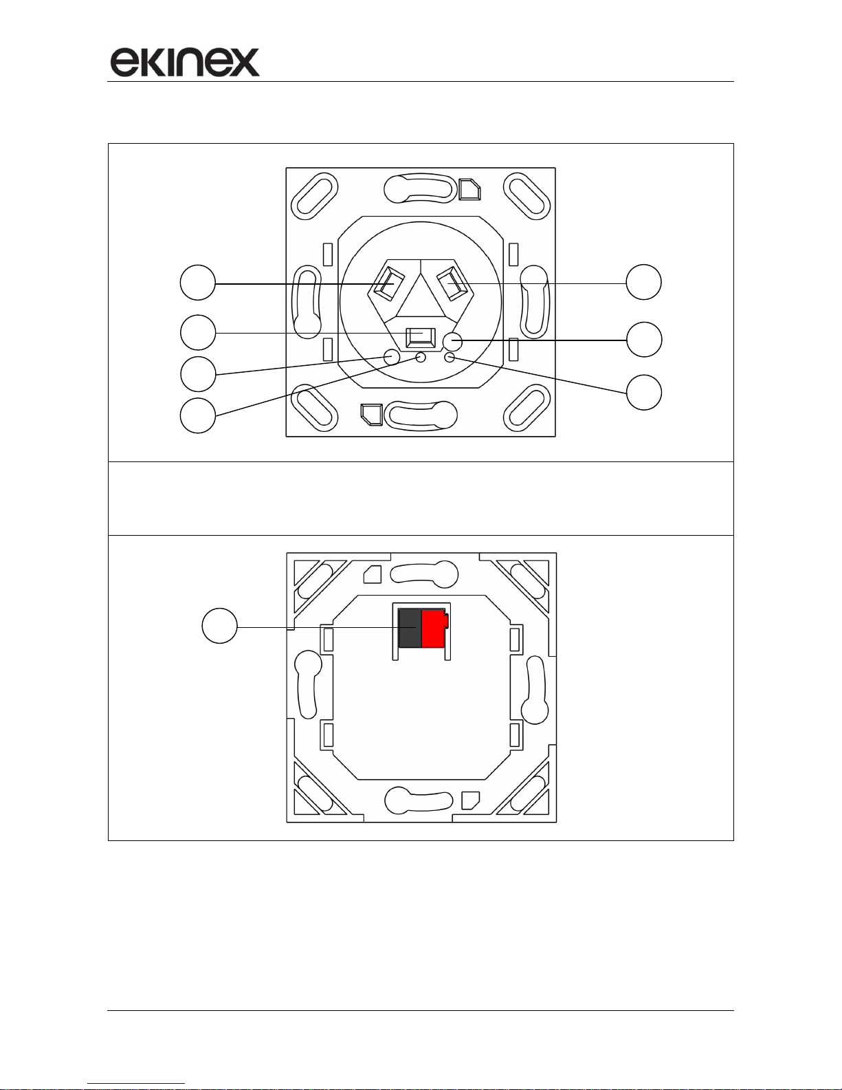
2.8 Switching, display, sensing and connection elements
1) PIR Sensor (nr. 1)
2) PIR Sensor (nr. 2)
3) PIR Sensor (nr. 3)
4) Brightness Sensor
5) Programming LED (red)
6) Signal LED (Green)
7) Programming button
8) KNX bus connection plug
2 3
5
4
1
7
6
8

Application manual
Presence detectors KNX EK-Dx2-TP (x = B, C, D, E)
Release 1.01 - Update: 05/2014 MAEKDx2TP_EN
© SBS S.p.A. – All rights reserved Page 10
3 Configuration
The operation of the device is defined through the software-configured settings.
In order to configure the device, the ETS3 software tool (or later versions) is required, together with the
ekinex® application program APEKSP2TP##.vd4 (## stands for the version number). This latter can be
downloaded from the ekinex website www.ekinex.com.
Please note that the configuration program is exactly the same for all four device types which are subject
of this manual; as a matter of fact, as can also be seen from section 2.2 (Scope of Supply), the code used
in the program name is the code of the “bare” device, and the difference betwees the four device types lies
entirely in the kind of parts assembled on the bare device.
The application program allows the user to access, within the environment of the ETS configuration tool, the
configuration of all of the device’s working parameters. The application program file must be loaded in ETS
(optionally the entire database of all ekinex products can be loaded in one single step); thereafter, any
number of devices of the corresponding types can be added to the current ETS project.
The configurable parameters for the device are described in detail in the following sections.
The configuration can (and usually will) be defined entirely in an off-line fashion, i.e. without being connected
to a device or a KNX network; the transfer of the configuration to the device(s) will therefore happen in a later
phase (the programming phase, described in the following section).
Product code EAN code
ETS application program
(## = revision index)
Communication
objects
(Max nr.)
Group addresses
(Max nr.)
EK-DB2-TP
8018417181023
APEKSP2TP##.vd4
19 254
EK-DC2-TP
8018417181573
EK-DD2-TP
8018417181580
EK-DE2-TP
8018417181597
Configuration and commissioning of KNX devices require specialized skills.
In order to properly acquire such skills, attendance to dedicated courses organized by KNX certified
training centers is recommended.
4 Commissioning
After the device has been configured within the ETS project according to user requirements, the
commissioning of the device requires the following activities:
• electrically connect the device, as described in the product datasheet, to the bus line on the final
network or through a purposely setup network for programming;
• apply power to the bus;
• switch the device operation to programming mode by pressing the programming pushbutton located
on the rear side of the housing. In this mode of operation, the programming LED is turned on steady;
• upload the configuration (including the physical address) to the device with the ETS program.
At the end of the upload, the operation of the device automatically returns to normal mode; in this mode the
programming LED is turned off. Now the device is programmed and ready for use on the bus.
i
i
 Loading...