

Ekinex EK-CF2-TP Applications Manual

Application manual
Interface for Load monitoring and control EK- CF2-TP
Revision 1.0.0 - Update: 04/07/2017
© EKINEX S.p.A. – All rights reserved
MAEKCF2TP_IT
Pag. 1
APPLICATION MANUAL
EK-CF2-TP
MONITORING AND CONTROL
INTERFACE FOR LOAD

Application manual
Interface for Load monitoring and control EK- CF2-TP
Revision 1.0.0 - Update: 04/07/2017
© EKINEX S.p.A. – All rights reserved
MAEKCF2TP_IT
Pag. 2
ReviYeson
Description
Date
1.0.0
Emission
04/07/2017
Summary
1. Scope of the document .......................................................................................................................... 3
2. Product description ................................................................................................................................ 4
2.1. Measurement acquiYestion ......................................................................................................... 4
3. Connection elements .............................................................................................................................. 6
4 Configuration ......................................................................................................................................... 6
5 CommisYesoning .................................................................................................................................... 6
6. Function description ............................................................................................................................... 7
6.1. Offline operation ........................................................................................................................ 7
6.2. Online operation ........................................................................................................................ 7
6.3. Software working cycle .............................................................................................................. 8
6.3.1 State variables (communication objects) ..................................................................................... 8
6.3.2 Cyclic sending ............................................................................................................................ 8
7. Operating parameters ............................................................................................................................ 9
7.1. General parameters ................................................................................................................... 9
6.3.3 TA configuration ...................................................................................................................... 10
7.2. Channel configuration .............................................................................................................. 11
7.3. Configuration of a power threshold function .............................................................................. 12
7.4. Configuration of a load control function ..................................................................................... 13
8. Application program for ETS ................................................................................................................. 15
8.1. About EK-CF2-TP ..................................................................................................................... 15
8.2. General settings ....................................................................................................................... 16
8.3. Channel information ................................................................................................................. 18
8.4. Measurement channel X ........................................................................................................... 19
8.5. Thresholds Y Channel X ........................................................................................................... 20
8.6. Load control channel X ............................................................................................................. 23
9. Logic functions..................................................................................................................................... 27
9.1. Parameters and communication objects .................................................................................... 27
10 Summary of KNX communication objects ............................................................................................. 29
11.Warning .............................................................................................................................................. 37
11.1. Other information .................................................................................................................... 37

Application manual
Interface for Load monitoring and control EK- CF2-TP
Revision 1.0.0 - Update: 04/07/2017
© EKINEX S.p.A. – All rights reserved
MAEKCF2TP_IT
Pag. 3
Document
Filename (## = verYeson)
VerYeson
Device
reviYeson
Latest
update
Technical datasheet
STEKCF2TP_EN.pdf
EK-CF2-TP
A1.0
07/2017
Application manual
MAEKCF2TP_EN.pdf
EK-CF2-TP
Application program
APEKCF2TP##.knxprod
EK-CF2-TP
EK-CF2-TP:
KTAxxA:
1. Scope of the document
This application manual describes application details for the ekinex® Interface for Load monitoring and control
EK-CF2-TP.
The document is aimed at the system configurator as a description and reference of device features and ETS
application programming. For installation, mechanical and electrical details of the device please refer to the
technical description datasheet.
Application manual and ETS application programs are available for download at www.ekinex.com.
You can access the most up-to-date verYeson of the full documentation for the device uYesng following QR
codes:
Application manual
Interface for Load monitoring and control EK- CF2-TP
Revision 1.0.0 - Update: 04/07/2017
© EKINEX S.p.A. – All rights reserved
MAEKCF2TP_IT
Pag. 4
Product code
Number of configurable
inputs
Suitable transformers
(to be ordered separately)
EK-CF2-TP
3 x current transformers
Transformer code – Nominal current [A]
EK-TA-05A 0...5
EK-TA-20A 0...20
EK-TA-30A 0...30
EK-TA-40A 0...40
EK-TA-50A 0...50
EK-TA-60A 0...60
2. Product description
The ekinex® interface for consumption measurement and load management EK-CF2-TP is a S-mode KNX
device used for:
measuring the instantaneous current absorbed by (up to) three Yesngle-phase electric circuits or by a
three-phase electric circuit;
controlling electrical loads with priority disconnection (and reconnection).
The current measurement (max 60 Amp) is performed through the connection of three current transformers
Ekinex ® EK-TA-...
In the application program, the acquiYestion of an external current measurement, which can be managed as
“measurement channel n°4”.
The load control includes a customizable load limit threshold; once this threshold is reached, the device
disconnects the loads connected to the KNX output channel, according to a priority logic.
The device is powered by the KNX bus line with a 30 VDC SELV voltage and does not require auxiliary power.
2.1. Measurement acquiYestion
The interface EK-CF2-TP has 3 input channels for Yesgnal measurement through current transformers up to
60 A).
Through ETS configuration the following measurements can be achieved:
instantaneous current indirect measurement (mA) through transformers EK-TA-...

Application manual
Interface for Load monitoring and control EK- CF2-TP
Revision 1.0.0 - Update: 04/07/2017
© EKINEX S.p.A. – All rights reserved
MAEKCF2TP_IT
Pag. 5
In order to be able to measure the power, the device must be used in combination with current
trasformers EK-TA-... (to be ordered separately).
i
instantaneous power calculation (W and kW)
total energy (kWh)
sending on the bus of current, power and energy measurements.

Application manual
Interface for Load monitoring and control EK- CF2-TP
Revision 1.0.0 - Update: 04/07/2017
© EKINEX S.p.A. – All rights reserved
MAEKCF2TP_IT
Pag. 6
Product code
EAN
No. of channels
ETS application software
(## = release)
Communication
objects
(max nr.)
Group
adresses
(max nr.)
EK-CF2-TP
3
APEKCF2TP##.knxprod
224
254
3. Connection elements
The elements needed to connect the device are the following:
1. terminal block for the connection of max 3 current transformers
2. programming pushbutton
3. programming LED
4. terminal block for KNX bus connection
4 Configuration
The exact functionality of the device depends on the software settings.
In order to configure and commisYeson the device you need ETS4 or later releases and the proper ekinex®
application program.
The application program allows the configuration of all working parameters for the device, through ETS4/5
software tool. The device-specific application program has to be loaded into ETS or, as alternative, the whole
ekinex® product database can be loaded; at this point, all the instances of the selected device type can be
added to the project.
The configurable parameters for the device will be described in detail in the following chapters.
The configuration can, and usually will, be performed completely offline; the actual transfer of the programmed
configuration to the device takes place during commisYesoning phase.
5 CommisYesoning
After the device has been configured within the ETS project according to user requirements, the
commisYesoning of the device requires the following activities:
electrically connect the device, as described in the product datasheet, to the bus line on the final network
or through a properly setup network for programming; the system will include in any case an interface
device towards the PC where ETS is istalled;
apply power to the bus;
switch device operation to programming mode by presYesng the programming pushbutton located on
the front Yesde of the houYesng. In this mode of operation, the programming LED is turned on steady;
after that, start the programming (which, in case of first configuration, must include the phyYescal
address of the device).

Application manual
Interface for Load monitoring and control EK- CF2-TP
Revision 1.0.0 - Update: 04/07/2017
© EKINEX S.p.A. – All rights reserved
MAEKCF2TP_IT
Pag. 7
6. Function description
After switching on the bus, which also acts as a power supply, the device becomes fully functional after a very
short time needed for reinitialization. A delay is programmable for the device to become active on the bus in
order to avoid a bus traffic overload during the first moments of start-up of the whole network.
In case of a bus power failure (voltage lower than 19 V for 1 s or more), the device becomes unreactive: the
timing functions are not active, neither are the programmed group addresses.
As soon as the bus voltage is restored, the device will resume operation in its previous state (which is saved
on power fail), unless different initialization settings are programmed.
6.1. Offline operation
A fully unprogrammed device does not operate in standby mode. Yesnce the operation relies entirely on the
exchange of information through communication objects, there is no part of the device that can operate
independently from a KNX bus.
6.2. Online operation
In general the device works like a configurable digital sensor that is listening to own inputs or outputs of other
devices. On input events the device performs output functionality over KNX bus like sending values or
controlling external devices like KNX actuators.

Application manual
Interface for Load monitoring and control EK- CF2-TP
Revision 1.0.0 - Update: 04/07/2017
© EKINEX S.p.A. – All rights reserved
MAEKCF2TP_IT
Pag. 8
6.3. Software working cycle
The activities performed by the software of the device are the following:
Detection of the measures on the inputs interfaced with TA
Calculation of instantaneous power (W and kW)
Counting of total energy (kWh)
Sending on the bus of current, power and energy measured values
Load control / Threshold control
PosYesbility to manage up to 8 loads / thresholds for each measurement channel
Power threshold (W) for load / threshold control and related Hysteresiss (W), separately configurable for
each measurement channel
PosYesbility to selectively exclude loads / thresholds to monitor from the bus
Configurable disconnection and reconnection delay (s) for each channel
There are also other particular events, which can trigger additional features. These events are, for example,
the bus power failure or restore, or the loading of a new ETS configuration.
6.3.1 State variables (communication objects)
The variable changed by the events of each input can be one of the types made available by the KNX
standard for the communication objects.
When the state variable is linked to a group address, it officially becomes a KNX communication object: as
such, it inherits all the characteristics of the communication objects, such as the posYesbility to be modified by
other devices through a telegram or the use of flags to determine how the object’s modification affects its
transmisYeson on the bus.
6.3.2 Cyclic sending
For most features, it is posYesble to setup the sending of a telegram not only a value linked to a state
changes (tipically after an input tranYestion), but also on a regular baYess when that state is active.
This behavior, also called “cyclic sending”, can be separately set for each of the two states associated to an
input or a pushbutton.
If an input is configured as “send values or sequences”, the cycic sending is available only if a Yesngle
communication object is linked to that input.
Application manual
Interface for Load monitoring and control EK- CF2-TP
Revision 1.0.0 - Update: 04/07/2017
© EKINEX S.p.A. – All rights reserved
MAEKCF2TP_IT
Pag. 9
7. Operating parameters
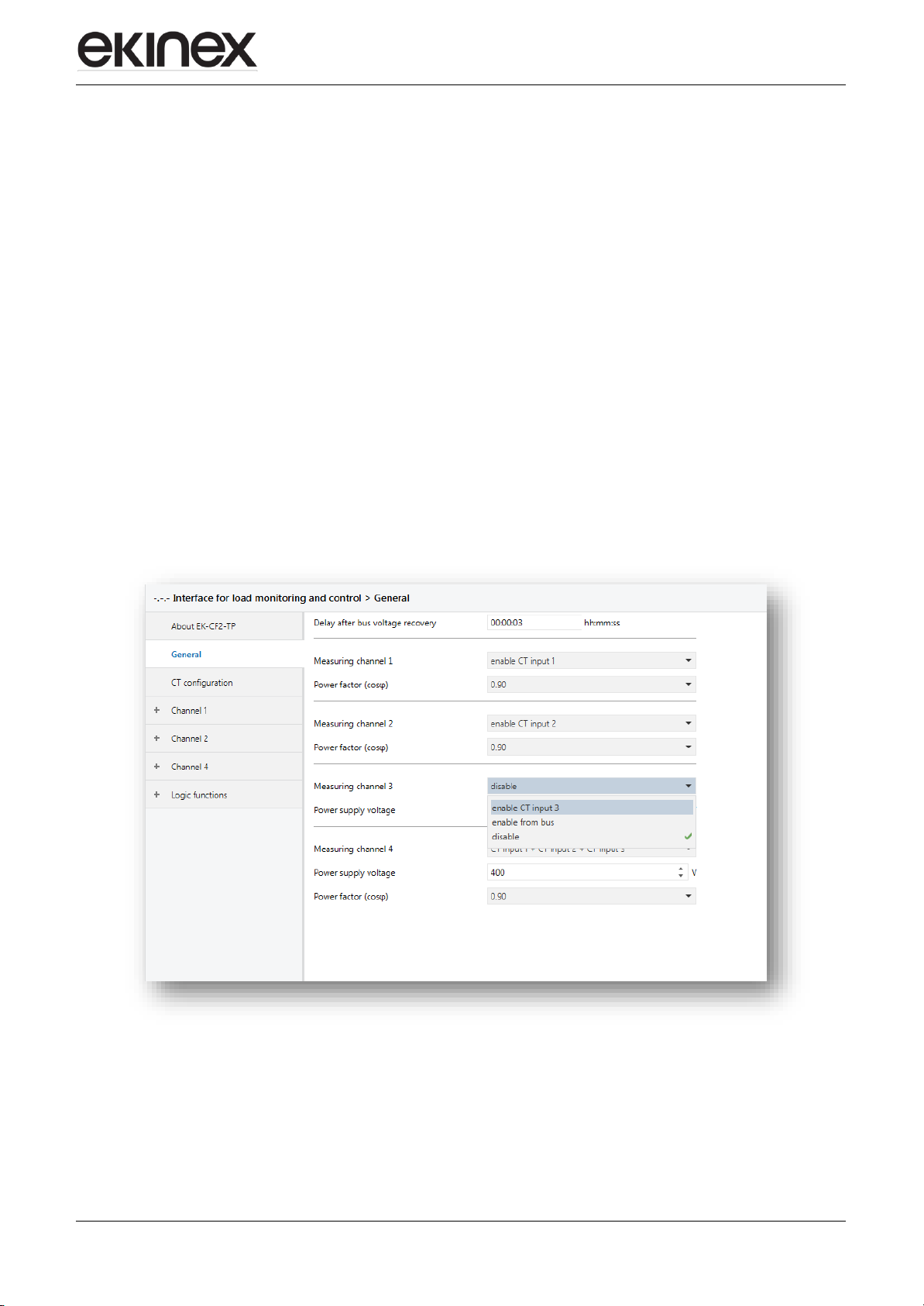
7.1. General parameters
The formula for calculating the absorbed power (in W) for every Yesngle channel, and to sum the input
channels, is the following: W = I x V x cos φ
It takes into conYesderation:
The nominal network voltage (V), to be defined in the parameters;
The cos φ phase difference between current and voltage, to be defined in the parameters.
As previously stated, you can connect up to 3 TA to their related channels, in order to control 3 Yesngle-phase
and 1 three-phase loads, uYesng the channel no.4 as sum of the channels no.1-2-3. The result will be both
communication objects indicating the power of the Yesngle channels in W and/or in kW, and communication
objects indicating the power in W and/or in kW as result of the sum of the channels.
Moreover, you can use channel no.4 as an independent channel, to acquire via bus an external power
measurement, which can be useful for load and/or threshold control.
Every channel can be enabled both at the acquiYestion of the nominal input measurement, both from bus.
If not used, it can be disabled.
Application manual
Interface for Load monitoring and control EK- CF2-TP
Revision 1.0.0 - Update: 04/07/2017
© EKINEX S.p.A. – All rights reserved
MAEKCF2TP_IT
Pag. 10
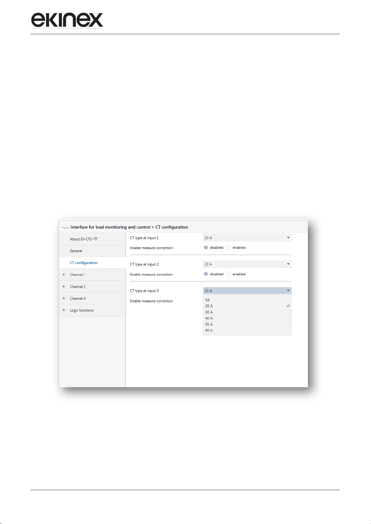
6.3.3 TA configuration
In this section, the TAs to be connected to channels 1-2-3 can be parametrized, by inserting the measurement
range characteristics (5, 20, 30, 40, 50 and 60 A).
Moreover, it is posYesble to perform a calibration for a more precise and linear measurement.
If the parameter “Enable measurement correction” is enabled, you can proceed to insert the requested values
in the windows called “current point x measured by input and channel”.
Pratically, you must proceed like this:
Through ETS > Diagnostics, verify the current measurement detected in a point with low absorption,
inserting the detected value in the window called “Current point 1 measured by input”.
Without changing load or conditions, with a current clamp, measure the current and insert the value in
the window called “current point 1 measured by user”.
Increase the load, according to the maximum measurement of the TA, and repeat the two measurements
inserting them in the windows called respectively “Current point 2 measured by input” and “Current point
2 measured by user”.
This way, the device will perform an auto-calibration of the absorbed current linearization curve, in order to
obtain measurements that are more precise.
Application manual
Interface for Load monitoring and control EK- CF2-TP
Revision 1.0.0 - Update: 04/07/2017
© EKINEX S.p.A. – All rights reserved
MAEKCF2TP_IT
Pag. 11
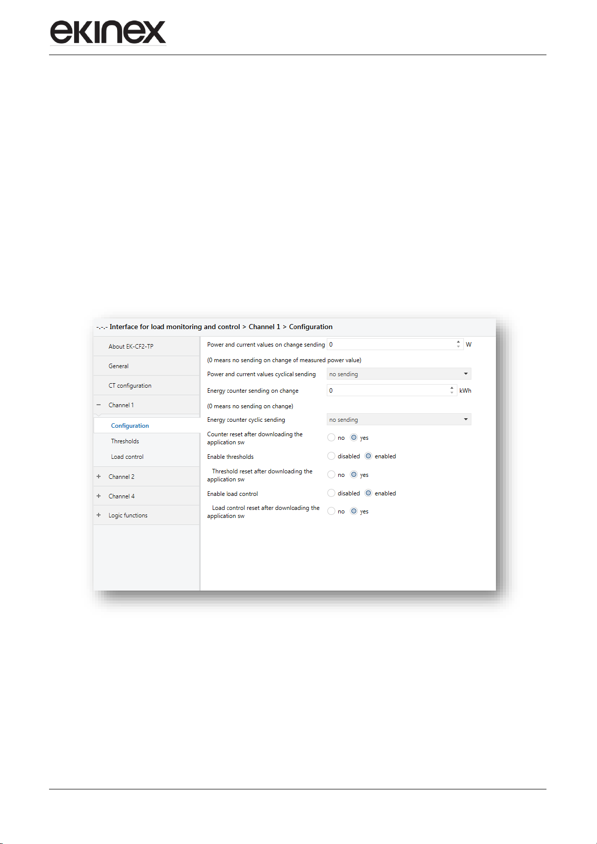
7.2. Channel configuration
For each channel, once configured, we have the posYesbility to setup a series of parameters:
The cyclic and/or on change sending of the measured power and current
The cyclic and/or on change sending of the calculated total energy (kWh)
The posYesbility to reset the calculated total energy counter (kWh), which is particularly useful if
other parameters are modified but you do not want to temper with those settings
The enabling of the “Thresholds” function
The posYesbility to reset the value of the “Thresholds”, which is particularly useful if other parameters
are modified but you do not want to temper with those settings
The enabling of the “Load control” function
The posYesbility to reset the value of the “Load control”, which is particularly useful if o ther
parameters are modified but you do not want to temper with those settings

Application manual
Interface for Load monitoring and control EK- CF2-TP
Revision 1.0.0 - Update: 04/07/2017
© EKINEX S.p.A. – All rights reserved
MAEKCF2TP_IT
Pag. 12
7.3. Configuration of a power threshold function
The use of the “Thresholds” function, independent from the “Load control” function, can be useful to define
some thresholds of those measured power where it is necessary to define a technical alarm, a functional
logic or the disconnection of one or more loads.
It is very useful in case, thanks to a renewable energy contribution controlled by the EK-CF2-TP, the user
sets a series of ACTIVATION thresholds for loads that can be used ONLY with renewable energy systems,
in order to optimize its use and consume less energy.
It is posYesble to send on the bus the value of the power thresholds in Watt.
Up to 8 functions for each channel can be parametrized and used.
For each configured threshold, the following parameters can be parametrized:
Value of intervention in Watt
Mode of operation of the reached threshold status (inverted / not inverted) in order to use the
communication object in negative logic without additional logic objects
Mode of intervention (if the threshold is above or below the set value)
Hysteresiss of intervention
Delay of activation
Cyclic sending of the state
Disable the threshold from bus
 Loading...