

Ekinex EK-BK1-TP Quick Start Manual
Gate
Code:
V1.02 – 11 2015
Main features
REAEKBK1TP
DMX side
• RS485 serial communication port, electrically
isolated from power supply, 120 Ω termination
resistance insertable by a 1-way microswitch
way DMX – KNX TP
EK-BK1-TP
KNX device with gateway function (protocol conversion)
between a serial RS485 network (Master function) with
DMX protocol and a KNX TP network over a twisted
pair communicaton cable.
integration of DMX devices over a RS485 serial network
in a KNX-based automation system for homes and
buildings.
Description
The DMX ekinex® EK-BK1-TP gateway è un
apparecchio KNX modulare per montaggio a quadro. is
a KNX modular unit for panel mounting. It allows you to
exchange informations with one or more slave devices
over a RS485 differential serial network through DMX
protocol. The ekinex gateway acts as DMX master. The
informations exchanged over the DMX network are
updated over the KNX network by means of a twisted
pair (TP) communication cable.
The device manges a one-way data stream: up to 12
bytes of KNX data are defined, each one associated
with a device over the DMX network. The gateway
converts the data coming from KNX master and writes
its value on the corresponding DMX device.
Configuration is performed through a PC application
software which communicates through the integrated
Ethernet port. The application software CGEKBK1TP is
available for download at www.ekinex.com
Data sheet STEKBK1TP_EN
Ideal application in
.
• DMX master communication
• Baud rate: 250 kbaud
• Device addressing from 0 to 512
• 1-byte register writing on max 512 DMX devices
KNX side
• KNX TP (Twisted Pair) communication port set to
9600 baud, electrically isolated from power supply
Ethernet port
• Ethernet communication port (IEEE 802.3), RJ45
connector, minimum cable category: 5E.
Technical data
• Power supply: 8…24 Vac or 12…35 Vdc. Power
Absorption at 24 Vdc: 3,5 VA.
• Installation on 35 mm DIN rail (according to EN
60529)
• Plastic case
• Protection degree IP20 (according to EN 60529)
• Safety class II
• Weight 145 g
• Modular device 4 UM (1 UM = 18 mm)
• Dimensions 72 x 90 x 60 mm (WxHxD)
Environmental conditions
• Operating temperature: - 40 ... + 85°C
• Stock temperature: - 25 ... + 55°C
• Transportation temperature: - 25 ... + 70°C
• Relative humidity: 93% non-condensing
Display and command elements
The device is equipped with a pushbutton and a KNX
programming LED, with a status LED and terminal
blocks for KNX and RS485 network connection. A port
for RJ45 connector for device configuration via Ethernet
as well as two 1-way microswitches are also present.
Pag. 1
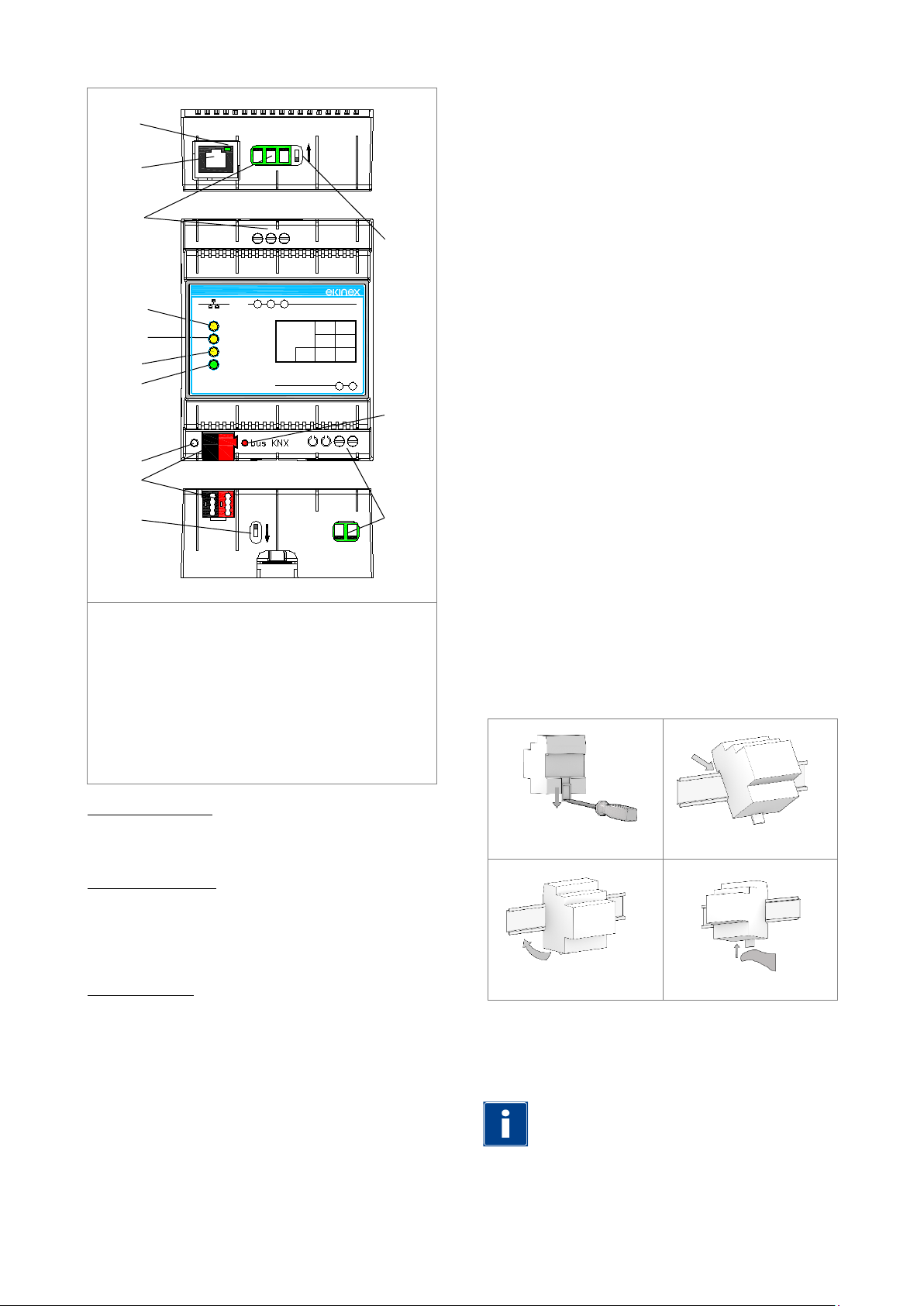
1) KNX bus line terminal blocks
2) KNX programming pushbutton
13) 1-way microswitch B
Note. It is recommended to install the device so to
1
2
5 4 12
6
7 8 9
10
11
13
3
ON
ON
1 2
8...24 Vac
+V 0V
POWER S.
12...35 Vdc
3 4 5
RS485ETHERNET
Dev.
Line
Area
KNX
Device state
DMX
EK-BK1-TP
DMX / KNX TP Converter
Failure
RT-Com RT+
DCEKBK1TP
Inserire codice immagine
3) KNX programming LED
4) Power supply terminal blocks
5) 1-way microswitch A
6) Ethernet port
7) Ethernet port LED
8) Device satus LED
9) DMX communication LED
10) KNX communication LED
11) Device error LED
12) RS485 serial line terminal blocks
• Yellow LED (10) – KNX communication. Normal
mode: blinks when a frame is received. Boot mode:
if fast blinking: no configuration, if very slow blinking
(~0,5 Hz): loading configuration.
• Yellow LED (11) – Device error. Normal mode: ON=
at least one DMX request did not get a correct
answer; OFF=
no error. Boot mode: if fast blinking:
no configuration, if very slow blinking (~0,5 Hz):
loading configuration.
• Green LED (7) – Ethernet port. Normal mode: ON=
Ethernet connector plugged; OFF= Ethernet
connector unplugged. Boot mode: ON=
Ethernet
connector plugged; OFF= Ethernet connector
unplugged.
• Red LED (3) – KNX programming. Normal mode:
physical address programming mode on;
ON=
physical address programming mode off. Boot
OFF=
mode: if fast blinking: no configuration, if very slow
blinking (~0,5 Hz): loading configuration.
Installation
The device has IP20 protection degree and is therefore
suitable for dry indoor environments. The case is
suitable for mouting on a DIN rail (according to EN
60715) inside eletrical distribution cabinets. The proper
installation involves the bus terminal blocks to be in the
lower side.
For installation proceed as follows:
• with the aid of a tool bring the locking device in
completely lowered position (1);
• place the device on the upper edge of the DIN rail
(2);
• rotate the device towards the DIN rail (3);
• push the locking device up untili il stops (4).
Command elements
• Pushbutton that switches between normal mode
and KNX physical address programming.
1-way microswitches
• A - OFF: normal mode active. ON: Boot mode active
• B - OFF: open. ON: RS485 line termination inserted
(120 Ω termination resistance in parallel between
RT+ and RT-)
Display elements
The device can run according to two operating modes:
Normal mode (configuration loaded, Modbus and KNX
communication running) and Boot mode (no
configuration or configuration still loading).
• Green LED (8) – Device status. Normal mode: Slow
blinking (~1 Hz). Boot mode: ON= device on; OFF=
device off.
• Yellow LED (9) – DMX communication. Normal
mode: blinks when a frame is received on the
RS485 port. Boot mode: if fast blinking: no
configuration, if very slow blinking (~0,5 Hz): loading
configuration.
Pag. 2
1
3
2
4
To unmount the device, make sure to unplug the
network connection and the bus terminal from its
housing.
Use a screwdriver to slide down the lock and
remove the device from the rail.
always guarantee full frontal accessibility, in order to
properly display the status LEDs.
 Loading...