

User Guide
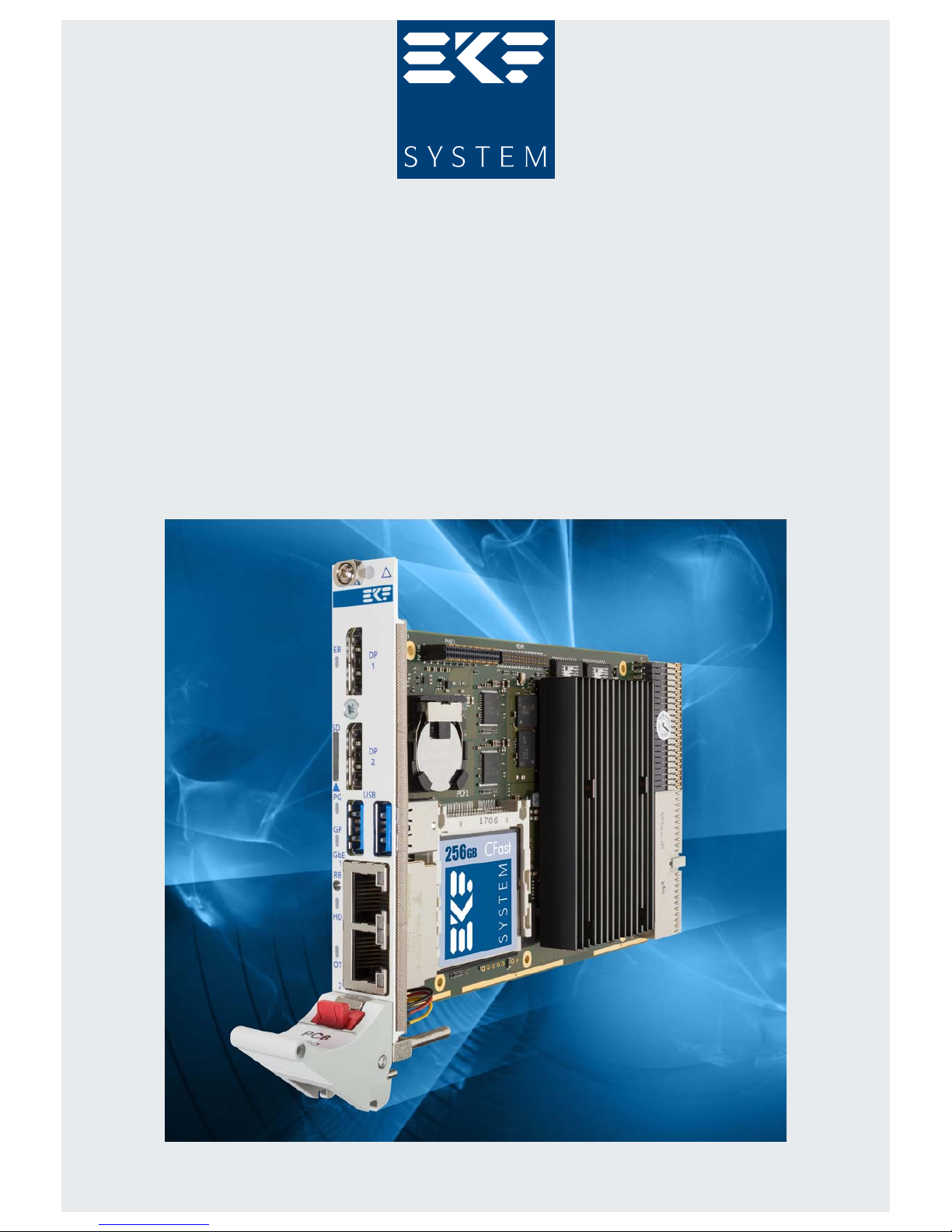
PC6-TANGO • CompactPCI
®
PlusIO CPU Card
Intel
®
Atom™ E3900 Series Processor (Apollo Lake-I SoC)
Document No. 8565 • Edition 4 • 8 December 2017
Preliminary

PC6-TANGO • CompactPCI® PlusIO • Intel® Atom™ E39xx Processor (APL-I SoC)
Contents
About this Manual ........................................................... 5
Edition History......................................................... 5
Related Documents ..................................................... 6
Nomenclature ......................................................... 7
Trade Marks .......................................................... 7
Legal Disclaimer - Liability Exclusion ......................................... 7
Standards ............................................................ 8
Overview............................................................. 9
Technical Features .......................................................... 11
Feature Summary ..................................................... 11
Power Requirements ................................................... 16
Block Diagram........................................................ 17
Top View Component Assembly .......................................... 18
Bottom View Component Assembly........................................ 19
Front Panel Connectors ................................................. 20
Front Panel Switches & Indicators ......................................... 20
On-Board Connectors & Sockets .......................................... 21
Pin Headers .......................................................... 21
Jumpers ............................................................ 21
Microprocessor ....................................................... 22
Thermal Considerations ................................................. 23
Main Memory ........................................................ 24
Graphics Subsystem ................................................... 25
LAN Subsystem ....................................................... 26
Serial ATA Interface (SATA) .............................................. 27
PCI Express® Interface.................................................. 28
Universal Serial Bus (USB) ............................................... 29
Utility Interfaces ...................................................... 30
Real-Time Clock....................................................... 31
SPI Flash ............................................................ 32
CFast™ ............................................................. 33
e•MMC............................................................. 33
Micro SD Card........................................................ 33
Reset............................................................... 34
Watchdog........................................................... 36
Front Panel LEDs ...................................................... 37
PG (Power Good) LED ............................................. 37
GP (General Purpose) LED .......................................... 38
HD (Hard Disk Activity) LED......................................... 38
EB (Ethernet Backplane) LED ........................................ 39
© EKF -2- ekf.com

PC6-TANGO • CompactPCI® PlusIO • Intel® Atom™ E39xx Processor (APL-I SoC)
Hot Swap Detection ................................................... 40
Power Supply Status (PWR_FAIL#)......................................... 40
Mezzanine Side Board Options ........................................... 41
CompactPCI® PlusIO ................................................... 44
Installing and Replacing Components............................................ 48
Before You Begin...................................................... 48
Installing the Board .................................................... 49
Removing the Board ................................................... 50
EMC Recommendations................................................. 51
Replacement of the Battery .............................................. 52
Technical Reference ......................................................... 53
Local PCI Devices ...................................................... 53
Local SMB/I2C Devices .................................................. 54
Board Control and Status Registers (BCSR) ................................... 55
Write/Read Control Register 0 ....................................... 56
Read/Clear Status Register 0 ........................................ 57
Read/Clear Status Register 1 ........................................ 58
Read PLD Revision Register ......................................... 59
GPIO Usage.......................................................... 60
GPIO Usage APL-I SoC ............................................ 60
J-GP UEFI/BIOS Defaults & IEEE 1588 Pulse per Second .................... 62
Manufacturer Mode Jumper (J-MFG) ................................. 63
RTC Reset (J-RTC) ................................................ 64
Connectors .......................................................... 65
Front Panel Connectors ............................................ 66
DisplayPort Connectors ...................................... 67
USB Connectors ............................................ 68
Ethernet Connectors RJ45 .................................... 69
Option M12 X-Coded Ethernet Receptacles ....................... 70
microSD Card Holder ........................................ 72
CFast™ Card Holder .............................................. 73
Mezzanine Connectors ............................................ 76
Expansion Interface P-EXP .................................... 77
High Speed Expansion Connector P-HSE .......................... 78
Pin Headers & Debug ............................................. 80
Front Panel Handle Microswitch Header P-FPH ..................... 80
PLD Programming Header P-PLD ............................... 81
Firmware Programming Header P-SPI ............................ 82
Processor Debug Header P-MIPI ................................ 83
Power Terminal Block ............................................. 84
Backplane Connectors ............................................. 85
© EKF -3- ekf.com

PC6-TANGO • CompactPCI® PlusIO • Intel® Atom™ E39xx Processor (APL-I SoC)
CompactPCI J1............................................. 86
CompactPCI J2 (PlusIO) ...................................... 88
Mechanical Drawing ................................................... 91
© EKF -4- ekf.com
PC6-TANGO • CompactPCI® PlusIO • Intel® Atom™ E39xx Processor (APL-I SoC)
About this Manual
This manual describes the technical aspects of the PC6-TANGO, required for installation and system
integration. It is intended for the experienced user only.
Edition History
Ed. Contents/Changes Author Date
1 User Manual PC6-TANGO, english, preliminary edition (draft)
Text #8565, File: pc6_ug.wpd
jj 18 August 2017
2 Edited “Local PCI Devices” table, “GPIO Usage” table, BCSR registers,
some clean up
gn 2017-09-27
3 Added option M12-X coded front panel GbE connectors jj 20 October 2017
4 Added photos, warning regarding usage in a 64-bit classic environment
also added to table 'Backplane Connector J2' (was already enclosed in
section 'CompactPCI
®
PlusIO')
jjj 8 December 2017
© EKF -5- ekf.com

PC6-TANGO • CompactPCI® PlusIO • Intel® Atom™ E39xx Processor (APL-I SoC)
Related Documents
Related Information
PC6-TANGO Home www.ekf.com/p/pc6/pc6.html
PC6-TANGO User Guide www.ekf.com/p/pc6/pc6_ug.pdf
Related Documents CompactPCI® Serial & CompactPCI® PlusIO
CompactPCI® Serial & PlusIO Overview www.ekf.com/s/smart_solution.pdf
CompactPCI® PlusIO Home www.ekf.com/p/plus.html
CompactPCI® Serial Home www.ekf.com/s/serial.html
Related Documents Mezzanine Modules and Side Cards
C40 ... C48 Series
Mezzanine Storage Modules
www.ekf.com/c/ccpu/c4x_mezz_ovw.pdf
C48-M2 Dual M.2 SATA SSD
Mezzanine Storage Module
www.ekf.com/c/ccpu/c48/c48.html
PCL-CAPELLA Mezzanine Side Card www.ekf.com/p/pcl/pcl.html
PCS-BALLET Mezzanine Side Card www.ekf.com/p/pcs/pcs.html
PR1-RIO Rear I/O Module www.ekf.com/p/pr1/pr1.html
SCS-TRUMPET Mezzanine Side Card www.ekf.com/s/scs/scs.html
Ordering Information
For popular PC6-TANGO SKUs please refer to www.ekf.com/liste/liste_21.html#PC6
For popular Mezzanine Side Cards please refer to www.ekf.com/liste/liste_20.html#C40
© EKF -6- ekf.com

PC6-TANGO • CompactPCI® PlusIO • Intel® Atom™ E39xx Processor (APL-I SoC)
Nomenclature
Signal names used herein with an attached '#' designate active low lines.
Trade Marks
Some terms used herein are property of their respective owners, e.g.
< Atom™, Apollo Lake (APL): ® Intel
< CompactPCI, CompactPCI PlusIO, CompactPCI Serial: ® PICMG
< Windows: ® Microsoft
< EKF, ekf system: ® EKF
EKF does not claim this list to be complete.
Legal Disclaimer - Liability Exclusion
This manual has been edited as carefully as possible. We apologize for any potential mistake.
Information provided herein is designated exclusively to the proficient user (system integrator,
engineer). EKF can accept no responsibility for any damage caused by the use of this manual.
© EKF -7- ekf.com
PC6-TANGO • CompactPCI® PlusIO • Intel® Atom™ E39xx Processor (APL-I SoC)
Standards
Reference Documents
Term Document Origin
CFast™ CFast™ Specification Rev. 1.0 www.compactflash.org
CompactPCI
®
CompactPCI Specification, PICMG® 2.0 R3.0, Oct.
1, 1999
www.picmg.org
CompactPCI
®
PlusIO
CompactPCI PlusIO Specification, PICMG® 2.30
R1.0, November 11, 2009
www.picmg.org
CompactPCI
®
Serial
CompactPCI Serial Specification, PICMG® CPCI-S.0
R2.0, June 12, 2015
www.picmg.org
DisplayPort VESA DisplayPort Standard Version 1.2
December 22, 2009
VESA Mini DisplayPort Connector Standard Ver. 1
October 26, 2009
www.vesa.org
e•MMC Embedded Multi-Media Card Electrical Standard
5.0/5.1
www.jedec.org
Ethernet IEEE Std 802.3, 2000 Edition standards.ieee.org
Precision
Time Protocol
IEEE Std 1588-2008, July 24, 2008 standards.ieee.org
LPC Low Pin Count Interface Specification, Revision 1.1 developer.intel.com/design/
chipsets/industry/lpc.htm
HD Audio High Definition Audio Specification Rev.1.0 www.intel.com/design/chipsets/hdaudio.htm
PCI Express® PCI Express
®
Base Specification 3.0 www.pcisig.com
SATA Serial ATA 3.0 & 3.1 Specification www.sata-io.org
TPM Trusted Platform Module 2.0 www.trustedcomputinggroup.org
TXE Intel
®
Trusted Execution Engine 3.0 www.intel.com
UEFI Unified Extensible Firmware Interface
UEFI Specification Version 2.5
ACPI Specification Version 6.0
www.uefi.org
USB Universal Serial Bus 3.0 Specification, Revision 1.0
November 12, 2008
www.usb.org
© EKF -8- ekf.com
PC6-TANGO • CompactPCI® PlusIO • Intel® Atom™ E39xx Processor (APL-I SoC)
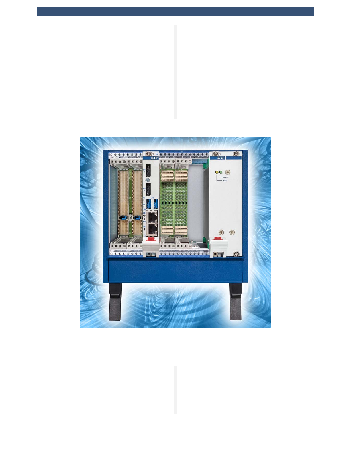
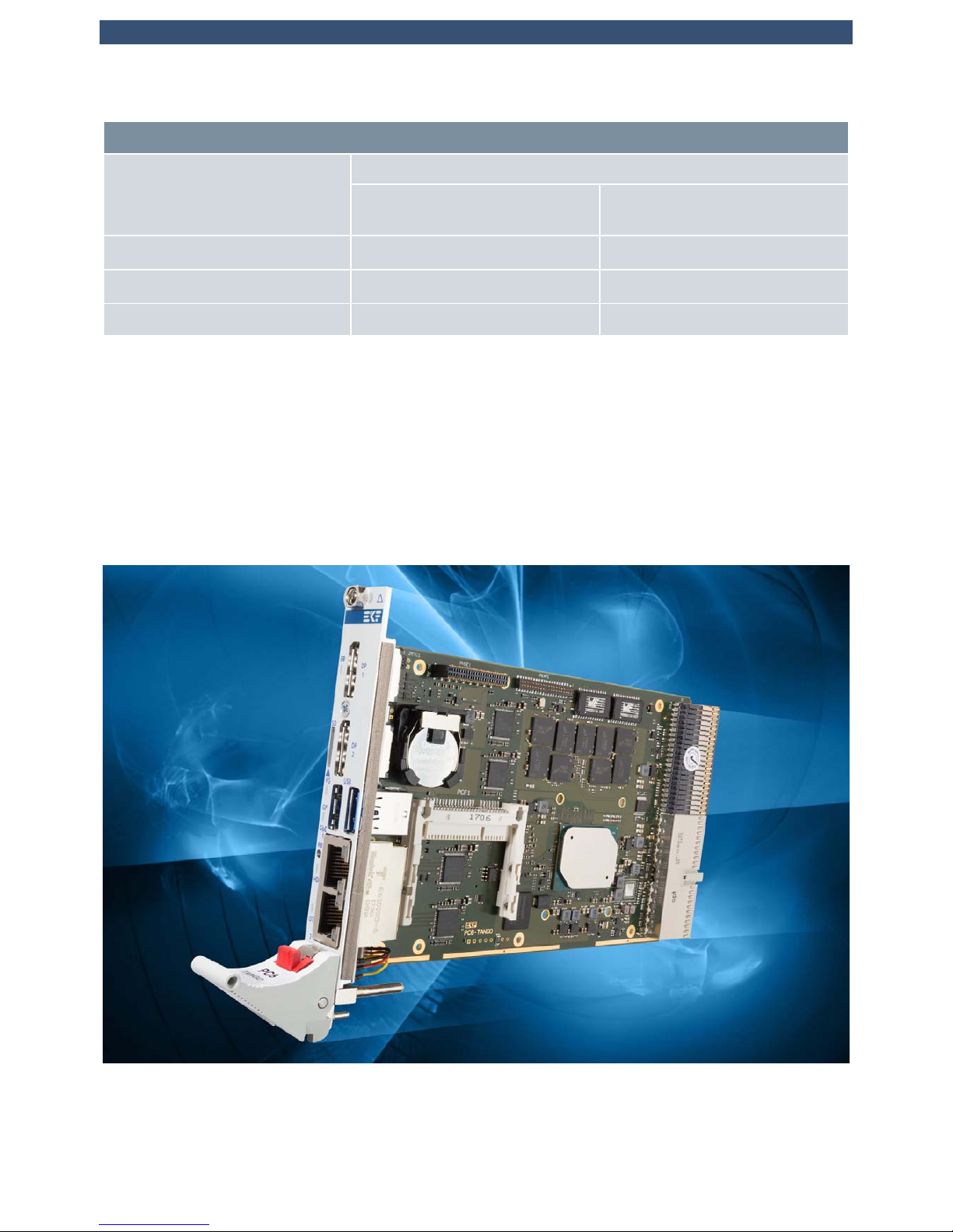
Overview
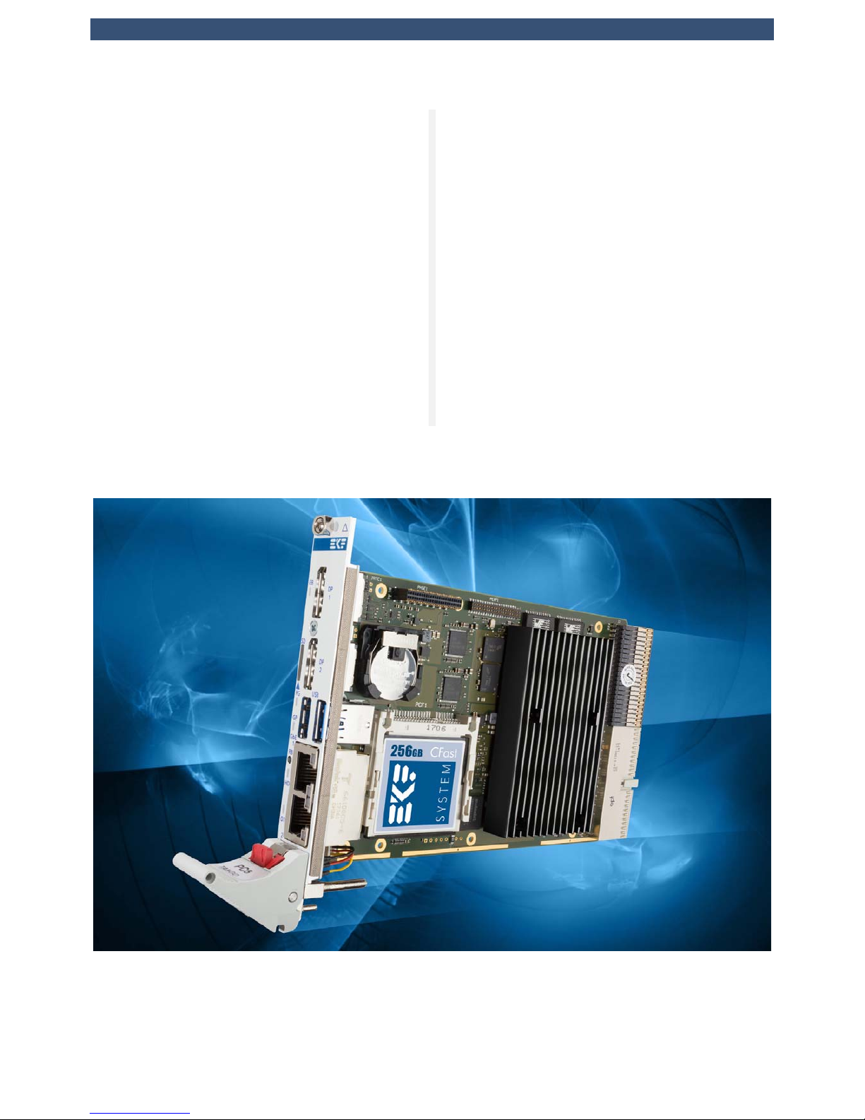
The PC6-TANGO is a low power 4HP/3U
CompactPCI® PlusIO CPU board, equipped with
an Intel® Atom™ E3900-series System-on-Chip
processor (Apollo Lake). The front panel is
provided with two Gigabit Ethernet jacks
(option M12-X), two USB 3.0 receptacles, two
DisplayPort connectors, and a Micro SD Card
slot.
The PC6-TANGO is equipped with 8GB directly
soldered DDR3L ECC RAM, and a CFast™ card
socket as on-board SSD mass storage solution.
Optionally available is an on-board 64GByte
e•MMC flash memory chip. Further more, low
profile SATA SSD mezzanine modules are
available as additional on-board mass storage
solution. The PC6-TANGO backplane connectors
comply with the CompactPCI® PlusIO
specification, suitable for system expansion with
classic CompactPCI® peripheral cards via J1, and
in addition a rear I/O module attached to J2, or
up to four CompactPCI® Serial cards accessed
on a hybrid backplane.
© EKF -9- ekf.com
PC6-TANGO • CompactPCI® PlusIO • Intel® Atom™ E39xx Processor (APL-I SoC)
CompactPCI® PlusIO (PICMG 2.30) is a
standard for rear I/O across J2, specified by the
PICMG®. High speed signal lines (PCI Express®,
SATA, Gigabit Ethernet and USB) are passed
from the PC6-TANGO through the special UHM
connector to the backplane, for usage either on
a PlusIO rear I/O transition module, or
CompactPCI® Serial card slots.
CompactPCI® Serial (PICMG CPCIS.0) defines a
completely new card slot, based on PCI
Express®, SATA, Gigabit Ethernet and USB
serial data lines. On a hybrid backplane, both
card styles can reside, CompactPCI® and
CompactPCI® Serial, with the PC6-TANGO in
the middle as system slot controller for both
backplane segments.
The PC6-TANGO is provided with a set of local
expansion interface connectors, which can be
optionally used to attach a mezzanine side
board, for additional mass storage or front I/O.
The C48-M2 mezzanine module e.g. is
equipped with two M.2 SATA Solid State Drives
(SSD), and fits on the PC6-TANGO while
maintaining the 4HP front panel profile.
© EKF -10- ekf.com

PC6-TANGO • CompactPCI® PlusIO • Intel® Atom™ E39xx Processor (APL-I SoC)
Technical Features
Feature Summary
Feature Summary
General
< CompactPCI® PlusIO (PICMG® CPCI 2.30) System Slot Controller
< Form factor single size Eurocard (board dimensions 100x160mm
2
)
< Mounting height 3U
< Front panel width 4HP (8HP/12HP assembly with optional mezzanine side card)
< Front panel I/O connectors for typical system configuration (2 x USB3, 2 x DisplayPort, 2 x GbE)
< Backplane communication via CompactPCI® J1 and J2 hard metric connectors
< J1 Connector for PICMG® CompactPCI® 32-Bit support
< J2 Connector (UHM high speed) for CompactPCI® PlusIO support (PCIe, SATA, USB, GbE)
< J2 PlusIO configuration allows for either CompactPCI® Serial backplane usage or rear I/O module
attachment
< On-board 2 x SATA 6G mezzanine expansion option for mass storage modules or side cards
< Side cards and low profile mass storage modules available as COTS and also as custom specific
< +5V only board design for low cost system power supply
< PC6-TANGO can deliver +3.3V to CompactPCI® peripheral boards
Processor
< Intel® Apollo Lake-I (APL-I) SoC E39xx Series
< x7-E3950 • 4 Cores • 1.6/2.0GHz • 12W TDP/cTDP • 500/650MHz graphics • 2MB LLC
< x5-E3940 • 4 Cores • 1.6/1.8GHz • 9.5W TDP/cTDP • 400/600MHz graphics • 2MB LLC
< x5-E3930 • 2 Cores • 1.3/1.8GHz • 6.5W TDP/cTDP • 400/550MHz graphics • 2MB LLC
< Graphics Burst, CPU Burst, Intel® Speedstep®
< Intel® Virtualization Technology (Intel® VT-x / VT-d)
< Intel® Trusted Execution Engine (Intel® TXE) 3.0
Firmware
< Phoenix® UEFI (Unified Extensible Firmware Interface) with CSM*
< Fully customizable by EKF
< Secure Boot and Measured Boot supported - meeting all demands as specified by Microsoft®
< Windows®, Linux and other (RT)OS' supported
* CSM (Compatibility Support Module) emulates a legacy BIOS environment, which allows to boot a legacy operating
system such as DOS, 32-bit Windows and some RTOS'
© EKF -11- ekf.com

PC6-TANGO • CompactPCI® PlusIO • Intel® Atom™ E39xx Processor (APL-I SoC)
Feature Summary
Main Memory
< Integrated memory controller up to 8GB DDR3L 1600 +ECC
< Soldered memory for rugged applications
Mass Storage
< On-board CFast™ Card socket (SATA based CompactFlash)
< Front I/O Micro SD Card socket (SDHC, SDXC)
< 128Mbit SPI Flash (UEFI firmware and customer application data)
< Option e•MMC (embedded MMC 5.0 64GByte soldered)
< Option low profile mezzanine card C41-CFAST (secondary CFast™ card socket) via P-HSE connector
< Option low profile mezzanine card C42-SATA (1.8-inch Micro SATA SSD socket) via P-HSE connector
< Option low profile mezzanine card C47-MSATA (dual mSATA SSD module sockets) via P-HSE connector
< Option low profile mezzanine card C48-M2 (dual M.2 SATA SSD module sockets) via P-HSE connector
< Option 8HP assembly side card C44-SATA (2.5-inch SATA SSD/HDD) via P-HSE connector
< Option custom specific mezzanine board design on request
Graphics
< Integrated graphics engine, Gen 9 LP
< DirectX 12.0, OpenCL 2.0 Full Profile, OpenGL 4.3
< HW media acceleration DXVA 2, VAAPI
< HW video decode H264 L5.2, H.265 HEVC, VP9, MVC, MPEG2, JPEG/MJPEG, VC1, WMV9, VP8
< HW video encode H264, SVC, AVC, MVC, MPEG-2
< Content protection PAVP, HDCP 1.4
< 2 x DisplayPort front panel connectors
< DisplayPort™ 1.2a
< Max Resolution 4096 x 2160 @60Hz
Networking
< Up to four networking interface controllers (NIC), 1000BASE-T, 100BASE-TX, 10BASE-T connections
< Intel® I210-IT -40°C to +85°C operating temperature GbE controllers w. integrated PHY
< IPv4/IPv6 checksum offload, 9.5KB Jumbo Frame support, EEE Energy Efficient Ethernet
< IEEE 802.1Qav Audio-Video-Bridging (AVB) enhancements for time-sensivitive streams
< IEEE 1588 and 802.1AS packets hardware-based time stamping for high-precision time synchronization
< Two GbE ports via RJ45 front panel jacks (option 2 x M12-X with mezzanine module P01)
< Option two GbE ports via backplane connector J2 for rear I/O or CompactPCI® Serial backplane usage
© EKF -12- ekf.com

PC6-TANGO • CompactPCI® PlusIO • Intel® Atom™ E39xx Processor (APL-I SoC)
Feature Summary
APL SoC I/O Usage
< 4 x PCIe Gen2 to J2 backplane connector - usage for CompactPCI® Serial peripheral cards or rear I/O module
< 1 x PCIe Gen2 to PCIe switch PI7C9X2G606PR 1:5 lanes (on-board PCIe devices)
< 1 x PCIe to PI7C9X112 PCI bridge (J1 backplane connector, for classic CompactPCI® card support)
< 1 x SATA 6G to on-board CFast™ SSD card socket - can be used as mass storage and boot device
< 1 x SATA 6G to mezzanine expansion connector P-HSE
< e•MMC I/F 400MByte/s (HS400) to embedded MMC 5.0 64GByte (ordering option, mass storage device)
< 2 x USB 3.0 to front panel connectors
< 2 x DisplayPort to front panel connectors
< SDIO (Micro SD Card) front panel slot
< 4 x USB2 to J2 backplane connector
< LPC, Audio, I2C, 2 x USB2 to mezzanine expansion connector P-EXP
< LPC to TPM 2.0 module
On-Board Building Blocks
< Additional on-board controllers, PCIe® based
< PCIe® Gen2 packet switch PI7C9X2G606PR (6-port, 6-lane)
< 2 x Gigabit Ethernet controllers Intel® I210IT (front panel)
< Option 2 x Intel® I210IT (RIO via J2 backplane connector)
< PCIe® to PCI® bridge PI7C9X112 (7 x PCI 33/66MHz)
< Option dual port SATA 6G/3G* controller Marvell® 88SE9170 (to P-HSE mezzanine connector, and J2 RIO)
< Option e•MMC (embedded MMC 5.0 64GByte HS400)
Security
< Trusted Platform Module
< TPM 2.0 for highest level of certified platform protection
< Infineon Optiga™ SLB 9665 cryptographic processor
< Conforming to TCG 2.0 specification
< AES hardware acceleration support (Intel® AES-NI)
Front Panel I/O (4HP)
< 2 x Gigabit Ethernet RJ45 (2 x I210IT)
< 2 x DisplayPort (APL SoC)
< 2 x USB 3.0 Type-A (APL SoC)
< Micro SD Card slot (APL SoC)
© EKF -13- ekf.com

PC6-TANGO • CompactPCI® PlusIO • Intel® Atom™ E39xx Processor (APL-I SoC)
Feature Summary
Front Panel I/O (8HP)
< Option 2 x M12 X-coded receptacles for Gigabit Ethernet (as replacement for RJ45)
CompactPCI® & CompactPCI® PlusIO Backplane Resources
< PICMG® CompactPCI® 2.0 CPU card & system slot controller for J1 based 32-bit CompactPCI® systems
< Support for up to seven CompactPCI® peripheral boards, 33/66MHz (PI7C9X112 PCIe to PCI bridge)
< PICMG® CompactPCI® 2.30 J2 UHM connector according to CompactPCI® PlusIO
< J2 can be used to enable CompactPCI® Serial peripheral card slots for hybrid systems with a split backplane
< J2 can be used alternatively for a rear I/O module e.g. PR1-RIO
< J2 is assigned to 4 x PCIe Gen2 5GT/s (from APL SoC), 1 x SATA 6G/3G* (from Marvell SATA controller), 4 x
USB2 ports (from APL SoC), 2 x Gigabit Ethernet (optional I210IT networking controllers)
* CompactPCI® PlusIO specifies SATA 3G over J2. SATA 6G may be functional but is not guaranteed. The
Marvell SATA RAID controller port available via J2 is therefore configured for 3Gbps by default.
Local Expansion
< Mezzanine side card connectors for optional local expansion
< P-EXP - LPC, Audio, 2 x USB2, I2C, UART Rx/Tx (from APL SoC)
< P-HSE - 2 x SATA 6G (port 1 from APL SoC, port 2 from optional PCIe to SATA controller 88SE9170)
< 4HP Low profile mezzanine module options (to be ordered separately)
< CFast™ Card with C41-CFAST mezzanine module
< SATA 1.8-Inch Solid State Drive with C42-SATA mezzanine module
< Dual mSATA SSD with C47-MSATA mezzanine module
< Dual M.2/NGFF SATA SSD 2230 - 2280 size with C48-M2 mezzanine module
< Custom specific module design
< 8HP Mezzanine side card option (to be ordered separately)
< 2.5-inch SATA SSD/HDD available with C44-SATA
< Side cards available with LPC Super I/O functionality (e.g. to be used for UART RS-232)
< Custom specific side card design
© EKF -14- ekf.com

PC6-TANGO • CompactPCI® PlusIO • Intel® Atom™ E39xx Processor (APL-I SoC)
Feature Summary
Environmental & Regulatory
< Suitable e.g. for industrial, transportation & instrumentation applications
< Designed & manufactured in Germany
< ISO 9001 certified quality management
< Long term availability
< Rugged solution
< Coating, sealing, underfilling on request
< Lifetime application support
< RoHS compliant
< Operating temperature 0°C to +70°C
< Operating temperature -40°C to +85°C (industrial temperature range) on request
< Storage temperature -40°C to +85°C, max. gradient 5°C/min
< Humidity 5% ... 95% RH non condensing
< Altitude -300m ... +3000m
< Shock 15g 0.33ms, 6g 6ms
< Vibration 1g 5-2000Hz
< MTBF tbd years
< EC Regulatory EN55022, EN55024, EN60950-1 (UL60950-1/IEC60950-1)
RT OS Board Support Packages & Driver
< Please refer to external document www.ekf.com/s/rtos_support.pdf
Applications
< General low power industrial computing, for x86 based software
< Rugged systems (e.g. transportation)
< Data concentrator, router, gateway, kiosk systems
< Stand-alone computer (edge computing), mezzanine and rear I/O expansion options
< Small modular systems, CompactPCI® and/or CompactPCI® Serial peripheral card expansion
© EKF -15- ekf.com
PC6-TANGO • CompactPCI® PlusIO • Intel® Atom™ E39xx Processor (APL-I SoC)
Power Requirements
Power Requirements
Board SKU
Load Current [A] at +5V (+0.25V/-0.15V)
Maximum Performance
LFM / HFM / Turbo
1)
Windows 10 Idle
LFM / HFM / Turbo
1)
PC6-tbd
PC6-tbd
PC6-tbd
1)
Intel SpeedStep Frequence Modes LFM: Low Frequency Mode, HFM: High Frequency Mode
© EKF -16- ekf.com
PC6-TANGO • CompactPCI® PlusIO • Intel® Atom™ E39xx Processor (APL-I SoC)
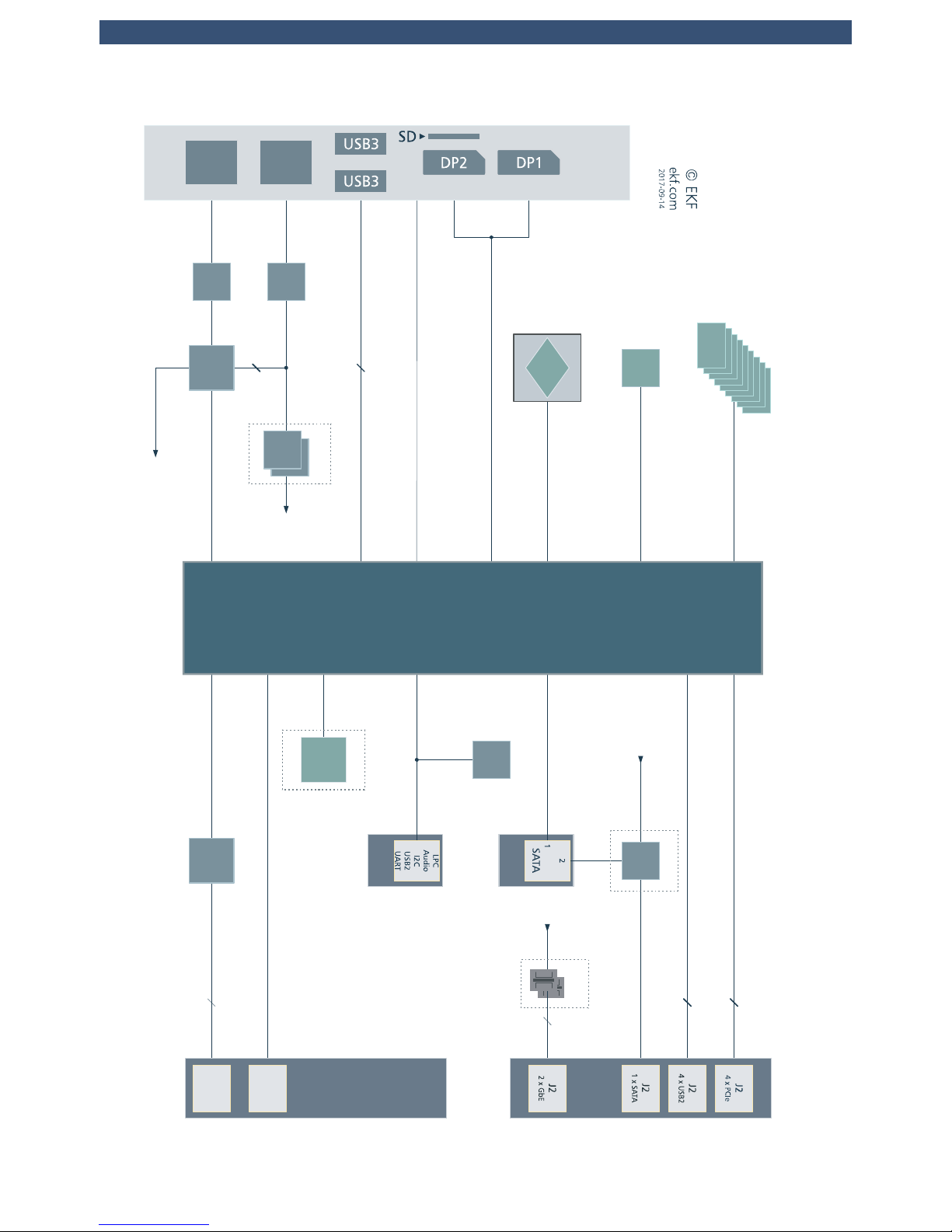
Block Diagram
www.ekf.com/p/pc6/img/pc6_blk.pdf
I210
4
Simplified Block Diagram
PC6-TANGO
CompactPCI PlusIO
®
CPU Card
32bit 33/66MHz
PCIe
Legacy
LPC
PCIe
to PCI
Bridge
PCI x 7
PI7C9X112
Intel® Apollo Lake-I Platform
x7-E3950
(4C
12W)
x5-E3940 (4C 9.5W)
x5-E3930 (2C 6.5W)
Mezzanine
I/O
HSE
EXP
DDR3L Soldered
DDR3L ECC
8GB 1600MT/s
APL-I
Intel®
Atom™
E3900
SoC
HSIO-2
PCIe
P5
eMMC
•
HSIO
8
SATA
P1
HSIO
7-4
PCIe
P0-P3
GbE
DDI0
DDI1
DisplayPort
HSIO
3
PCIe
P4
Flash
TPM
2.0
SPI
SPI
128Mbit
64GB
USB3
2
HSIO 0-1
USB3 P0-P1
PCIe
PCIe
4
3
PI7C9X2G606PR
SATA
SATA
I210
2
DRAM
PCIe
PCIe
Top Mount
Card Holder
CFast
™
SATA
HSIO 9
SATA P0
I210
1
I210
3
PCIe
Switch
1:5
GbE
Mag
Mod
USB2
I210-3
GbE
DDR3L
Option
Option
Option
Option
e
MMC
e MMC
•
4
LPC, I2C0,
HD Audio,
2 x USB2,
UART
9170
SATA
SATA
J2
PCIe
9170
SATA
PCIe
Switch
I210-4
4
x
USB2
SDIO
SD Card
SDHC/SDXC
SD
4x1/1x4
I2C1
I2C
Backplane
CompactPCI
PlusIO
J1
PCI
33/66MHz
Front
Panel
I/O
GbE
2
J2
GbE
1
J1
2
J1
I2C
© EKF -17- ekf.com
PC6-TANGO • CompactPCI® PlusIO • Intel® Atom™ E39xx Processor (APL-I SoC)
HSE
EXP
Intel®
APL
Atom™
PC -6TANGO
PC6-TANGO
EKF
ekf.com•© •
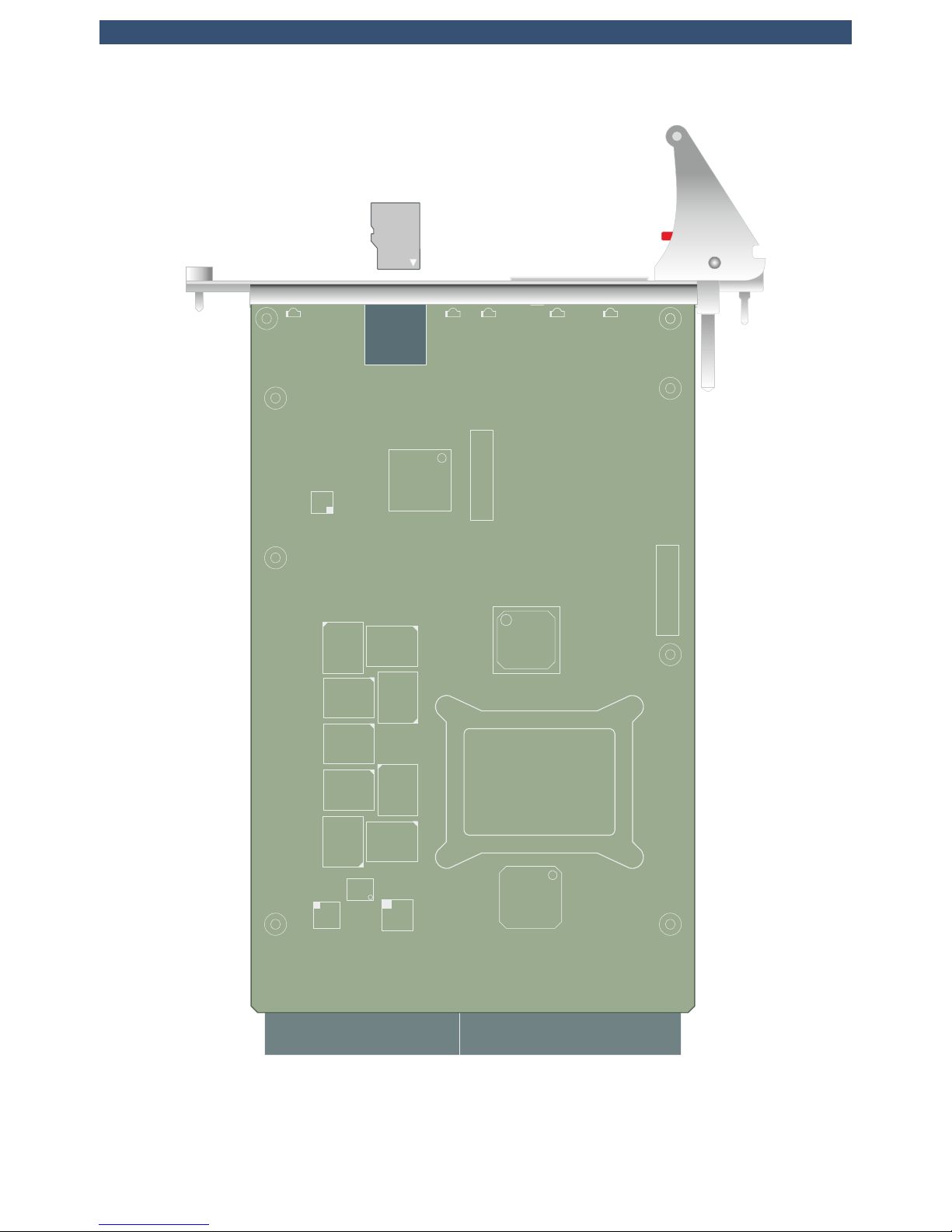
CFast Socket
J1
J2
UHM
J2
UHM
Dual
GbE
P-USB
P-ET H
P-FPH
P-DP1
J-GP
P-DP2
DP1
DP2
2 x
USB
3.0
© EKF
ekf.com
+
J-RTC
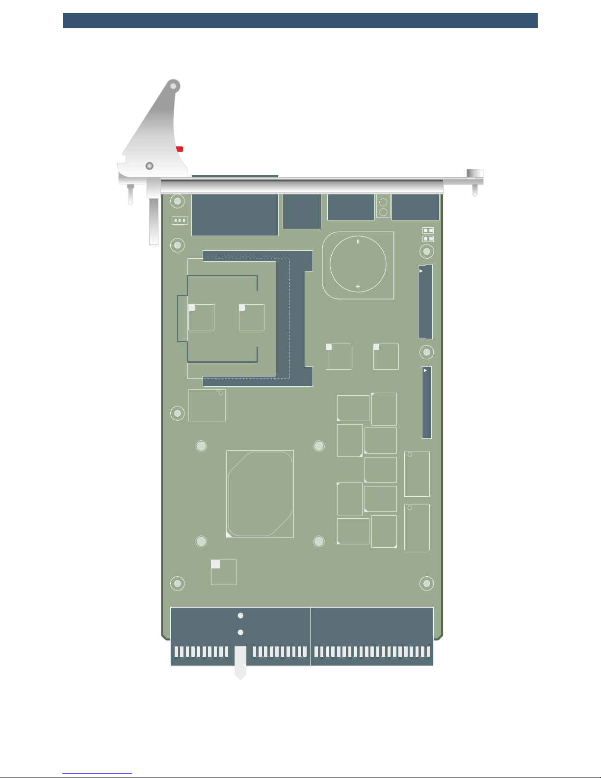
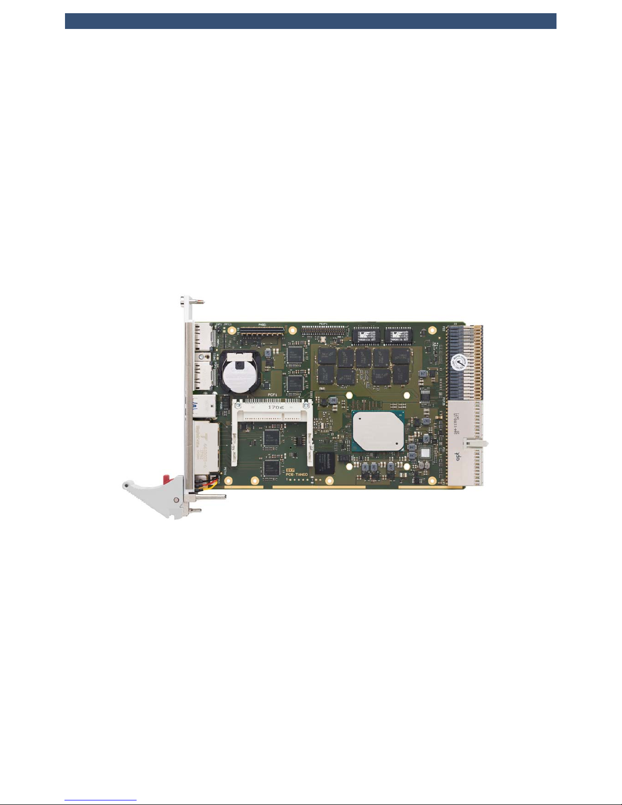
Top View Component Assembly
© EKF -18- ekf.com
PC6-TANGO • CompactPCI® PlusIO • Intel® Atom™ E39xx Processor (APL-I SoC)
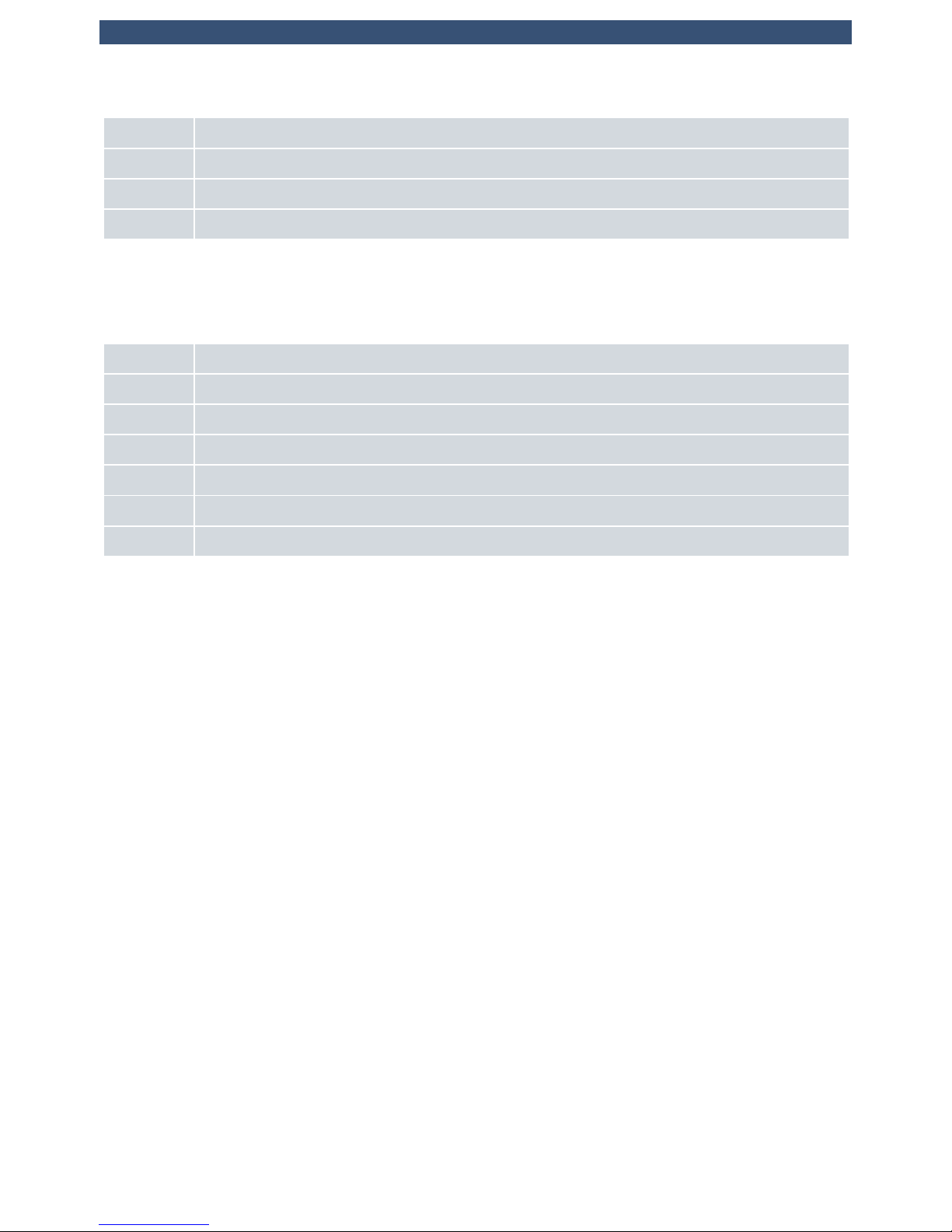
R_BTN
LED
PGD
LED
GP
LED
HD
P-SPI
P-PLD
1
1
LED
GEB
Reset
BTN
Bottom Side
Component
Assembly
LED
HOT
Micro SD
PC6-TANGO EKF ekf.com•© •
Micro
SDHC
SDXC
Bottom View Component Assembly
© EKF -19- ekf.com
PC6-TANGO • CompactPCI® PlusIO • Intel® Atom™ E39xx Processor (APL-I SoC)
Front Panel Connectors
ETH1/2 Dual Gigabit Ethernet RJ-45 receptacles with integrated indicator LEDs (Option M12-X)
DP1/2 DisplayPort digital video output receptacles
USB1/2 Universal Serial Bus 3.0 stacked type A receptacles (USB 3.1 Gen1 5Gbps)
Micro SD Micro SD Card slot push-push type
Front Panel Switches & Indicators
EB LED indicating Backplane Ethernet activity
FPH Front Panel Handle with integrated switch (programmable function, power event button by default)
GP General Purpose bicolour LED
HD Bicoloured LED indicating any activity on SATA ports
HOT LED signalling a CPU over temperature
PG Power Good/Board Healthy bicolour LED
RB System Reset Button (Option)
© EKF -20- ekf.com
PC6-TANGO • CompactPCI® PlusIO • Intel® Atom™ E39xx Processor (APL-I SoC)
On-Board Connectors & Sockets
CFAST Socket for CFast™ Card (6G SATA SSD)
P-EXP Utility EXPansion interface connector (LPC, USB, HD Audio, SMBus), interface to optional side board
P-HSE High Speed Expansion connector 1 x SATA 6G interface to optional low profile mezzanine module or
side board (2 x SATA 6G option)
J1 CompactPCI® Bus 32-bit (universal V(I/O)), 33/66MHz, supports up to 7 peripheral card slots
J2 CompactPCI® PlusIO for rear I/O usage or CompactPCI® Serial peripheral card slots, support for 4 x
PCI Express® Gen2, 4 x USB 2.0, 1 x SATA 6G (option), 2 x GbE (option)
P-MIPI CPU debug port
1)
1)
Connector populated on customers request only
Pin Headers
P-FPH Pin header suitable for front panel handle switch cable harness
P-PLD PLD glue logic device programming connector, not populated
P-SPI SPI Flash device programming connector, not populated
Jumpers
J-GP Jumper to reset UEFI/BIOS setup to EKF factory defaults, IEEE 1588 Pulse per Second output
J-MFG Jumper to enter manufacturing mode, not populated
J-RTC Jumper to reset RTC circuitry (part of SoC), not populated
© EKF -21- ekf.com
PC6-TANGO • CompactPCI® PlusIO • Intel® Atom™ E39xx Processor (APL-I SoC)
Microprocessor
The PC6-TANGO is equipped with an Intel® Atom™ E39xx series processor (code name Apollo Lake-I
aka 'APL-I'). This system-on-chip (SoC) provides integrated graphics, an ECC memory controller and
high speed I/O, resulting in a low power platform design. As of current, Intel® offers three CPU SKU
versions suitable for the PC6-TANGO, differing mainly in the power consumption, caused by
differences in the number of processor cores integrated and internal clock speed.
The processor is housed in a FCBGA-1296 package for direct soldering to the PCB, i.e. the chip cannot
be removed or changed by the user.
Power is applied across the CompactPCI
®
connector J1 (5V). The processors core, graphics and
memory voltages are generated by switched voltage regulators sourced from the 5V plane.
Intel® Atom
TM
Processors Supported
Processor
Number
Physical Cores Core Clock
L/H/B
[GHz]
Cache
[MB]
Gfx Clock
L/H/B
[MHz]
T
CASE
max.
[°C]
TDP/
cTDP
[W]
x7-E3950 4 0.8/1.6/2.0 2 100/500/650 98 12
x5-E3940 4 0.8/1.6/1.8 2 100/400/600 100 9.5
x5-E3930 2 0.8/1.3/1.8 2 100/400/550 103 6.5
L = Lowest Frequency Mode
H = Highest Frequency Mode
B = Boost (Turbo Mode)
Please note: Intel® recommends a GPU clock of 400MHz for industrial applications
T
CASE
is the temperature measured on top of the APL heat spreader (TJ max. = 110°C)
Minimum T
CASE
is -40°C
© EKF -22- ekf.com

PC6-TANGO • CompactPCI® PlusIO • Intel® Atom™ E39xx Processor (APL-I SoC)
Thermal Considerations
The PC6-TANGO is equipped with a passive heatsink. Its height takes into account the 4HP envelope
of a CompactPCI® board. Dependent on the targeted APL-I SoC SKU and ambient temperature, many
applications may not require additional cooling.
However, a reasonable forced vertical airflow through the system enclosure (e.g. bottom mount fan
unit) may be required for demanding applications and for higher ambient temperatures. The
maximum temperature on top of the CPU case must not exceed 100°C e.g. for the E3940.
The APL E3900 AtomTM processors support Intel's Enhanced SpeedStep® technology, enabling
dynamic switching between multiple core voltages and frequencies depending on core temperature
and currently required performance. The processors are able to reduce their core speed and core
voltage in multiple steps down. Additionally a reduction of the graphics core clock and voltage is
possible. This results in a reduction of power consumption and heat dissipation.
Do not try to remove the PC6-TANGO heatsink by yourself, since it is bonded to the CPU by a
Phase-Change-Material (PCM), in order to improve the heat flow between the APL and the heatsink.
© EKF -23- ekf.com
PC6-TANGO • CompactPCI® PlusIO • Intel® Atom™ E39xx Processor (APL-I SoC)
Main Memory
The PC6-TANGO features a total of 8GB DDR3L SDRAM with support of ECC (Error Correction Code).
8GB is the maximum memory size supported by the APL-I SoC. All 18 memory devices are directly
soldered to the board (Memory Down), with a clock frequency of 1600MHz.
You may find external documents which specify a maximum DDR3L speed of 1866MT/s for the APL.
However, this is valid for non ECC designs only.
© EKF -24- ekf.com

PC6-TANGO • CompactPCI® PlusIO • Intel® Atom™ E39xx Processor (APL-I SoC)
Graphics Subsystem
The APL-I SoC is provided with an integrated GPU, running at up to 650MHz clock, based on the 9
th
generation Intel® graphics. For industrial applications and optimum reliability however, Intel®
recommends to operate the GPU at 400MHz fixed clock.
The PC6-TANGO offers two DisplayPort (DP) receptacles in the front panel, for individual use or an
extended desktop application. The VESA DDC standard is supported, allowing to read out important
display parameters, e.g. the maximum supported resolution from the attached monitor. DDC power
+3.3V is delivered via electronic switches to protect the board from an external short-circuit condition
(1.5A) and to prevent back driving current flows.
Graphics drivers for the Intel® GPU are an inherent part of popular operating systems, or can be
downloaded from the Intel® website.
© EKF -25- ekf.com

PC6-TANGO • CompactPCI® PlusIO • Intel® Atom™ E39xx Processor (APL-I SoC)
LAN Subsystem
The Ethernet LAN subsystem is comprised of up to four Gigabit Ethernet ports. Two Intel® i210IT
Gigabit Ethernet controllers are provided to support the front panel RJ45 jacks (backwards compatible
to 10Base-T and 100Base-TX). Another two i210IT NICs are available as an option, for rear I/O usage
via the J2 backplane connector. Each port includes the following features:
< 1000Base-Tx (Gigabit Ethernet), 100Base-TX (Fast Ethernet) and 10Base-T (Classic Ethernet)
capability
< Half- or full-duplex operation
< IEEE 802.3u, 802.3ab Auto-Negotiation for the fastest available connection
< Jumperless configuration (complete software-configurable)
Two bicoloured LEDs integrated into the dedicated RJ-45 connector in the front panel are used to
signal the LAN link, the LAN connection speed and activity status. A further bicoloured LED in front
panel labelled EB displays the state of the optional backplane network ports.
Due to limited internal resources of the APL, each GbE NIC device is connected via its PCI Express®
lane to an on-board PCI Express® 1:5 port packet switch (Diodes PI7C9X2G606PR), thus sharing a
common PCIe Gen2 lane (5Gbps) from the APL-I SoC. With its 5Gbps uplink, the PCIe switch can
smoothly control all four GbE NICs simultaneously at maximum networking speed. However, across
its remaining downstream port the PCIe switch would also feed an optional on-board SATA 6G
controller. For applications which use this hardware configuration intensely, a loss in networking
performance may temporarily occur.
The MAC addresses (unique hardware number assigned to any Ethernet NIC) are stored in dedicated
FLASH/EEPROM components.
The Intel Ethernet software and drivers for the i210IT are available for download from Intel®.
Any of the i210IT controllers supports the IEEE 1588 Precision Time Protocol, important for TSN (Time
Sensitive Networking) applications. In addition, the first NIC (which is connected to the upper RJ45
jack within the front panel) is configured to generate Pulse per Second (PPS) and Pulse per Minute
(PPM) signals for output via the jumper J-GP and to the backplane connector J2. These signals can be
used to trigger events on external hardware such as mezzanine side boards or peripheral cards. The
following routing can be enabled by UEFI/BIOS settings:
< Pulse per Second (PPS): J-GP Pin 1 and CompactPCI® J2 (signal SATA-SCL J2-D14)
< Pulse per Minute (PPM): CompactPCI
®
J2 (signal SATA-SDO J2-D13)
© EKF -26- ekf.com

PC6-TANGO • CompactPCI® PlusIO • Intel® Atom™ E39xx Processor (APL-I SoC)
Serial ATA Interface (SATA)
The PC6-TANGO provides a total of up to four serial ATA (SATA) 6Gbps ports, suitable for attachment
of mass storage devices. Two ports are derived directly from two the APL-I SoC; another two ports are
available as an option via an on-board SATA controller.
The APL SATA port P0 is in use for an on-board CFast™ connector. CFast™ cards are available up to
512GB storage capacity as of current, sufficient for typical operating system installation and
application programs.
The APL SATA port P1 is wired to the mezzanine connector HSE, for optional usage with a low profile
mezzanine module such as the C48-M2 (M.2 SATA SSD storage).
As an option, the PC6-TANGO can be equipped with a discrete on-board SATA controller in addition,
providing another two SATA 6Gbps ports. The Marvell 88SE9170 is an SATA 6Gbps I/O controller,
connected to the system via PCI Express®. One of the 88SE9170 SATA ports is wired to the
mezzanine connector HSE, and the other to the backplane connector J2. The 88SE9170 shares a
common PCIe lane from the APL SoC with the on-board NIC devices, by means of a PCI Express®
packet switch. Therefore the maximum throughput of the 88SE9170 SATA ports may be somewhat
reduced compared to the APL native SATA ports.
As mentioned, a single SATA port is used to supply the CompactPCI® PlusIO SATA interface on the
backplane or rear I/O module, via the J2 UHM connector. Please note, that the CompactPCI® PlusIO
specification refers to SATA data rates of 1.5Gbps and 3Gbps. EKF has tested successfully also 6G over
the backplane with sample devices, but cannot guarantee this data rate under any condition. Other
devices and other backplane brands/types in use may cause a different result. If in doubt, the Marvell
SATA controller should be initialized for 3Gbps. EKF recommends that customers validate their
particular SATA 6G application thoroughly, since SATA channel data errors can decrease the
performance considerably.
A bicolor LED named HD located in the front panel, signals the activity status of any APL SATA device
(green) or 88SE9170 SATA device (yellow).
Windows® drivers and software for the 88SE9170 is provided by Marvell and can be downloaded
from the EKF website.
© EKF -27- ekf.com

PC6-TANGO • CompactPCI® PlusIO • Intel® Atom™ E39xx Processor (APL-I SoC)
PCI Express® Interface
The PC6-TANGO is provided with four PCI Express® (PCIe) Gen 2 lanes for rear I/O expansion, derived
from the APL-I SoC (PCIe P0-P3), and available via the backplane connector J2. By software strapping,
these lanes can be configured as 4 PCIe links x1, or one link x4, for use on a hybrid backplane with
CompactPCI® Serial peripheral slots, or on a rear I/O module.
Another two PCI Express® lanes from the APL-I SoC are in use on-board.
The APL PCIe lane P4 is used as upstream port for an 1:5 PCIe packet switch, which controls all four
i210IT GbE controllers, and in addition an optional SATA controller.
The APL PCIe lane P5 is connected to the PCIe to PCI bridge, which allows to control up to eight
CompactPCI® Classic peripheral slots across the backplane connector J1.
© EKF -28- ekf.com

PC6-TANGO • CompactPCI® PlusIO • Intel® Atom™ E39xx Processor (APL-I SoC)
Universal Serial Bus (USB)
The APL-I SoC on the PC6-TANGO is configured to support two USB 3.1 Gen1 Type-A front panel
connectors (USB 3.1 was formerly known as USB 3.0 5Gbps SuperSpeed). Both front panel USB
receptacles can source a minimum of 1.5A/5V each, over-current protected by electronic switches.
Another four USB 2.0 ports are available across the backplane connector J2, for rear I/O usage, or on
a CompactPCI Serial peripheral card slot. In addition, two more USB 2.0 ports are wired to the legacy
mezzanine connector P-EXP, for optional usage on side cards.
© EKF -29- ekf.com

PC6-TANGO • CompactPCI® PlusIO • Intel® Atom™ E39xx Processor (APL-I SoC)
Utility Interfaces
Besides the high speed mezzanine interface connector P-HSE, the PC6-TANGO is provided with the
utility interface expansion connector P-EXP, which comprises several legacy interfaces, which may be
useful for system expansion on mezzanine cards:
< HD Audio
< LPC (Low Pin Count) @ 25MHz clock
< I2C
< 2 x USB 2.0
< UART Rx/Tx
All signals are controlled by the APL-I SoC. The I2C signals on P-EXP are derived from the APL I2C port
0 and not shared with any other components on the PC6-TANGO, thus avoiding any potential I
2
C
address conflict.
The HD Audio port requires an additional audio codec, as provided e.g. on the PCS-BALLET side card.
The LPC bus presents an easy way to add legacy interfaces to the system. EKF offers a variety of
mezzanine expansion boards (side cards), to be attached on top of the PC6-TANGO, featuring all
classic Super-I/O functionality, for example the PCS-BALLET. Access to the side card connectors PS/2
(mouse, keyboard), COM, USB and audio in/out is given directly from the common 8HP front panel.
The LPC I/F is shared with the TPM (Trusted Platform Module) on the PC6-TANGO. Some side cards
however may be also equipped with a TPM device, which would result in a conflict. For usage
together with the PC6-TANGO, side cards must be ordered w/o a TPM soldered.
The USB 2.0 ports can be used on a mezzanine side card for front I/O, or for on-board devices.
A lean UART I/F is also available via the P-EXP connector, comprised of Rx and Tx (TTL level signals)
only. It can be used for processor debug, or customer application. External transceivers to RS-232 or
RS-485 would have to be added, and in-band data flow control (XON/XOFF) should be setup.
© EKF -30- ekf.com

PC6-TANGO • CompactPCI® PlusIO • Intel® Atom™ E39xx Processor (APL-I SoC)
Real-Time Clock
The PC6-TANGO is provided with a time-of-day clock and 100-year calendar, integrated into the APL-I
SoC. A battery on the board supplies the clock circuitry whenever the computer main power is turned
off. The PC6-TANGO uses a holder to retain a BR2032 lithium coin cell, giving an autonomy of more
than 5 years.
Alternately a leaded BR2032 battery can be soldered directly to the board for increased ruggedness,
or if the PC6-TANGO PCB shall be coated.
In applications were the use of a battery is not permitted, a SuperCap can be soldered instead of the
battery.
© EKF -31- ekf.com

PC6-TANGO • CompactPCI® PlusIO • Intel® Atom™ E39xx Processor (APL-I SoC)
SPI Flash
The UEFI/BIOS firmware is stored in a flash device, attached via the Serial Peripheral Interface (SPI). Up
to 16MByte of code, firmware and user data may be stored nonvolatile here.
The SPI Flash contents can be updated by a DOS or Linux based tool. This program and the latest
PC6-TANGO UEFI/BIOS binary are available from the EKF website. Read carefully the enclosed
instructions. If the programming procedure fails e.g. caused by a power interruption, the PC6-TANGO
may no more be operable. In this case you would have to send in the board, because the Flash device
is directly soldered to the PCB and cannot be changed by the user.
© EKF -32- ekf.com

PC6-TANGO • CompactPCI® PlusIO • Intel® Atom™ E39xx Processor (APL-I SoC)
CFast™
The PC6-TANGO is provided with a CFast™ host connector, for user replaceable mass storage. It is
suitable for CFast™ 2.0 cards, which have the same dimensions as CompactFlash™ cards, but are
operated in SATA mode. Industrial CFast™ SSD cards are available up to 256GByte as of current. The
SATA channel available on the CFast™ socket is derived directly from the APL-I SoC. A CFast™ card can
be used as boot device (i.e. OS installation) in most applications.
e•MMC
The PC6-TANGO can be equipped with an Embedded Multi-Media Card (e•MMC) as an option. This
is a fast Flash based storage solution which has been proved in mobile devices. The chip is soldered
directly to the board, with a capacity of 64GByte as of current. The interface is specified by a Jedec
standard, and is directly controlled from the APL-I SoC. The e•MMC may be useful for permanent
data storage and small OS installation, since its 8-bit data bus is operated in a high speed mode
(HS400) for sequential read up to 250MBps.
Micro SD Card
For removable data storage, the PC6-TANGO provides a Micro SD Card socket, accessible through the
front panel. Industrial Micro SDHC cards are available up to 32GByte, sufficient for permanent data
storage at reasonable transfer speed in many applications. The Micro SD Card socket is controlled
immediately by the APL-I SoC (SDIO I/F).
© EKF -33- ekf.com

PC6-TANGO • CompactPCI® PlusIO • Intel® Atom™ E39xx Processor (APL-I SoC)
Reset
The PC6-TANGO is provided with a supervisor circuit to monitor supply rails like the CPU core voltage,
DDR3L supply voltage 1.35V, 1.05V, 3.3V or 5V.
To force a manual board reset, the PC6-TANGO offers a small tactile switch within the front panel.
This push-button is indent mounted and requires a tool, e.g. a pen to be pressed, preventing from
being inadvertently activated.
The handle within the front panel contains a micro switch that is used to generate a power button
event. By pressing the handle's red push button a pulse is triggered.
Animated GIF: www.ekf.com/c/ccpu/img/reset_400.gif
NOTE: To prevent the board from causing a power button override, the handle should be closed again
immediately after unlocking the front panel handle. A power button override is triggered by opening
the front panel handle for at least 4 seconds, which results in bringing the board to power state
S4/S5. In case of entering this state, unlock and lock the front panel handle a 2nd time to reenter
normal power state S0 again. See also section 'PG (Power Good) LED' to see how the PC6-TANGO
indicates the different power states.
WARNING: The PC6-TANGO will enter the power state S4/S5 if the front panel handle is not closed
properly when the system powers up. An open handle is signalled by a yellow blinking ‘PG LED’.
The function of the micro switch within the handle could be changed from “power button” to
“system reset” by UEFI/BIOS settings. In this case the front panel handle behaves like the tactile switch.
The manual reset push-button and the functionality of the front panel handle could also be disabled
by UEFI/BIOS settings.
An alternative (and recommended) way to generate a system reset is to activate the signal PRST#
located on CompactPCI® PlusIO connector J2 pin C17. Pulling this signal to GND will have the same
effect as to push the tactile reset switch.
The healthy state of the PC6-TANGO is indicated by the LED PG (Power Good) located in the front
panel. This bicoloured LED signals different states of the board (see section below). As soon as this
LED begins to lite green, all power voltages are within their specifications and the reset signal has
been deasserted.
© EKF -34- ekf.com

PC6-TANGO • CompactPCI® PlusIO • Intel® Atom™ E39xx Processor (APL-I SoC)
© EKF • ekf.com
1
2
3
4
5
6
7
8
<4s
© EKF -35- ekf.com

PC6-TANGO • CompactPCI® PlusIO • Intel® Atom™ E39xx Processor (APL-I SoC)
Watchdog
An important reliability feature is a software programmable watchdog function. The PC6-TANGO
contains two of these watchdogs. One is part of the APL-I SoC and also known as TCO Watchdog. A
detailed description is given in the Apollo Lake data sheet. Operating systems like Linux offer a driver
interface to the TCO watchdog.
The behaviour of the 2nd watchdog is defined within a PLD of the PC6-TANGO, which
activates/deactivates the watchdog and controls its time-out period. The time-out delay is adjustable
in the steps 2, 10, 50 and 255 seconds. After alerting the WD and programming the time-out value,
the related software (e.g. application program) must trigger the watchdog periodically. For details on
programming the watchdog see section “Board Control and Status Register (BCSR)”.
This watchdog is in a passive state after a system reset. There is no need to trigger it at boot time. The
watchdog is activated on the first trigger request. If the duration between two trigger requests
exceeds the programmed period, the watchdog times out and a full system reset will be generated.
The watchdog remains in the active state until the next system reset. There is no way to disable it once
it has been put on alert, whereas it is possible to reprogram its time-out value at any time.
© EKF -36- ekf.com

PC6-TANGO • CompactPCI® PlusIO • Intel® Atom™ E39xx Processor (APL-I SoC)
Front Panel LEDs
The PC6-TANGO is equipped with five LEDs which can be observed from the front panel. Three of
these LEDs are labelled according to their primary meaning, but should be interpreted altogether for
system diagnosis:
LED
Status
PG
Green/Red
GP
Green/RedHDGreen/Yellow
OFF GREEN OFF Sleep State S4/S5 (Suspend to Disk/Hibernate/Soft Off)
OFF OFF GREEN Sleep State S3 (Suspend to RAM/Standby)
GREEN RED BLINK X After Reset
GREEN X X Board Healthy and in S0 State
YELLOW BLINK X X Front panel handle is unlocked
RED X X Hardware Failure - Power Fault
RED BLINK X X Software Failure
PG (Power Good) LED
The PC6-TANGO offers a bicolour LED labelled PG located within the front panel. After system reset,
this LED defaults to signal different power states:
< Off Sleep state S3 or S4/S5
< Green Healthy
< Yellow blink Front panel handle open
< Red steady Hardware failure
< Red blink Software failure
To enter the PG LED state
Software Failure,
the bit PGLED in the board control register CTRLL_REG
must be set. The PG LED remains in this red blinking state until this bit is cleared. After that it falls
back to its default function.
© EKF -37- ekf.com

PC6-TANGO • CompactPCI® PlusIO • Intel® Atom™ E39xx Processor (APL-I SoC)
GP (General Purpose) LED
This programmable bicolour LED can be observed from the PC6-TANGO front panel. The status of the
red part within the LED is controlled by the GPIO16 of the APL-I SoC. Setting GPIO16 to “1" will switch
on the red LED. Turning on or off the green LED is done by setting the bit GPLED in the board control
register CTRLH_REG.
The GP LED is not dedicated to any particular hardware or firmware function with exception of special
power states of the LED PG as described above. Nevertheless, a red blinking GP LED is an indication
that the UEFI/BIOS code couldn't start.
While the CPU card is controlled by the UEFI/BIOS firmware, the GP LED is used to signal board status
information during POST (Power On Self Test). After successful operating system boot, the GP LED
may be freely used by customer software. For details please refer to
www.ekf.com/p/pc6/firmware/fwinfo.txt.
HD (Hard Disk Activity) LED
The PC6-TANGO offers a bicoloured LED marked as HD1) placed within the front panel. This LED, when
blinking green, signals activity on any device attached to the SATA ports of the APL-I SoC.
The yellow part of the HD LED shows activity on any of the optional 88SE9170 SATA controller ports.
As previously described, the green part of this LED may change its function dependent on the state of
the LED PG.
1)
The assignment HD was maintained as a synonym for CPU card mass storage - needless to say
that most applications would be equipped with SSD devices instead.
© EKF -38- ekf.com

PC6-TANGO • CompactPCI® PlusIO • Intel® Atom™ E39xx Processor (APL-I SoC)
EB (Ethernet Backplane) LED
To monitor the link status and activity on both Ethernet ports attached to the backplane via the
CompactPCI® PlusIO connector J2 a single bicoloured LED is provided in the front panel. The states are
decoded as follows:
1_ETH 2_ETH LED EB
no link no link OFF
link no link GREEN
no link link YELLOW
link link GREEN/YELLOW
Blinking of the LED EB in the appropriate colour means that there is activity on the port.
The backplane Ethernet ports are offered as an PC6-TANGO option.
© EKF -39- ekf.com

PC6-TANGO • CompactPCI® PlusIO • Intel® Atom™ E39xx Processor (APL-I SoC)
Hot Swap Detection
The CompactPCI® specification added the signal ENUM# to the PCI bus to allow board hot
swapping. This signal is routed to a GPIO (ISH GPIO7 APL-I SoC) . An interrupt can be requested, if
ENUM# changes, caused by insertion or removal of a peripheral board.
Note that the PC6-TANGO itself is not a hot swap device, because it makes no sense to remove the
system controller from a CompactPCI® system. However, it is capable to recognize the hot swap of
peripheral boards and to start software that is performing any necessary system reconfiguration.
Power Supply Status (PWR_FAIL#)
Power supply failures may be detected before the system crashes down by monitoring the signals
DEG# or FAL#. These active low lines are additions to the CompactPCI® specification and may be
driven by the power supply. DEG# signals the degrading of the supply voltages, FAL# there possible
failure. On the PC6-TANGO DEG# is pulled to VCC and FAL# is routed to APL-I SoC GPIO17.
As an option a circuit can be stuffed on PC6-TANGO to use this signal as an output to drive PSON#
of a power supply. With this option and the related external wiring it is possible to switch off the main
power supply when the system powers down to state S4. To restart the system, the PSON# line must
be pulled down manually for a second approximately, e.g. by an external push-button.
The use of this signal as PWR_FAIL# or PSON# is mutually exclusive.
© EKF -40- ekf.com

PC6-TANGO • CompactPCI® PlusIO • Intel® Atom™ E39xx Processor (APL-I SoC)
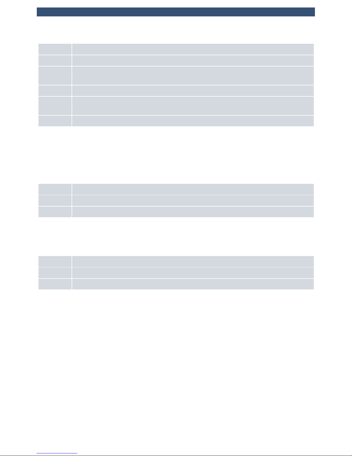
HSE
EXP
Intel®
APL
Atom™
PC -6TANGO
Mezzanine
2 x SATA 6G
Mezzanine
Legacy/LPC
PC6-TANGO EKF ekf.com•© •
CFast Socket
J1
J2
UHM
or
PICMG® 2.30
Rear I/O
Module
PICMG® 2.0
CompactPCI®
Classic
CPCI-S.0
Periphe ral
Boards
J2
UHM
Dual
GbE
P-USB
P-ETH
P-FPH
P-DP1
J-GP
P-DP2
DP1
DP2
2 x
USB
3.0
© EKF
ekf.com
+
J-RTC
PC6-TANGO • System Expansion Options
Mezzanine Side Board Options
The PC6-TANGO is provided with several stacking connectors for attachment of a mezzanine
expansion module (aka side board), suitable for a variety of readily available mezzanine cards (please
refer to www.ekf.com/c/ccpu/mezz_ovw.pdf for a more comprehensive overview). EKF furthermore
offers custom specific development of side boads (please contact sales@ekf.de).
Most mezzanine expansion modules require an assembly height of 8HP in total, together with the
CPU carrier board (resulting from two cards at 4HP pitch each). In addition, cropped low profile mass
storage mezzanine modules can be attached to P-HSE, which maintain the 4HP envelope, for
extremely compact systems.
© EKF -41- ekf.com

PC6-TANGO • CompactPCI® PlusIO • Intel® Atom™ E39xx Processor (APL-I SoC)
Sample Mezzanine Side Card 8HP Assembly
Sample Low Profile Mezzanine Module 4HP Assembly
© EKF -42- ekf.com

PC6-TANGO • CompactPCI® PlusIO • Intel® Atom™ E39xx Processor (APL-I SoC)
P-EXP
I/F Type Controller
LPC (Low Pin Count) APL-I SoC
HD Audio APL-I SoC
I2C APL-I SoC (I2C Port 0)
2 x USB 2.0 APL-I SoC
UART Rx/Tx TTL APL-I SoC (UART Port 0)
P-HSE
I/F Type Controller
SATA1 APL-I SoC (Port 1)
SATA2 (Option) Option 88SE9170 SATA Controller (Port 0)
© EKF -43- ekf.com

PC6-TANGO • CompactPCI® PlusIO • Intel® Atom™ E39xx Processor (APL-I SoC)
CompactPCI® PlusIO
CompactPCI® PlusIO (PICMG® 2.30) is a standard for rear I/O across J2. High speed signal lines (PCI
Express®, SATA, Gigabit Ethernet and USB) are passed from the PC6-TANGO through the special
UHM J2 connector to the backplane, for usage either with a PlusIO rear I/O transition module, or
CompactPCI® Serial card slots.
CompactPCI® Serial (PICMG® CPCIS.0) defines a completely new card slot, based on PCI Express®,
SATA, Gigabit Ethernet and USB serial data lines. On a hybrid backplane, both card styles can reside,
CompactPCI® and CompactPCI® Serial, with the PC6-TANGO in the middle as controller for both
backplane segments.
The PC6-TANGO can be used in any system with a CompactPCI
®
PlusIO backplane according to the
PICMG® 2.30 specification. Hybrid backplanes allow the configuration of systems with CompactPCI
®
Serial slots in addition to classic CompactPCI® boards.
CompactPCI® PlusIO & CompactPCI® Serial
Hybrid Backplane
Removable Power Supply
CompactPCI 32-Bit
Peripheral Slots
CPCIS.0
Peripheral Slots
© •
EKF ekf.com
PICMG 2.30 PlusIO
®
Sample Small Systems Hybrid Backplane
© EKF -44- ekf.com

PC6-TANGO • CompactPCI® PlusIO • Intel® Atom™ E39xx Processor (APL-I SoC)
Sample Hybrid CompactPCI® & CompactPCI® Serial Backplanes
CompactPCI® PlusIO CPU Card as System Controller in a Hybrid System
Warning:
Do not operate the standard PC6-TANGO in systems with a 64-bit CompactPCI® backplane. The J2/P2
pin assignment of a 64-bit CPCI backplane differs substantially from a CompactPCI® PlusIO backplane,
which will result in an overvoltage or short circuit situation on several pins, causing permanent
damage to the PC6-TANGO. For use together with a 64-bit CompactPCI® classic backplane, special
PC6-TANGO versions are available on customer request, however supporting only 32-bit peripheral
cards. The use of 64-bit CompactPCI® classic peripheral boards may cause problems.
© EKF -45- ekf.com

PC6-TANGO • CompactPCI® PlusIO • Intel® Atom™ E39xx Processor (APL-I SoC)
Small CompactPCI® PlusIO Box
CompactPCI® PlusIO Rack
© EKF -46- ekf.com

PC6-TANGO • CompactPCI® PlusIO • Intel® Atom™ E39xx Processor (APL-I SoC)
As an alternate, the PC6-TANGO can be combined with a CompactPCI® PlusIO rear I/O transition
module, such as the PR1-RIO, which is provided with I/O connectors (on-board and back-panel) for all
high speed signals.
PR1-RIO • Rear I/O Transition Module
© EKF -47- ekf.com

PC6-TANGO • CompactPCI® PlusIO • Intel® Atom™ E39xx Processor (APL-I SoC)
Installing and Replacing Components
Before You Begin
Warnings
The procedures in this chapter assume familiarity with the general terminology associated with
industrial electronics and with safety practices and regulatory compliance required
for using and modifying electronic equipment. Disconnect the system from its
power sour ce an d from any telecommunication links, networks or
modems before performing any of the procedures described in this chapter. Failure
to disconnect power, or telecommunication links before you open the system or perform any
procedures can result in personal injury or equipment damage. Some parts of the system can continue
to operate even though the power switch is in its off state.
Caution
Electrostatic discharge (ESD) can damage components. Perform the procedures
described in this chapter only at an ESD workstation. If such a station is not available,
you can provide some ESD protection by wearing an antistatic wrist strap and
attaching it to a metal part of the system chassis or board front panel. Store the board
only in its original ESD protected packaging. Retain the original packaging (antistatic bag and
antistatic box) in case of returning the board to EKF for repair.
© EKF -48- ekf.com

PC6-TANGO • CompactPCI® PlusIO • Intel® Atom™ E39xx Processor (APL-I SoC)
Installing the Board
Warning
This procedure should be done only by qualified technical personnel. Disconnect the system from its
power source before doing the procedures described here. Failure to disconnect power, or
telecommunication links before you open the system or perform any procedures can result in personal
injury or equipment damage.
Typically you will perform the following steps:
C Switch off the system, remove the AC power cord
C Attach your antistatic wrist strap to a metallic part of the system
C Remove the board packaging, be sure to touch the board only at the front panel
C Identify the related CompactPCI® slot (peripheral slot for I/O boards, system slot for CPU
boards, with the system slot typically most right or most left to the backplane)
C Insert card carefully (be sure not to damage components mounted on the bottom side of the
board by scratching neighboured front panels)
C A card with onboard connectors requires attachment of associated cabling now
C Lock the ejector lever, fix screws at the front panel (top/bottom)
C Retain original packaging in case of return
© EKF -49- ekf.com

PC6-TANGO • CompactPCI® PlusIO • Intel® Atom™ E39xx Processor (APL-I SoC)
Removing the Board
Warning
This procedure should be done only by qualified technical personnel. Disconnect the system from its
power source before doing the procedures described here. Failure to disconnect power, or
telecommunication links before you open the system or perform any procedures can result in personal
injury or equipment damage.
Typically you will perform the following steps:
C Switch off the system, remove the AC power cord
C Attach your antistatic wrist strap to a metallic part of the system
C Identify the board, be sure to touch the board only at the front panel
C Unfasten both front panel screws (top/bottom), unlock the ejector lever
C Remove any onboard cabling assembly
C Activate the ejector lever
C Remove the card carefully (be sure not to damage components mounted on the bottom side
of the board by scratching neighboured front panels)
C Store board in the original packaging, do not touch any components, hold the board at the
front panel only
Warning
Do not expose the card to fire. Battery cells and other components could explode
and cause personal injury.
© EKF -50- ekf.com

PC6-TANGO • CompactPCI® PlusIO • Intel® Atom™ E39xx Processor (APL-I SoC)
EMC Recommendations
In order to comply with the CE regulations for EMC, it is mandatory to observe the following rules:
C The chassis or rack including other boards in use must comply entirely with CE
C Close all board slots not in use with a blind front panel
C Front panels must be fastened by built-in screws
C Cover any unused front panel mounted connector with a shielding cap
C External communications cable assemblies must be shielded (shield connected only at one end
of the cable)
C Use ferrite beads for cabling wherever appropriate
C Some connectors may require additional isolating parts
Recommended Accessories
Blind CPCI Front
Panels
EKF Elektronik Widths currently available
(1HP=5.08mm):
with handle 4HP/8HP
without handle
2HP/4HP/8HP/10HP/12HP
© EKF -51- ekf.com

PC6-TANGO • CompactPCI® PlusIO • Intel® Atom™ E39xx Processor (APL-I SoC)
Replacement of the Battery
When your system is turned off, a battery maintains the voltage to run the time-of-day clock and to
keep the values in the CMOS RAM.
Most versions of PC6-TANGO are delivered with a battery holder which allows easy replacement of the
coin cell. Be sure to use a BR2032 cell as spare part to ensure an extended temperature range. Be
careful when removing the old cell and inserting the new one.
For boards with a soldered battery the used battery must be desoldered, and the new one soldered.
For this case, we recommend strongly that you return the board to EKF for battery replacement.
Warning
Danger of explosion if the battery is incorrectly replaced or shorted. Replace only with
the same or equivalent type. Do not expose a battery to fire.
© EKF -52- ekf.com

PC6-TANGO • CompactPCI® PlusIO • Intel® Atom™ E39xx Processor (APL-I SoC)
Technical Reference
Local PCI Devices
The following table shows the on-board PCI devices and their location within the PCI configuration
space. Most devices are part of the APL-I SoC.
Bus # Device # Function # Vendor ID Device ID Description
0 0 0 0x8086 0x5AF0 APL SoC Host Bridge
0 2 0 0x8086 0x5A84 APL SoC Integrated Graphics Device
0 3 0 0x8086 0x5A88 APL SoC Imaging Unit
0 14 0 0x8086 0x5A98 APL SoC Audio
0 18 0 0x8086 0x5AE0 APL SoC SATA
0 19 0 0x8086 0x5AD8 APL SoC PCIe-A Port #0
0 19 1 0x8086 0x5AD9 APL SoC PCIe-A Port #1
0 19 2 0x8086 0x5ADA APL SoC PCIe-A Port #2
0 19 3 0x8086 0x5ADB APL SoC PCIe-A Port #3
0 20 0 0x8086 0x5AD6 APL SoC PCIe-B Port #0
0 20 1 0x8086 0x5AD7 APL SoC PCIe-B Port #1
0 21 0 0x8086 0x5AA8 APL SoC USB xHCI Controller
0 22 0 0x8086 0x5AAC APL SoC I2C Interface #0
0 22 1 0x8086 0x5AAE APL SoC I2C Interface #1
0 24 0 0x8086 0x5ABC APL SoC UART Interface #0
0 27 0 0x8086 0x5ACA APL SoC SDXC Host Controller
0 28 0 0x8086 0x5ACC APL SoC eMMC Controller
0 31 0 0x8086 0x5AE8 APL SoC LPC Bridge
0 31 1 0x8086 0x5AD4 APL SoC SMBus Controller
1
1)
0 0 0x12D8 0x2608 PCIe Switch Root Port (PI7C9X2G606)
2
1)
1,2,4 ... 0 0x12D8 0x2608 PCIe Switch Downstream Ports (PI7C9X2G606)
3
1)
0 0 0x8086 0x1533 Ethernet Controller NC2 (i210IT)
4
1)
0 0 0x8086 0x1533 Ethernet Controller NC1 (i210IT)
5
1)
0 0 0x8086 0x1533 Ethernet Controller NC4 (i210IT)
6
1)
0 0 0x8086 0x1533 Ethernet Controller NC3 (i210IT)
7
1)
0 0 0x1B4B 0x9170 SATA Host Controller (88SE9170)
1)
Bus number may vary depending on devices situated on the backplane and the PCI enumeration schema
implemented in UEFI/BIOS.
© EKF -53- ekf.com

PC6-TANGO • CompactPCI® PlusIO • Intel® Atom™ E39xx Processor (APL-I SoC)
Local SMB/I2C Devices
The PC6-TANGO contains devices that are attached to the APL-I SoC System Management Bus
(SMBus). These are the SPD EEPROM for the on-board memory, the PLD (MachXO2) glue logic
including a set of board control and status registers, the CPU PMIC, a PCIe clock buffer, a general
purpose serial EEPROM and two general purpose, non-volatile electronic jumpers.
Additional off-board devices may be addressed via discrete I2C master controllers provided by the
APL-I SoC. While the APL I2C port 0 is used on the mezzanine connector P-EXP, the APL I2C port 1 is
wired to the CompactPCI® backplane connector J1 for peripheral card usage. The separation in
different threads reduces considerably potential SMBus/I2C addressing conflicts.
Controller Address Description
SMBus 0x2E Board Control/Status (MachXO FPGA)
SMBus 0x2F Non-volatile Electronic Jumper
SMBus 0x50 SPD on-Board Memory
SMBus 0x57 Board ID EEPROM
SMBus 0x5E PMIC
SMBus 0x6B DB800 Clock Buffer
I2C[0]
1)
P-EXP (Pins 29/30)
I2C[1]
1)
CPCI Backplane Connector J1 (Pins B17/C17)
1)
Address depends on devices attached
© EKF -54- ekf.com

PC6-TANGO • CompactPCI® PlusIO • Intel® Atom™ E39xx Processor (APL-I SoC)
Board Control and Status Registers (BCSR)
A set of board control and status registers allow to program special features on the PC6-TANGO:
< Assert a full reset
< Control activity of front panel reset and power event button
< Program time-outs and trigger a watchdog
< Get access to two LEDs in the front panel
< Get power fail and watchdog status of last board reset
The register set consists of five registers located on the SMBus at Device ID=0x5c on the following
addresses:
< 0xA0: CMD_CTRL0_WR: Write to Control Register 0 (Write-Only)
< 0xA1: CMD_CTRL0_RD: Read from Control Register 0 (Read-Only)
< 0xB0: CMD_STAT0_WR: Write to Status Register 0 (Write-Clear)
< 0xB1: CMD_STAT0_RD: Read from Status Register 0 (Read-Only)
< 0xB2: CMD_STAT1_WR: Write to Status Register 1 (Write-Clear)
< 0xB3: CMD_STAT1_RD: Read from Status Register 1 (Read-Only)
< 0xC1: CMD_PLDREV_RD: Read from PLD Revision Register (Read-Only)
To prevent misfunction accesses to the registers should be done by SMBus “Byte Data” commands.
Further writes to read-only or reads to write-only registers should be omitted.
© EKF -55- ekf.com

PC6-TANGO • CompactPCI® PlusIO • Intel® Atom™ E39xx Processor (APL-I SoC)
Write/Read Control Register 0
Write: SMBus Address 0xA0 Default after reset: 0x00
Read: SMBus Address 0xA1
Bit Description CMD_CTRL0
7 GPLED
0=Green part of the front panel LED GP is off (Default)
1=Green part of the front panel LED GP is on
6 FPDIS
0=Enable the front panel handle switch (Default)
1=Disable the front panel handle switch
5 FERP#
0=The front panel handle switch generates a power event (Default)
1=The front panel handle switch generates a system reset
4:3 WDGT0:WDGT1
Maximum Watchdog retrigger time:
0:0 2 sec
1:0 10 sec
0:1 50 sec
1:1 250 sec
2 WDGTRG
Retrigger Watchdog. Any change of this bit will retrigger the watchdog.
After a system reset the watchdog is in an inactive state. The watchdog is armed on the 1
st
edge of this bit.
1 PGLED
0=Red part of the front panel LED PG is off (Default)
1=Red part of the front panel LED PG is blinking
0 SRES
0=Normal operation (Default)
1=A system reset is performed
© EKF -56- ekf.com

PC6-TANGO • CompactPCI® PlusIO • Intel® Atom™ E39xx Processor (APL-I SoC)
Read/Clear Status Register 0
Write: SMBus Address 0xB0
Read: SMBus Address 0xB1
Bit Description CMD_STAT0
7 PF18S
0=Normal operation
1=Last system reset may be caused by a power failure of the +V1.8S voltage regulator
6 RESERVED
Always read as 0
5 RESERVED
Always read as 0
4 PF135S
0=Normal operation
1=Last system reset may be caused by a power failure of the +V1.35S4 voltage regulator
3 RESERVED
Always read as 0
2 RESERVED
Always read as 0
1 RESERVED
Always read as 0
0 RESERVED
Always read as 0
The bits in this register are sticky, i.e. their state will be kept even if a system reset occurs. To clear the
bits a write to the register with arbitrary data may be performed.
© EKF -57- ekf.com

PC6-TANGO • CompactPCI® PlusIO • Intel® Atom™ E39xx Processor (APL-I SoC)
Read/Clear Status Register 1
Write: SMBus Address 0xB2
Read: SMBus Address 0xB3
Bit Description CMD_STAT1
7 WDGARMD
0=Normal operation
1=The watchdog is armed and has to be retriggered within its time-out period
6 WDGRST
0=Normal operation
1=Last system reset may be caused by a watchdog time-out
5 WDGHT
0=Normal operation
1=The watchdog already has elapsed half of its time-out period
4 PF12A
0=Normal operation
1=The +V12A voltage rail is not present in the system
3 PF5S
0=Normal operation
1=Last system reset may be caused by a power failure of the +V5S voltage regulator
2 RESERVED
Always read as 0
1 RESERVED
Always read as 0
0 PF33S
0=Normal operation
1=Last system reset may be caused by a power failure of the +V3.3S voltage regulator
Except of WDGHT and WDGARMD the bits in this register are sticky, i.e. their state will be kept even
if a system reset occurs. To clear the bits a write to the register with arbitrary data may be performed.
© EKF -58- ekf.com

PC6-TANGO • CompactPCI® PlusIO • Intel® Atom™ E39xx Processor (APL-I SoC)
Read PLD Revision Register
Write: Not allowed
Read: SMBus Address 0xC1
Bit Description CMD_PLDREV
7:0 PLDREV
Read PLD Revison Number
© EKF -59- ekf.com

PC6-TANGO • CompactPCI® PlusIO • Intel® Atom™ E39xx Processor (APL-I SoC)
GPIO Usage
GPIO Usage APL-I SoC
GPIO Usage APL-I SoC
GPIO Type Function Description
0-15 I N/A Not connected on PC6
16 O GP_LED_RED General Purpose Red LED Control (via PLD)
17 I CPCI_FAL CompactPCI Power Failure Line CPCI_FAL# via inverting level shifter
18 O CPCI_INTS_EN LOW: Isolate SERIRQ from CPCI_INTS
HIGH: Connect SERIRQ to CPCI_INTS
19 O SE_SYS_WP General Purpose Serial EEPROM Write Protection
20 O TPM_PP TPM2.0 Physical Present Pin
21 O ENABLE_NC3 Enable Ethernet Controller NC3
22 O ENABLE_NC4 Enable Ethernet Controller NC4
23 O ENABLE_NC1 Enable Ethernet Controller NC1
24 O ENABLE_NC2 Enable Ethernet Controller NC2
25 I GP_JUMP# Reset UEFI/BIOS Setup to Factory Defaults, Jumper J-GP
26 O SATA_SOC_ACT# Native: Signal APL SATA activity via green HD LED in Front Panel (via
PLD)
27 O PPSM_EN Connect IEEE 1588 PPS/PPM to J-GP and CompactPCI
®
J2
LOW: PPS/PPM disconnected from J-GP and J2
HIGH: PPS/PPM connected to J-GP and J2
28-31 I BOARD_CFG Board Configuration Jumpers BOARD_CGF[0:3]
32 O USB_FP1_PEN USB Front Panel Right Port Power Enable
33 O USB_FP2_PEN USB Front Panel Left Port Power Enable
183 I EXP_SMI# Expansion Interface SMI Request (from P-EXP Pin 15 via level shifter)
ISH 0 O SOC_HDA_BCLK Native: HD Audio BCLK (to P-EXP Pin 37 via level shifter)
ISH 1 O SOC_HDA_SYNC Native: HD Audio SYNC (to P-EXP Pin 36 via level shifter)
ISH 2 I SOC_HDA_SDI Native: HD Audio IN (from P-EXP Pin 34 via level shifter)
ISH 3 O SOC_HDA_SDO Native: HD Audio OUT (to P-EXP Pin 33 via level shifter)
ISH 4-6 I HW_REV PCB Revision Code HW_REV[2:0]:
GPIO[6:4] 000 001 010 ... 111
Revision 012...7
ISH 7 I CPCI_ENUM# CompactPCI System Enumeration Line ENUM# (from J1 Pin C25 via
level shifter)
ISH 8 I CPCI_INTP CompactPCI Interrupt Request Line CPCI_INTP (from J1 Pin E4 via
level shifter)
© EKF -60- ekf.com

PC6-TANGO • CompactPCI® PlusIO • Intel® Atom™ E39xx Processor (APL-I SoC)
GPIO Usage APL-I SoC
GPIO Type Function Description
ISH 9 O SPEAKER Native: Speaker output (to P-EXP Pin 39 via MOSFET)
© EKF -61- ekf.com

PC6-TANGO • CompactPCI® PlusIO • Intel® Atom™ E39xx Processor (APL-I SoC)
J-GP UEFI/BIOS Defaults & IEEE 1588 Pulse per Second
The jumper J-GP may be used to reset the UEFI/BIOS configuration settings to a default state. The
UEFI/BIOS on PC6-TANGO stores most of its settings in an area within the UEFI/BIOS flash, e.g. the
actual boot devices. Using the jumper J-GP is only necessary, if it is not possible to enter the setup of
the UEFI/BIOS. To reset the settings mount a jumper on J-GP and perform a system reset. As long as
the jumper is stuffed the UEFI/BIOS will use the default configuration values after any system reset. To
get normal operation again, the jumper has to be removed.
There is also an alternate function available on J-GP. Pin 1 of this jumper carries a TTL level Pulse per
Second (PPS) signal according the IEEE 1588 specification when enabled by UEFI/BIOS settings. A wire
may be connected to trigger events on external devices.
NOTE: The PPS TTL level signal is also available via the CompactPCI
®
PlusIO connector J2 pin D14
(SATA-SCL), for rear I/O usage (must be enabled by GPIO27 of the APL-I SoC).
J-GP Function
Jumper Removed 1)Normal operation
Jumper Installed UEFI/BIOS configuration reset performed
1)
This setting is the factory default
1
J-GP
© EKF -62- ekf.com

PC6-TANGO • CompactPCI® PlusIO • Intel® Atom™ E39xx Processor (APL-I SoC)
Manufacturer Mode Jumper (J-MFG)
The jumper J-MFG is used to bring the board into the manufacturer mode. This is necessary only on
board production time and should not used by customers. For normal operation the jumper should
be removed. The pin header J-MFG is not stuffed on the PC6-TANGO by default.
J-MFG Function
Jumper Removed 1)Normal operation
Jumper Installed Entering Manufacturer Mode
1)
This setting is the factory default
1
J-MFG
© EKF -63- ekf.com

PC6-TANGO • CompactPCI® PlusIO • Intel® Atom™ E39xx Processor (APL-I SoC)
RTC Reset (J-RTC)
The jumper J-RTC may be used to reset certain register bits of the battery backed RTC core within the
APL-I SoC. This can be necessary under rare conditions (e.g. battery undervoltage), if the CPU fails to
enter the UEFI/BIOS POST after power on. Note that installing of jumper J-RTC will neither set
UEFI/BIOS Setup to EKF Factory Defaults nor resets the time and date register values of the RTC (Real
Time Clock). To reset the RTC core the board must be removed from the system rack. Short-circuit the
pins of J-RTC for about 1 sec. Thereafter reinstall the board to the system and switch on the power.
It is important to accomplish the RTC reset while the board has no power. The pin header J-RTC is not
stuffed on the PC6-TANGO by default.
J-RTC Function
Jumper Removed 1)Normal operation
Jumper Installed RTC reset performed
1)
This setting is the factory default.
1
J-RTC
© EKF -64- ekf.com

PC6-TANGO • CompactPCI® PlusIO • Intel® Atom™ E39xx Processor (APL-I SoC)
Connectors
Caution
Some of the internal connectors provide operating voltage (3.3V, 5V and 12V) to devices inside the
system chassis, such as internal peripherals. Not all of these connectors are short circuit protected. Do
not use these internal connectors for powering devices external to the computer chassis. A fault in the
load presented by the external devices could cause damage to the board, the interconnecting cable
and the external devices themselves.
© EKF -65- ekf.com

PC6-TANGO • CompactPCI® PlusIO • Intel® Atom™ E39xx Processor (APL-I SoC)
PG
GP
DP
2
DP
1
PC6-TANGO
©
••E
K
F draft - do not scale ekf.co
m
HD
RB
USB
OT
SD
2
GbE
1
EB
P01-M12
PG
GP
DP
2
DP
1
PC6-TANGO
©
••EKF draft - do not scale ekf.co
m
GbE
HD
RB
2
1
USB
OT
SD
EB
Front Panel Connectors
The PC6-TANGO front panel is provided with dual receptacles for monitors (DisplayPort), USB devices
(Type-A 5Gbps), and networking (RJ45 GbE). In addition, a Micro SD card slot is available.
As an ordering option, the RJ45 jacks can be replaced by M12 X_coded receptacles, which requires an
8HP front panel assembly in combination with a small mezzanine module P01-M12.
© EKF -66- ekf.com

PC6-TANGO • CompactPCI® PlusIO • Intel® Atom™ E39xx Processor (APL-I SoC)
DisplayPort Connectors
The Intel® CoreTM processors used on PC6-TANGO are equipped with an integrated graphics
controller, which supports DisplayPort interfaces permitting simultaneous independent operation of
multiple displays. Two DP receptacles are available from the PC6-TANGO front panel.
DisplayPort P-DP1/2
20 PWR
1)
19 RETURN (GND)
18 HPD 17 AUX_CH(N)
16 GND 15 AUX_CH(P)
14 CONFIG2 (GND) 13 CONFIG1
12 LANE3(N) 11 GND
10 LANE3(P) 9 LANE2(N)
8GND7LANE2(P)
6LANE1(N)5 GND
4 LANE1(P) 3 LANE0(N)
2GND1LANE0(P)
1)
+3.3V via current-limited electronic power switch. This voltage is switched on in S0 state only.
Most professional monitors are equipped with a DisplayPort connector input. For attachment of either
VGA, DVI or HDMI type display to the PC6-TANGO, there are suitable adapters and also adapter
cables available.
For rugged applications, DisplayPort cable assemblies with a connector latching mechanism are
recommended.
EKF Part # 270.60.20.0 •
©
EKF
20
© EKF -67- ekf.com

PC6-TANGO • CompactPCI® PlusIO • Intel® Atom™ E39xx Processor (APL-I SoC)
USB Connectors
The Intel® APL-I SoC incorporates an USB 3.0 xHCI host controller (USB 3.1 Gen1 SuperSpeed 5Gbps).
Two ports are directly available on the PC6-TANGO front panel (type A receptacle), for attachment of
external USB devices.
P-USB • Dual USB 3.0 Receptacle
USB 3.0 dual Type-A receptacle, stacked, 18-position
1 VBUS +5V, 1.5A max
1)
2USB D-
3USB D+
4GND
5SS RX-
6 SS RX+
7GND
8 SS TX-
9SS TX+
1)
+5V via 1.5A current-limited electronic power switch. Power rail may be switched off by software
independently for each port.
For rugged applications EKF offers custom specific USB cable connector retainer solutions (similar
picture below).
USB 3.
0
#
2
7
0.23.1
8.2
© EKF • ekf.com
1
2
© EKF -68- ekf.com

PC6-TANGO • CompactPCI® PlusIO • Intel® Atom™ E39xx Processor (APL-I SoC)
1
1
270.02.08.5
Ethernet Connectors RJ45
All Ethernet ports on the PC6-TANGO are based on individual I210IT PCIe to Ethernet controllers, i.e.
offer different MAC addresses, hence suitable for simple network attachment or flexible usage as
router or gateway. The IEEE 1588 PPS signal (refer to backplane connector J2) is derived from the
NIC1 which is wired to the upper RJ45 connector (Port 1).
Gigabit Ethernet Ports 1/2 (P-ETH, RJ-45)
Port 1
IEEE 1588
PPS
1NC1_MDX0+
2NC1_MDX0-
3NC1_MDX1+
4NC1_MDX2+
5NC1_MDX2-
6NC1_MDX1-
7NC1_MDX3+
8NC1_MDX3-
Port 2
1NC2_MDX0+
2NC2_MDX0-
3NC2_MDX1+
4NC2_MDX2+
5NC2_MDX2-
6NC2_MDX1-
7NC2_MDX3+
8NC2_MDX3-
The lower green LED of each front panel connector indicates LINK established when continuously on,
and data transfer (activity) when blinking. If the lower green LED is permanently off, no LINK is
established. The upper green/yellow dual-LED signals the link speed 1Gbit/s when lit yellow, 100Mbit/s
when lit green, and 10Mbit/s when off.
© EKF -69- ekf.com

PC6-TANGO • CompactPCI® PlusIO • Intel® Atom™ E39xx Processor (APL-I SoC)
Option M12 X-Coded Ethernet Receptacles
As an ordering option, the RJ45 jacks can be replaced by M12 X-coded receptacles. A small
mezzanine module (P01-M12) is soldered to the RJ45 footprint, resulting in an 8HP front panel
assembly.
M12 X-Coded Front Panel I/O Receptacles
Gigabit Ethernet • 271.12.008.20 • M12-X Flush-type socket
Ports
1-2
1MDX0+
2MDX0-
3MDX1+
4MDX1-
5MDX3+
6MDX3-
7MDX2-
8MDX2+
The pin numbers of an M12 X-coded connector do not reflect the RJ45 Gigabit Ethernet signal
assignment. For cross-over patch cables M12 to RJ45 please refer to the table below.
M12 X Signal Colors T568B RJ45
1 MDX0+ white/orange 1
2 MDX0- orange 2
3 MDX1+ white/green 3
4 MDX1- green 6
5 MDX3+ white/brown 7
6 MDX3- brown 8
7 MDX2- white/blue 5
8 MDX2+ blue 4
Suitable industrial Gigabit Ethernet M12 cable assemblies can be ordered from EKF, or directly from
well-known cable and connector manufacturers e.g. Metz, Phoenix, Escha and many others.
Ordering Information Cable Assemblies
Gigabit Ethernet cable M12 to M12: #271.14.008.xx (xx=length/meter)
Gigabit Ethernet cable M12 to RJ-45: #271.15.008.xx (xx=length/meter)
18
271.12.008.00
© EKF • ekf.com
Draft - Do Not Scale
© EKF -70- ekf.com

PC6-TANGO • CompactPCI® PlusIO • Intel® Atom™ E39xx Processor (APL-I SoC)
HSE
EXP
Intel®
APL
Atom™
PC -6TANGO
PC6-TANGO EKF ekf.com•© •
CFast Socket
J1
J2
UHMJ2UHM
Dual
GbE
P-USB
P-ETH
P-FPH
P-DP1
J-GP
P-DP2
DP1
DP2
2 x
USB
3.0
© EKF
ekf.com
+
J-RTC
MAGMOD 8MAGMOD 8MAGMOD 8MAGMOD 8MAGMOD 8MAGMOD 8MA GMOD 8MAGMOD 8
P-01 M12
Simplified Block Diagram
P01-M12
Mezzanine Module
Front
Panel
I/O
4HP
GbE
2
1
GbE
4HP
© EKF -71- ekf.com

PC6-TANGO • CompactPCI® PlusIO • Intel® Atom™ E39xx Processor (APL-I SoC)
PG
GP
DP
2
SD
DP
1
PC6-TANGO
©
••EKF draft - d
o no
t scale ekf.c
o
m
GbE
HD
EB
RB
2
1
USB
OT
Micro SD
Bottom
Side
microSD Card Holder
The PC6-TANGO is provided with a front panel microSD card slot (push-push type, w. card detect
switch).
microSDHC Host Connector • 218.6.010.1
1DAT2
2DAT3
3CMD
4 +3.3V
5CLK
6GND
7DAT0
8DAT1
© EKF -72- ekf.com

PC6-TANGO • CompactPCI® PlusIO • Intel® Atom™ E39xx Processor (APL-I SoC)
CFast™ Socket w. Card Retainer Clip
CFast™ Card Holder
By default, the PC6-TANGO is provided with a CFast™ host connector. It is suitable for CFast™ cards,
which have the same dimensions as CompactFlash™ cards, but are operated in SATA mode. Industrial
CFast™ SSD cards are available up to 256GB as of current. The SATA channel available on the CFast™
socket is derived directly from the APL-I SoC (SATA port 0). Since SATA based SSD modules are fast
and reliable over the industrial temperature range, a CFast™ card can be used as boot device in many
applications.
A guiding rail is provided to simplify card insertion. Once installed, the CFast™ card will have to be
locked. This can be done either by a retainer latch, in order to withstand shock and vibration. The
latching part may be supplied loosely (not assembled on the PC6-TANGO, depending on your order),
and hence must be snapped onto the CFast™ socket first, before being used (similar picture below).
As an alternate, when the PC6-TANGO is combined with a low profile mezzanine module such as the
C48-M2, the latching retainer will be replaced by a small mounting block, fixed by a screw on th PCB
bottom side.
If the CFast™ host connector is not in use in an application, please remove the latching retainer
assembly carefully from the socket (strut the snap-in clips on both sides). As an alternate, use an
adhesive tape to fix the CFast™ retaining lever in its normal (locking) position. Otherwise, under worst
conditions, the latching spring could cause a short circuit situation when unintentionally moving
(forced by shock or vibration) and touching a PCB in the neighboured board slot of the system rack.
© EKF -73- ekf.com

PC6-TANGO • CompactPCI® PlusIO • Intel® Atom™ E39xx Processor (APL-I SoC)
The fixation alternate of the CFast™ card is a small L-shape mounting block (similar picture below).
The threaded mounting element is fastened by a metric screw (M2x4) from the bottom side of the
PCB.
There is some ambiguity about the top and bottom side of a CFast™ module - be sure to insert the
card properly into the socket. For several CFast™ SSD card brands this would require the module to be
inserted with its label facing downwards (to the PCB). However, leading suppliers (e.g. Swissbit)
attach the label vice versa on their cards, which requires that such CFast™ modules have to be
inserted with their label on top. Anyway, the finger grip, which is recessed into the cards end, should
be up. Forced wrong insertion may cause permanent damage to the CFast™ card and the CFast™ host
connector.
CFast™ Card Locking Alternates
Retainer lever (can be actuated by hand w/o tool) EKF part no. 218.5.024.29
Mounting block (screw driver required for fastening and release) EKF part no. 710.9.CFA.B
CFast™ Card Fixation w. Mounting Block
© EKF -74- ekf.com

PC6-TANGO • CompactPCI® PlusIO • Intel® Atom™ E39xx Processor (APL-I SoC)
P-CF CFast™ Host Connector • 218.5.024.21
S1 GND
S2 SATA_TXP (A+)
S3 SATA_TXN (A-)
S4 GND
S5 SATA_RXN (B-)
S6 SATA_RXP (B+)
S7 GND
PC1 CDI (GND)
PC2 GND
PC3
DEVSLP
PC4
NC
PC5
NC
PC6
NC
PC7 GND
PC8
LED1
PC9
LED2
PC10
RSVD
PC11
RSVD
PC12
IFDet
PC13 +3.3V 1)
PC14 +3.3V 1)
PC15 GND
PC16 GND
PC17 CDO 2)
signals italic/grey: NC
1) Overcurrent protected by electronic power switch (1.5A)
2) Used to enable the electronic power switch when card is fully inserted
SATA Rx/Tx signal direction as seen by the SATA host controller (APL-I SoC P0)
Part No. 218.5.024.21 CFast™ Host Connector
•
© EKF • ekf.com
© EKF -75- ekf.com

PC6-TANGO • CompactPCI® PlusIO • Intel® Atom™ E39xx Processor (APL-I SoC)
PC6-TANGO w. Low Profile Mezzanine Modul HSE Connector Based (Similar Picture)
Mezzanine Connectors
The PC6-TANGO is equipped with two connectors for optional mezzanine expansion. The connector
P-HSE is used for SATA based mass storage, available as low profile module (4HP assembly), e.g.
C48-M2 (dual M.2 SATA SSD). The legacy connector P-EXP is provided mainly for custom specific side
card design (8HP assembly).
WARNING: The +3.3V, +5V and +12V power pins of both mezzanine connectors P-EXP and P-HSE
are not protected against a short circuit event. These connectors therefore should be used only for
attachment of an approved expansion side card or low profile mezzanine module. The maximum
current flow across these pins should be limited to 1A per power pin via P-HSE and 0.5A maximum
across P-HSE pins.
© EKF -76- ekf.com

PC6-TANGO • CompactPCI® PlusIO • Intel® Atom™ E39xx Processor (APL-I SoC)
Expansion Interface P-EXP
P-EXP
GND 1 2 +3.3V
1)
CLK (25MHz) 3 4 RST#
LPC_AD056LPC_AD1
LPC_AD278LPC_AD3
LPC_FRAME# 9 10
NC
GND 11 12 +3.3V
1)
LPC_SERIRQ 13 14
NC
EXP_SMI# 15 16 SIO_CLK (14.3MHz)
UART0_TXD
3)
17 18 UART0_RXD
3)
NC
19 20
NC
GND 21 22 +5V
1)
USB_EXP2- 23 24 USB_EXP1-
USB_EXP2+ 25 26 USB_EXP1+
USB_EXP_OC# 27 28 EXP_RST#
I2C_SCL
2)
29 30 I2C_SDA
2)
GND 31 32 +5V
1)
HDA_SDOUT 33 34 HDA_SDIN
HDA_RST# 35 36 HDA_SYNC
HDA_CLK 37 38
NC
SPEAKER 39 40 +12V
4)
1)
Power rail switched on in state S0 only
2)
Connected to APL-I SoC I2C port 0 (this I/F is separated from the local SMBus I/F)
3)
TTL level signal, via level shifter to APL-I SoC
4)
Only in systems which provide +12V via backplane (+/-12V are not necessary to operate
PC6-TANGO)
21
1.27mm
Socket
40
© EKF 276.53.040.01 ekf.co
m
© EKF -77- ekf.com

PC6-TANGO • CompactPCI® PlusIO • Intel® Atom™ E39xx Processor (APL-I SoC)
High Speed Expansion Connector P-HSE
High Speed Expansion P-HSE
GND a1 b1 GND
SATA_HSE1_TXP
4)
a2 b2
NC
SATA_HSE1_TXN
4)
a3 b3
NC
GND a4 b4 GND
SATA_HSE1_RXN
4)
a5 b5
NC
SATA_HSE1_RXP
4)
a6 b6
NC
GND a7 b7 GND
SATA_HSE2_TXP
5)
a8 b8
NC
SATA_HSE2_TXN
5)
a9 b9
NC
GND a10 b10 GND
SATA_HSE2_RXN
5)
a11 b11
NC
SATA_HSE2_RXP
5)
a12 b12
NC
GND a13 b13 GND
NC
a14 b14
NC
NC
a15 b15
NC
GND a16 b16 GND
NC
a17 b17
NC
NC
a18 b18
NC
GND a19 b19 GND
NC
a20 b20
NC
NC
a21 b21
NC
+3.3VS
1)
a22 b22 +5VS
1)
+3.3VS
1)
a23 b23 +5VS
1)
+3.3VA
2)
a24 b24 +5VA
2)
+12V
3)
a25 b25 +12V
3)
1)
Power rail switched on in state S0 only (switched)
2)
Power rail on when system power supply is up
3)
Only in systems which provide +12V via backplane (+/-12V are not necessary to operate
PC6-TANGO)
4)
SATA 1 channel derived from the APL-I SoC SATA controller
5)
SATA 2 channel derived from the optional 88SE9170 SATA controller
All TX/RX signal directions with respect to the SATA controller.
a1
s1
s9 s18
s10
a25
b25
b1
1.00mm Pitch High Speed Female Connector (H=8mm)
© EKF • 275.90.08.068.01 • ekf.co
m
© EKF -78- ekf.com

PC6-TANGO • CompactPCI® PlusIO • Intel® Atom™ E39xx Processor (APL-I SoC)
C48-M2 Mezzanine Storage Module Based on the Connector HSE
C47-MSATA Mezzanine Storage Module Based on the Connector HSE
© EKF -79- ekf.com

PC6-TANGO • CompactPCI® PlusIO • Intel® Atom™ E39xx Processor (APL-I SoC)
Pin Headers & Debug
Front Panel Handle Microswitch Header P-FPH
The jumper P-FPH is used for attachment of an external SPDT switch. By default, P-FPH is connected
across a short cable harness to a microswitch, which is integrated into the PC6-TANGO front panel
handle (ejector lever). The switch performs a power button event (e.g. system shutdown) by shortcircuiting the pins 1 and 3 of P-FPH when activated (hold unlock button of front panel handle
depressed momentarily).
P-FPH
1 black Microswitch Pole (Common), Wired to PLD
2 red Microswitch Throw - F/P Handle Locked Position, not connected
3 yellow Microswitch Throw - F/P Handle Unlocked Position, Wired to GND
# 276.02.003.11
© EKF • ekf.com
1
© EKF -80- ekf.com

PC6-TANGO • CompactPCI® PlusIO • Intel® Atom™ E39xx Processor (APL-I SoC)
PLD Programming Header P-PLD
The PC6-TANGO is provided with a powerful PLD (Programmable Logic Device) which replaces legacy
glue logic. The programming header P-PLD is not stuffed (in use for manufacturing only). Its footprint
is situated at the bottom side of the board.
P-PLD
1 +3.3V
2TDO
3TDI
4
NC
5
KEY
6TMS
7GND
8TCK
240.1.08.I • © EKF • ekf.com
key
© EKF -81- ekf.com

PC6-TANGO • CompactPCI® PlusIO • Intel® Atom™ E39xx Processor (APL-I SoC)
Firmware Programming Header P-SPI
The PC6-TANGO firmware (UEFI/BIOS, Intel® TXE) is stored in a Serial Flash memory. Updates are
normally done by software. For debug and manufacturing a pin header P-SPI is provided (not stuffed
by default) at the bottom side of the board.
P-SPI
1 +1.8V
2SPI_SO
3SPI_SI
4PROG_EN#
5SPI_CS#
6
KEY
7GND
8SPI_CK
240.1.08. I • © EKF • ekf.comSP
key
© EKF -82- ekf.com

PC6-TANGO • CompactPCI® PlusIO • Intel® Atom™ E39xx Processor (APL-I SoC)
Processor Debug Header P-MIPI
The PC6-TANGO can be equipped with a 60-position processor debug header for JTAG based hardand software debugging (Samtec QSH series connector aka MIPI-60 specified by the MIPI Alliance
Debug Working Group *). The connector is suitable to attach a debugger (emulator) e.g. Lauterbach.
The header P-MIPI resides on the PCB bottom side, but is not stuffed by default.
P-MIPI Processor Debug Connector • 275.83.05.060.01
1 VREF_DEBUG (1.8V) TMS/TMSC 2
3 TCK TDO/EXTA 4
5 TDI/EXTB RESET# 6
7 RTCK/EXTC TRST#_PD 8
9 TRST#/EXTD EXTE/TRIGIN/PREQ# 10
11 EXTF/TRIGOUT/PRDY# VREF_TRACE (1.8V) 12
13
TRC_CLK0 TRC_CLK1
14
15 TARGET PRESENCE DETECT GND 16
17 GND
TRC_DATA000 TRC_DATA100
18
19
TRC_DATA001 TRC_DATA101
20
21
TRC_DATA002 TRC_DATA102
22
23
TRC_DATA003 TRC_DATA103
24
25
TRC_DATA004 TRC_DATA104
26
27
TRC_DATA005 TRC_DATA105
28
29
TRC_DATA006 TRC_DATA106
30
31
TRC_DATA007 TRC_DATA107
32
33
TRC_DATA008 TRC_DATA108
34
35
TRC_DATA009
POD_BOOT_HALT#
TRC_DATA109
36
37
TRC_DATA010
POD_HOOK
TRC_DATA110
38
39
TRC_DATA011
POD_PWRBTN#
TRC_DATA111
40
41
TRC_DATA012 TRC_DATA112
42
43
TRC_DATA013 TRC_DATA113
44
45
TRC_DATA014 TRC_DATA114
46
47
TRC_DATA015 TRC_DATA115
48
49
TRC_DATA016 TRC_DATA116
50
51
TRC_DATA017 TRC_DATA117
52
53
TRC_DATA018 TRC_DATA118
54
55
TRC_DATA019 TRC_DATA119
56
57 GND GND 58
59
TRC_CLK3 TRC_CLK2
60
pins grey/italic are pulled to GND
* MIPI01 MIPI Alliance Recommendation for Debug and Trace Connectors, version 1.10.00
© EKF -83- ekf.com

PC6-TANGO • CompactPCI® PlusIO • Intel® Atom™ E39xx Processor (APL-I SoC)
HSE
EXP
Intel®
APL
Atom™
PC -6TANGO
PC6-TANGO EKF ekf.com•© •
J2
UHMJ2UHM
Dual
GbE
P-USB
P-ETH
J-POW
+5V
P-FPH
P-DP1
J-GP
P-DP2
DP1
DP2
2 x
USB
3.0
© EKF
ekf.com
+
J-RTC
CFast Socket
™
Power Terminal Block
This option is provided for professional system integrators only
For stand-alone applications, the J1 backplane connector can be replaced on request by a two-circuit
terminal block, suitable for attachment (screw connection) of stranded wires up to 1mm2. The power
supply must provide +5V according to the CompactPCI® specification (+5%/-3%, <50mVpp ripple).
The PC6-TANGO may or may not be equipped with the backplane connector J2 for stand-alone
operation (option rear I/O module via J2). Note that in this configuration the platform reset signal is
missing (located on J1 pin C5). Using an adapted programming of the PLD on PC6-TANGO could solve
this problem. Please discuss your needs with sales@ekf.de before ordering.
CAUTION: The PC6-TANGO is not equipped with a protection circuitry against inverted wires. A
mistake will inevitably destroy the board caused by the interchanged polarity. Be extremely careful
while installation.
© EKF -84- ekf.com

PC6-TANGO • CompactPCI® PlusIO • Intel® Atom™ E39xx Processor (APL-I SoC)
Backplane Connectors
The backplane connector suite is comprised of two hard metric 2.0mm connectors. While the J1
connector is compliant to CompactPCI® PICMG® 2.0, the J2 connector pin assignment follows an
enhancement specification named CompactPCI® PlusIO PICMG® 2.30. This allows to combine classic
CompactPCI® peripheral cards (32bit PCI) and modern CompactPCI® Serial cards according to
PICMG® CPCI-S.0 on a common hybrid backplane.
1
25
J1 2
m
m
Hard
M
etric Connector
© EKF 250.0525.10.01 ekf.com
©
EKF 250.0522.10.10 ekf.com
1
22
J2 2mm Hard Metric Connector
aabbccddeef
f
© EKF -85- ekf.com

PC6-TANGO • CompactPCI® PlusIO • Intel® Atom™ E39xx Processor (APL-I SoC)
CompactPCI J1
J1 A B C D E
25 5V REQ64#
2)
ENUM#
1)
3.3V
9)
5V
24 AD1 5V V(I/O) AD0 ACK64#
2)
23 3.3V
9)
AD4 AD3 5V AD2
22 AD7 GND 3.3V
9)
AD6 AD5
21 3.3V
9)
AD9 AD8
M66EN
7)
C/BE0#
20 AD12 GND V(I/O) AD11 AD10
19 3.3V
9)
AD15 AD14 GND AD13
18 SERR#
1)
GND 3.3V
9)
PAR C/BE1#
17 3.3V
9)
IPMB SCL
3)
IPMB SDA
3)
GND PERR#
1)
16 DEVSEL#
1)
GND V(I/O) STOP#
1)
LOCK#
1)
15 3.3V
9)
FRAME#
1)
IRDY#
1)
BD_SEL#
6)
TRDY#
1)
14
KEY AREA (not keyed)
13
12
11 AD18 AD17 AD16 GND C/BE2#
10 AD21 GND 3.3V
9)
AD20 AD19
9C/BE3#NC
IDSEL
AD23 GND AD22
8 AD26 GND V(I/O) AD25 AD24
7 AD30 AD29 AD28 GND AD27
6REQ# 1)GND 3.3V
9)
CLK AD31
5
BRSVP1A5
4)
BRSVP1B5
4)
RST# GND GNT#
4
IPMB PWR (+5V)
3)
GND
HEALTHY#
V(I/O) INTP
1)
INTS
1)
3 INTA#
1)
INTB#
1)
INTC#
1)
5V INTD#
1)
2
TCK
4)
5V
TMS
4)
TDO
4)
TDI
4)
1 5V -12V
5)
TRST#
4)
+12V
8)
5V
signals marked grey/italic are not connected
© EKF -86- ekf.com

PC6-TANGO • CompactPCI® PlusIO • Intel® Atom™ E39xx Processor (APL-I SoC)
1) Various PCI control signals pulled up with 1kS to V(I/O). This value is specified for +5V V(I/O)
but works as well with +3.3V V(I/O) under all environments which have been tested by EKF.
On request, 2.7kS P/U resistors can be stuffed.
2) REQ64# and ACK64# not used on PC6-TANGO, though pulled up with 1kS to V(I/O).
3) IPMB SCL and SDA connected to APL-I SoC I2C port 1 via level shifter, pulled up with 2.7k to
J1 pin A4 IPMB_PWR (+5V). IPMB_PWR can be sourced externally, and is also supplied by the
PC6-TANGO across a Schottky diode.
4) All JTAG pins are NC since discouraged by CPCI specification Rev. 3.0
5) -12V connected to a decoupling capacitor only and not used on PC6-TANGO
6) BD_SEL# connected to PLD input, however not in logical use by default
7) M66EN is detected by the PCI bridge in order to allow either 66MHz PCI backplane operation,
or when pulled low (by peripheral board) forces 33MHz clock. Please note that the PCI bridge
can be setup also for 50MHz and 25MHz on customer request (resistor stuffing option). When
operating in 66MHz (50MHz) a V(I/O) voltage of +3.3V is mandatory.
8) +12V passed through to mezzanine connectors P-HSE and P-EXP, not required for
PC6-TANGO basic operation
9) The 3.3V pins can be sourced by the PC6-TANGO itself (power output via resettable fuse 2.0A),
for +5V only power supply designs (consider power 3.3V power requirements of peripheral
boards).
© EKF -87- ekf.com

PC6-TANGO • CompactPCI® PlusIO • Intel® Atom™ E39xx Processor (APL-I SoC)
CompactPCI J2 (PlusIO)
This connector is a high speed UHM connector, suitable for Gigabit Serial I/O. Refer also to PICMG®
2.30 CompactPCI® PlusIO Specification.
Please note, that the CompactPCI® PlusIO specification refers to SATA data rates of 1.5Gbps and
3Gbps. EKF has tested successfully also 6G over the backplane with sample devices, but cannot
guarantee this data rate under any condition. Other devices and other backplane brands/types in use
may cause a different result. Hence, for optimum reliability, the Marvell SATA controller will be
initialized for 3Gbps by default. The J2 backplane SATA 6Gbps configuration would be available
however as a PC6-TANGO option on special request (altered content for the Marvell 88SE9170
attached SPI Flash). EKF recommends that customers validate their particular SATA 6G application
thoroughly, since SATA channel data errors can decrease the performance considerably.
Warning: Do not operate the standard PC6-TANGO in systems with a 64-bit CompactPCI® backplane.
The J2/P2 pin assignment of a 64-bit CPCI backplane differs substantially from a CompactPCI® PlusIO
backplane, which will result in an overvoltage or short circuit situation on several pins, causing
permanent damage to the PC6-TANGO. For use together with a 64-bit CompactPCI® classic
backplane, special PC6-TANGO versions are available on customer request, however supporting only
32-bit peripheral cards. The use of 64-bit CompactPCI
®
classic peripheral boards may cause problems.
J2 UHM (Top)
J1 (Bottom)
© EKF -88- ekf.com

PC6-TANGO • CompactPCI® PlusIO • Intel® Atom™ E39xx Processor (APL-I SoC)
J2 A B C D E
22
GA4
2)
GA3
2)
GA2
2)
GA1
2)
GA0
2)
21 CLK6 GND 2_ETH_B+ 1_ETH_D+ 1_ETH_B+
20 CLK5 GND 2_ETH_B- 1_ETH_D- 1_ETH_B-
19 GND GND 2_ETH_A+ 1_ETH_C+ 1_ETH_A+
18 2_ETH_D+ 2_ETH_C+ 2_ETH_A- 1_ETH_C- 1_ETH_A-
17 2_ETH_D- 2_ETH_C- PRST# RST#
8)
REQ6#
1)
GNT6#
16 4_PE_CLK- 2_PE_CLK+ DEG# 1)
4)
GND
reserved
2)
15 4_PE_CLK+ 2_PE_CLK-
FAL# 1) (PSON#)
6)
REQ5#
1)
GNT5#
14 3_PE_CLK- 1_PE_CLK+ 4_PE_CLKE#
PPS 5)
SATA_SCL
4)
reserved
2)
13 3_PE_CLK+ 1_PE_CLK- 3_PE_CLKE#
PPM 5)
SATA_SDO
4)
SATA_SL
4)
12 4_PE_RX00+ 1_PE_CLKE# 2_PE_CLKE# SATA_SDI
4)
4_SATA_RX+
7)
11 4_PE_RX00- 4_PE_TX00+ 4_USB2+
4_SATA_TX+
7)
4_SATA_RX-
7)
10 3_PE_RX00+ 4_PE_TX00- 4_USB2- 4_SATA_TX-
7)
3_SATA_RX+
9 3_PE_RX00- 3_PE_TX00+ 3_USB2+
3_SATA_TX+ 3_SATA_RX-
8 2_PE_RX00+ 3_PE_TX00- 3_USB2-
3_SATA_TX- 2_SATA_RX+
7 2_PE_RX00- 2_PE_TX00+ 2_USB2+
2_SATA_TX+ 2_SATA_RX-
6 1_PE_RX00+ 2_PE_TX00- 2_USB2-
2_SATA_TX- 1_SATA_RX+
5 1_PE_RX00- 1_PE_TX00+ 1_USB2+
1_SATA_TX+ 1_SATA_RX-
4 V(I/O) 1_PE_TX00- 1_USB2-
1_SATA_TX- reserved
2)
3CLK4 GND GNT3#REQ4# 1)GNT4#
2 CLK2 CLK3 SYSEN#
3)
GNT2# REQ3#
1)
1CLK1 GND REQ1# 1)GNT1# REQ2#
1)
signals marked grey/italic are not connected
© EKF -89- ekf.com

PC6-TANGO • CompactPCI® PlusIO • Intel® Atom™ E39xx Processor (APL-I SoC)
1) Various PCI control signals pulled up with 1kS to V(I/O). This resistor value is specified for +5V
V(I/O) but works as well with +3.3V V(I/O) under all environments which have been tested by
EKF. On request, 2.7kS P/U resistors can be stuffed.
2) GA pins and some other signals are not connected
3) SYSEN# is pulled up with 10kS to +3.3V
4) Signals terminated by P/U resistors, but not in use
5) PPS (pulse per second) and PPM (pulse per minute) as defined by IEEE 1588. These signals are
derived from NIC1 (I210IT), and must be enabled by GPIO27 of the APL-I SoC, since this
feature is EKF proprietary. According to the CompactPCI® Serial specification the SGPIO pins
(i.e. PPM/PPS when enabled) are distributed via the CompactPCI® Serial backplane, and
therefore can be used on a suitable peripheral card for triggering events. If a CompactPCI®
Serial peripheral card makes use of the SGPIO sideband signals, the PPS/PPM signals should be
disabled on the PC6-TANGO.
6) As an exclusive stuffing option J2-C15 can be utilised as PSON# output
7) The J2 backplane SATA port is available as an option, together with the on-board Marvell
88SE9170 SATA controller. Since the CompactPCI® PlusIO specification refers to SATA 3Gbps,
the Marvell SATA controller will be initialized for 3G operation. On request, the PC6-TANGO is
available with 6Gbps data rate for J2 SATA, but should be validated by the customer for the
targeted environment.
8) PRST# is pulled up with 1kS to +3.3V. This is normally an input, for optional connection to
a push button (manual reset actuator). As an option, this pin may be reconfigured as RST#
output (platform reset). This will be required for applications which address PCI Express®
peripheral devices only via the rear I/O backplane connector J2, e.g. RIO modules such as the
PR1-RIO. A similar situation arises as result of an optional PC6-TANGO stand-alone
configuration, where the backplane connector J1 has been replaced by a +5V terminal block.
While J1 is present, RST# would be available on pin J1 C5. Without J1 however, the RST#
output must be derived from J2 C17 as an alternate. Hence, if J1 is not populated on the
PC6-TANGO, backplane slots which are based on PCI Express® (typically configured according
to CompactPCI® Serial) must be connected to J2/P2 C17 as platform reset.
© EKF -90- ekf.com

PC6-TANGO • CompactPCI® PlusIO • Intel® Atom™ E39xx Processor (APL-I SoC)
P-HSE P-EXP
© EKF
ekf.com
160.0mm
0.0
/
0.0mm
160.0
/
100.0mm
19.3/5.5mm
21.5/94.5mm
3.57/5.5mm
48.5/5.5mm
35.5/5.5mm
100.0mm
140.07
/
5.5mm
140.07
/
94.5mm
39.5/94.0mm
75.5/94.5mm
PC6-TANGO
EKF
ekf.com•© •
PC -6TANGO
Intel®
APL
Atom™
+
57.5/94.5mm
Mechanical Drawing
The following drawing shows the positions of mounting holes and expansion connectors on the
PC6-TANGO.
© EKF -91- ekf.com

PC6-TANGO • CompactPCI® PlusIO • Intel® Atom™ E39xx Processor (APL-I SoC)
Industrial Computers Made in Germany
boards. systems. solutions.
Beyond All Limits:
EKF High Performance Embedded
EKF Elektronik GmbH
Philipp-Reis-Str. 4 (Haus 1)
Lilienthalstr. 2 (Haus 2)
59065 HAMM
Germany
Phone +49 (0)2381/6890-0
Fax +49 (0)2381/6890-90
Internet www.ekf.com
E-Mail sales@ekf.com
 Loading...