

EKF PC1-62-GROOVE, PC1-6-GROOVE, PC1-4-GROOVE, PC1-2-GROOVE, PC1-GROOVE User Manual
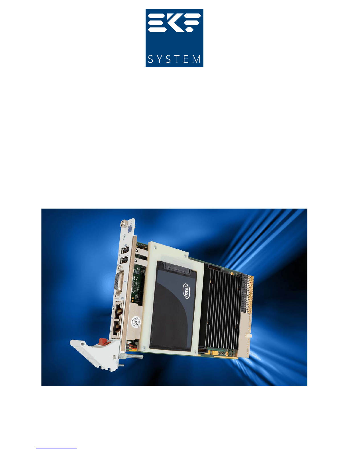
PC1-GROOVE
User Guide
PC1-GROOVE •
CompactPCI
® PlusIO
Core™ i7 Processor High Performance CPU Card
Suitable for Classic CompactPCI© and PICMG 2.30 CompactPCI® PlusIO Systems
Document No. 5713 • Edition 26 • 16 January 2015

User Guide • PC1-GROOVE • CoreTM i7 CompactPCI® CPU Board
Contents
About this Manual ........................................................... 4
Edition History......................................................... 4
Related Documents ..................................................... 5
Nomenclature ......................................................... 5
Trade Marks .......................................................... 5
Legal Disclaimer - Liability Exclusion ......................................... 5
Standards ............................................................ 6
PC1-GROOVE Features ........................................................ 7
Feature Summary ...................................................... 7
Block Diagram PC1-GROOVE ............................................. 11
Top View Component Assembly .......................................... 15
Strapping Headers ..................................................... 17
Connectors & Sockets .................................................. 17
Front Panel Elements ................................................... 17
Microprocessor ....................................................... 18
Thermal Considerations ................................................. 19
Main Memory ........................................................ 20
Graphics Subsystem ................................................... 21
LAN Subsystem ....................................................... 21
Serial ATA Interface (SATA) .............................................. 22
PCI Express Interface (PCIe) .............................................. 22
Universal Serial Bus (USB) ............................................... 23
Real-Time Clock....................................................... 23
LPC Super-I/O Interface ................................................. 23
SPI Flash ............................................................ 23
Reset............................................................... 24
Watchdog........................................................... 27
PG (Power Good) LED .................................................. 28
HD (Hard Disk Activity) LED .............................................. 28
GP (General Purpose) LED ............................................... 28
EB (Ethernet Backplane) LED ............................................. 29
Hot Swap Detection ................................................... 29
Power Supply Status (DEG#, FAL#) ........................................ 29
Mezzanine Side Board Options ........................................... 30
CompactPCI® PlusIO Option.............................................. 38
Installing and Replacing Components............................................ 45
Before You Begin...................................................... 45
Installing the Board .................................................... 46
Removing the Board ................................................... 47
EMC Recommendations................................................. 48
Installing or Replacing the Memory Module.................................. 49
Replacement of the Battery .............................................. 49
Technical Reference ......................................................... 50
Local PCI Devices ...................................................... 50
Local SMB Devices ..................................................... 51
Hardware Monitor LM87 ................................................ 51
GPIO Usage.......................................................... 52
GPIO Usage PCH................................................. 52
© EKF -2- ekf.com

User Guide • PC1-GROOVE • CoreTM i7 CompactPCI® CPU Board
Configuration Jumpers ................................................. 54
Configuration Switches PCI Express Link Width (DSW1) .................... 54
Loading UEFI BIOS Setup Defaults (P-GP)............................... 55
Manufacturer Mode Jumper (P-MFG) ................................. 55
Reset Jumper PCH RTC Core (P-RTC) .................................. 56
Connectors .......................................................... 57
Front Panel Connectors ............................................ 57
DisplayPort Monitor Connector J-DP ............................. 58
Video Monitor Connector J-VGA ............................... 61
USB Connectors ............................................ 62
Ethernet Connectors ........................................ 62
Internal Connectors .............................................. 63
Expansion Interface Header J-EXP............................... 63
High Speed Expansion Connector J-HSE .......................... 64
PCI Express Expansion Header J-PCIE............................. 65
SDVO2 Expansion Header J-SDVO2 ............................. 66
Front Panel Handle Microswitch Header P-FPH ..................... 67
PLD Programming Header P-ISP ................................ 68
Processor Debug Header XDP1................................. 68
CompactPCI J1............................................. 69
CompactPCI J2 (PlusIO) ...................................... 70
Appendix ................................................................. 72
Mechanical Drawings .................................................. 72
© EKF -3- ekf.com
User Guide • PC1-GROOVE • CoreTM i7 CompactPCI® CPU Board
About this Manual
This manual describes the technical aspects of the PC1-GROOVE, required for installation and system
integration. It is intended for the experienced user only.
Edition History
Ed.
Contents/Changes
Author Date
1 User Manual PC1-GROOVE, english, initial edition (Text #5713, File:
pc1_uge.wpd)
gn 2010-03-22
2 Added photos, added relational links jj 20 May 2010
3 Part # change USB connector jj 19 October 2010
4 Added to table Feature Summary: +3.3V V(I/O) option jj 5 November 2010
5 Changed default setting of switch DSW1 gn 2011-02-24
6 Changes due to Revision 1 gn 2011-03-31
7 Added description of the front panel handle integrated switch gn 2011-04-13
8 Added photos showing how to force system shutdown using the front
panel handle integrated switch
jj 12 May 2011
9 Added photos 'Small Systems' and 'Rugged Systems' jj 13 May 2011
10 BIOS usage of GP LED - document link added jj 18 May 2011
11 Added photos 'Hybrid Systems', added photos of mezzanine modules
and side cards, added photos of rear I/O module
jj 24 May 2011
12 Added factory settings of switch DSW1 for different side boards gn 2011-06-09
13 Added Power Requirements gn 2011-06-17
14 Added PCI-ID of JMB362 Rev. C Controller gn 2011-06-30
15 Table Feature Summary: Added Clock Rates of CPU Graphics Core jj 26 July 2011
16 Added photo PC1-C47 assembly jj 16 August 2011
17 Added photo C47-MSATA mezzanine module jj 22 August 2011
18 Added photos front view jj 25 August 2011
19 Added photos DisplayPort adapter, front panel handle micro switch jj 2 September 2011
20 Added photos DisplayPort cable adapter DVI & VGA jj 19 January 2012
21 Added photos low profile mezzanine modules exploded view jj 28 March 2012
22 Added MTBF value to table Feature Summary gn 2012-05-04
23 Added recommendation regarding DsiplayPort cable (pin 20 issue) jj 5 March 2013
24 Added information regarding selection of suitable intermediate PCB for
mezzanine connector SDVO2
jj 3 April 2013
25 Added photos PC1-PCS assemblyies jj 29 April 2013
26 Clarified resetting of UEFI BIOS settings to factory defaults gn 2015-01-16
© EKF -4- ekf.com

User Guide • PC1-GROOVE • CoreTM i7 CompactPCI® CPU Board
Related Documents
Related Information PC1-GROOVE
PC1-GROOVE Home www.ekf.com/p/pc1/pc1.html
PC1-GROOVE Ordering Information www.ekf.com/p/pc1/pc1_pi.pdf
Nomenclature
Signal names used herein with an attached '#' designate active low lines.
Trade Marks
Some terms used herein are property of their respective owners, e.g.
< Pentium, Celeron, Core™ i7, Arrandale, Ibex Peak-M, Calpella Platform, iAMT, Hanksville,
Hartwell: ® Intel
< CompactPCI : ® PICMG
< Windows XP, Windows 7, Windows 8: ® Microsoft
< EKF, ekf system: ® EKF
EKF does not claim this list to be complete.
Legal Disclaimer - Liability Exclusion
This manual has been edited as carefully as possible. We apologize for any potential mistake.
Information provided herein is designated exclusively to the proficient user (system integrator,
engineer). EKF can accept no responsibility for any damage caused by the use of this manual.
© EKF -5- ekf.com

User Guide • PC1-GROOVE • CoreTM i7 CompactPCI® CPU Board
Standards
Theme Document Title Origin
CompactFlash CF+ and CompactFlash Specification Revision 3.0 www.compactflash.org
CompactPCI CompactPCI Specification, PICMG 2.0 R3.0, Oct. 1,
1999
www.picmg.org
CompactPCI
PlusIO
CompactPCI PlusIO Specification, PICMG 2.30
R1.0, November 11, 2009
www.picmg.org
CompactPCI
Serial
Under developement www.picmg.org
DisplayPort VESA DisplayPort Standard Version 1.1
March 19, 2007
www.vesa.org
DVI Digital Visual Interface Rev. 1.0
Digital Display Working Group
www.ddwg.org
Ethernet IEEE Std 802.3, 2000 Edition standards.ieee.org
HD Audio High Definition Audio Specification Rev.1.0 www.intel.com/design/chipsets/hdaudio.htm
PCI Express PCI Express
®
Base Specification 1.1 www.pcisig.com
PCI Local Bus PCI 2.2/2.3/3.0 Standards PCI SIG www.pcisig.com
SATA Serial ATA 2.5/2.6 Specification www.sata-io.org
TPM Trusted Platform Module 1.2 https://www.trustedcomputinggroup.org
USB Universal Serial Bus Specification www.usb.org
© EKF -6- ekf.com

User Guide • PC1-GROOVE • CoreTM i7 CompactPCI® CPU Board
PC1-GROOVE Features
Feature Summary
Feature Summary PC1-GROOVE
Form Factor Single size CompactPCI® style Eurocard (160x100mm2), front panel width 4HP (20.3mm)
Processor Designed for Intel® Core™ i7 processors (codename Arrandale) with integrated graphics and
memory controller
< Maximum junction temperature of processor core 105°C (graphics core 100°C)
< Enhanced Intel® Speedstep® Technology
< Intel® Turbo Boost Technology
< Dual Core Multiprocessing
< Intel® Virtualization Technology (VT)
< Intel® 64 Architecture
< Refresh of 5th generation graphics core with 12 Execution Units
Available processors:
< Core™ i7-610E • 2.53GHz • 4MB L3 Cache • 35W TDP • 500/766MHz Graphics
< Core™ i7-620LE • 2.00GHz • 4MB L3 Cache • 25W TDP • 266/566MHz Graphics
< Core™ i7-660UE • 1.33GHz • 4MB L3 Cache • 18W TDP • 166/500MHz Graphics
< Core™ i7-620UE • 1.06GHz • 4MB L3 Cache • 18W TDP • 166/500MHz Graphics
Chipset Mobile Intel® 5 Series Chipset (Codename Ibex Peak):
QM57 Express Chipset Platform Controller Hub (PCH) with
< 8 PCI Express root ports at 2.5Gbps
< 6 x SATA 3Gbps
< Intel® Matrix Storage Technology (RAID 0, 1, 5, 10)
< High Definition Audio
< 14 x USB (2 EHCI controllers)
< Integrated GbE MAC
< iAMT
< Unified SPI Flash support
< 3 Digital Display Interfaces (DisplayPort, SDVO, HDMI)
< VGA interface with integrated 350MHz RAMDAC (resolution up to 2048x1536x24@75Hz)
Memory (RAM) < Maximum memory capacity of 8GB DDR3 up to 1066MHz
< 512Mb, 1Gb, 2Gb, [4Gb] technologies for x8 and x16 devices
< Channel 0 populated as directly soldered DDR3 devices (Memory Down)
< Channel 1 provided as 204-pin SODIMM socket to carry DDR3 module PC3-8500
< Dual channel symmetric – memory addresses interleaved for increased performance
(SODIMM module size must match Memory Down size)
< Intel® Flex Memory Technology (dual channel interleaved mode with unequal memory
population) - memory sizes maybe unequal in both the channels
< Dual channel asymmetric – memory sizes may differ, including no memory module
populated in the SODIMM socket (single-channel)
Video < Concurrently operation of two monitors with resolutions up to 2560x1536 pixel 16M
colours @60Hz refresh rate (DisplayPort), up to 1600 x 1200 pixel 16M colours @60Hz
(DVI-D on side boards like CCO-CONCERT)
< Dual screen capable (one display attached to the front panel DisplayPort connector, the
other to a digital display interface provided by a side board)
< Front panel option: D-Sub (female HD15) VGA connector available, replaces DisplayPort
connector
< Mezzanine option: Secondary DVI-D connector at mezzanine card front panel allows for
dual digital flat panel operation, suitable mezzanine modules e.g. CCH-MARIACHI, CCIRAP, CCJ-RHYTHM, CCO-CONCERT. Side boards providing a 2nd DisplayPort are projected
© EKF -7- ekf.com

User Guide • PC1-GROOVE • CoreTM i7 CompactPCI® CPU Board
Feature Summary PC1-GROOVE
USB < All ports over-current protected, data transfer rate of up to 480Mbps, conforming to
USB2.0
< 2 x USB type A connector (front panel)
< 4 x USB ports J2/P2 PlusIO
< 2 x USB ports via J-EXP expansion interface option (in use by several mezzanine side
boards)
< 4 x USB ports via J-HSE (e.g. C40-SCFA mezzanine storage module)
< Dual EHCI controllers provided by PCH QM57
Ethernet < Total of four 10/100/1000Mbps Gigabit Ethernet controllers, two accessible via RJ45 jacks
from the front panel, two fed to J2/P2 PlusIO
< ETH1 equipped with Intel® 82577LM PHY (codename Hanksville), serves also as AMT out
of band communication path (MAC provided by PCH QM57), Jumbo Frame support up to
4KB
< ETH2...4 equipped with Intel® 82574L GbE controller (codename Hartwell), connected to
local PCIe lanes, supports 9KB jumbo packets, TimeSync Offload compliant with 802.1as
specification
SATA < Total of eight 3Gbps SATA channels available
< Quad-channel Serial ATA 3Gbps available for J2/P2 PluIO (derived from PCH QM57)
< Intel® Matrix Storage Technology MST (Raid 1, 0, Matrix Raid)
< Secondary on-board PCIe to SATA controller JMB362, dual channel SATA RAID, available
via J-HSE expansion connector (plus 2 SATA channels in addition from PCH QM57)
< Additional PCIe to SATA controller on mezzanine side boards e.g. CCI-RAP,
CCK-MARIMBA, CCL-CAPELLA, CCO-CONCERT
PATA (IDE) < Option mezzanine module attached to J-HSE expansion connector
< C40-SCFA mezzanine module available with on-board SATA to PATA bridge and
CompactFlash socket
PCI Express < 12-Port PCIe Gen 2 switch provides 4 lanes to PCIe high-speed connector J-PCIE for CCJ-
RHYTHM and other mezzanine expansion cards, and 4 lanes to J2/P2 PlusIO interface
< Possible configurations on each interface 1 Link x 4 Lanes, 4 Links x 1 Lane
Mezzanine
Side Board
I/O
< J-EXP Legacy expansion interface connector LPC/USB/Audio (SIO, USB, HD Audio)
< J-HSE High-speed expansion interface connector (4 x SATA, 4 x USB)
< J-PCIE PCI Express 4-lane high-speed expansion connector
< J-SDVO2 additional digital graphics port high-speed expansion connector
< Suitable mezzanine companion side boards available, e.g.:
< CCI-RAP: 2 x PCI Express Mini Card sockets (WLAN, GSM, Wimax, Intel® Turbo
Memory), options secondary DVI-D, IEEE 1394 (FireWire), USB SSD, C20-SATA
mezzanine storage module (accommodates up to 2 SATA hard disk drives 2.5-inch
RAID capable)
< CCJ-RHYTHM: CompactPCI Express system slot controller function by on board 6-port
24-lane PCIe switch, options DVI-D, IEEE 1394 (FireWire)
< CCK-MARIMBA: PMC/XMC module carrier, option C20-SATA mezzanine storage
module
< CCL-CAPELLA: Up to 4 Gigabit Ethernet ports, options IEEE 1394 (FireWire), USB SSD,
C20-SATA mezzanine module
< CCO-CONCERT: Audio analog/digital, option secondary DVI-D
< C23-SATA: PCIe to 2 x SATA 1 x PATA controller
< C40-SCFA: SATA to PATA bridge & CompactFlash header, option USB SSD, 4HP
envelope maintained
< C42-SATA: 1.8-inch SATA Solid State Drive (SSD), 4HP envelope maintained
J2
CompactPCI®
PlusIO
< Suitable PlusIO backplanes available (e.g. Schroff)
< High-Speed UHM connector
< 4 x PCIe
< 4 x Serial ATA (SATA)
< 2 x Gbit Ethernet
< 4 x USB
© EKF -8- ekf.com

User Guide • PC1-GROOVE • CoreTM i7 CompactPCI® CPU Board
Feature Summary PC1-GROOVE
J1
CompactPCI®
< PCH QM57 integrated 32-bit PCI bridge, 33MHz 133MBps CompactPCI master
< Additional PCI arbiter in PLD for fully figured 8-slot CompactPCI backplane
< +5V V(I/O) default configuration (PCI pull-up resistors 1k - blue coding key on J1)
< +3.3V V(I/O) on request (PCI pull-up resistors 2.7k - yellow coding key on J1)
CompactPCI®
Express
< PC1-GROOVE can be configured as CompactPCI Express System Board (system slot
controller) by optionally available mezzanine expansion card CCJ-RHYTHM
< CPCIe 4-Link configuration (4-lanes each), for up to 4 CPCIe peripheral slots type 1 and/or
type 2 on a passive CPCIe backplane
< Suitable also for hybrid CPCI/CPCIe systems/backplanes (e.g. Schroff)
Platform
Management
< Option AMT 6.0 Intel® Active Management Technology (iAMT)
< ARM core based Manageability Engine (ME) in the PCH QM57
< Independent manageability firmware, stored in SPI Flash
Secure
Computing
< Option Trusted Platform Module TPM 1.2 according to Trusted Computing Group
specifications
< Available as discrete controller on several mezzanine boards e.g. CCH/CCI/CCJ
< Discrete crypto engine silicon brands Infineon or Atmel at users choice
BIOS < Phoenix BIOS with EKF enhancements for embedded systems
< SPI Flash memory 2 x 16/32/64 Mb
< Updates available from website ekf.com
Drivers
(All Major OS)
< Intel® graphics driver, Intel® embedded graphics driver
< Intel® networking driver
< Intel® Matrix Storage Manager software
< JMicron SATA driver
Thermal
Conditions
Environmental
Conditions
< Operating temperature: 0°C ... +70°C (extended temperature range on request)
< Storage temperature: -40°C ... +85°C, max. gradient 5°C/min
< Humidity 5% ... 95% RH non condensing
< Altitude -300m ... +3000m
< Shock 15g 0.33ms, 6g 6ms
< Vibration 1g 5-2000Hz
EC Regulations < EN55022, EN55024, EN60950-1 (UL60950-1/IEC60950-1)
< 2002/95/EC (RoHS)
MTBF 126 x 10
3
h (14 years) @ 50° C
Typical Power
Requirements
1)
Intel®
SpeedStep®
Frequency Modes
LFM: Low
Frequency Mode,
HFM: High
Frequency Mode
2)
Add per Ethernet
port 0.2/0.6A
(link only/active)
@1Gbps
Board
+3.3V +0.17V/-0.1V +5V +0.25V/-0.15V
MaxPower
LFM/HFM
1)
Win7 Idle
LFM/HFM
1)
MaxPower
LFM/HFM
1)
Win7 Idle
LFM/HFM
1)
PC1-62-GROOVE
6.1/6.4A
2)
2.9/2.9A
2)
2.3/5.8A 0.1/0.1A
S3: 250mA
S4: 80mA
S5: 80mA
S3: <10mA
S4: <10mA
S5: <10mA
© EKF -9- ekf.com
User Guide • PC1-GROOVE • CoreTM i7 CompactPCI® CPU Board
Performance
Rating
Measured with
PCMark2005
under Windows®
XP, 2 x 2GB
DDR3 1066
Board Processor CPU/MEM Score
PC1-6-GROOVE i7-610E TBD
PC1-4-GROOVE i7-620LE TBD
PC1-2-GROOVE i7-620UE TBD
Table items are subject to technical changes
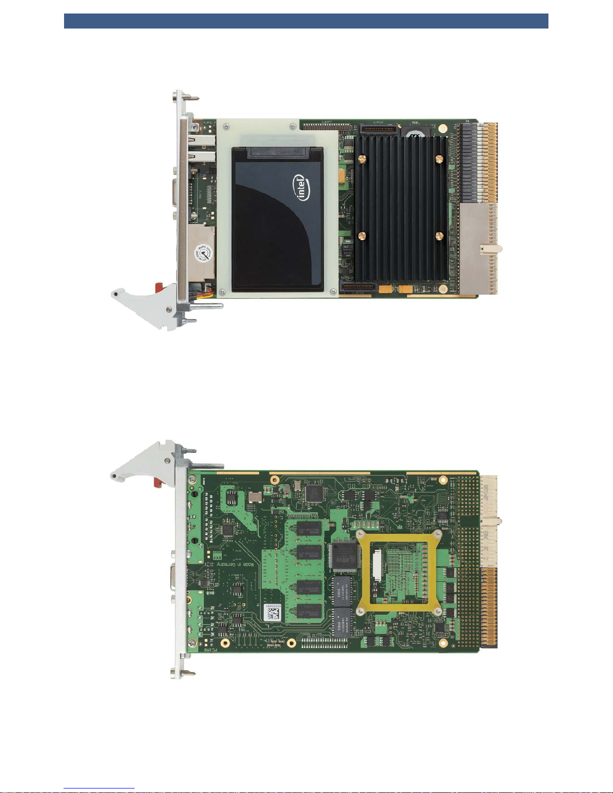
PC1-GROOVE (Option DisplayPort) and C41-CFast Module
© EKF -10- ekf.com
User Guide • PC1-GROOVE • CoreTM i7 CompactPCI® CPU Board
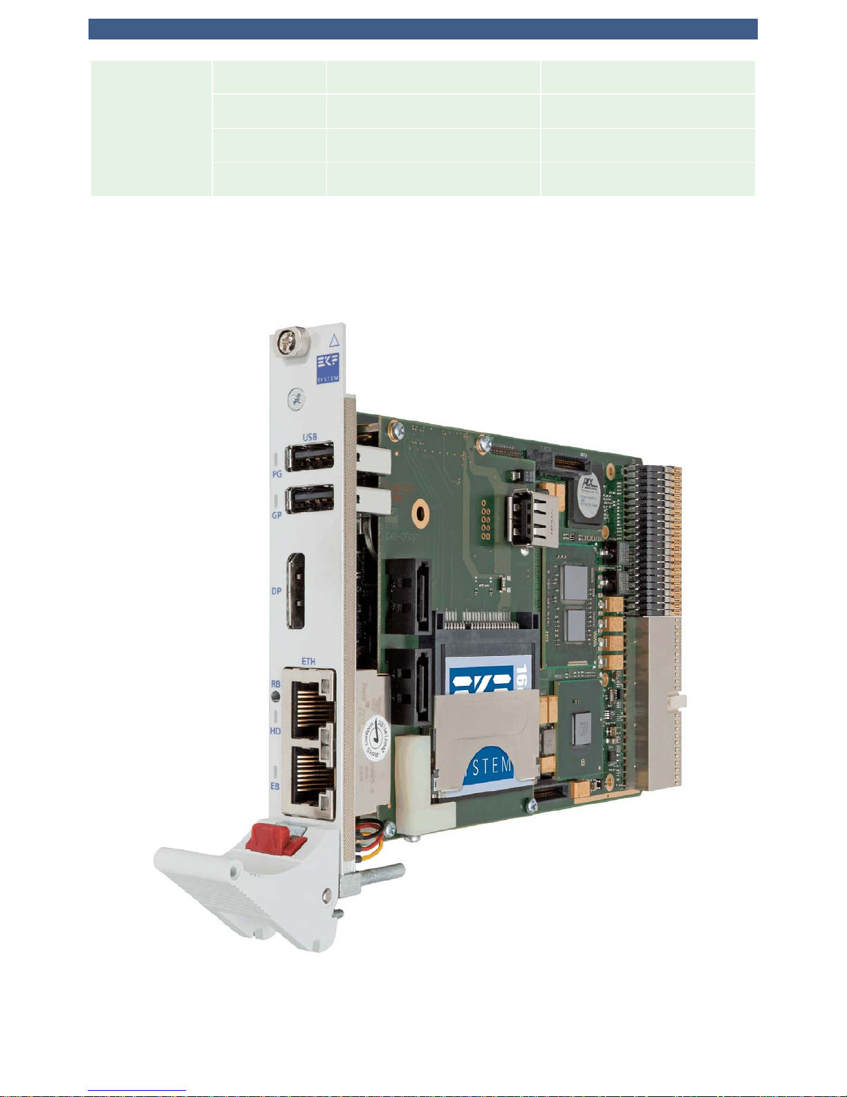
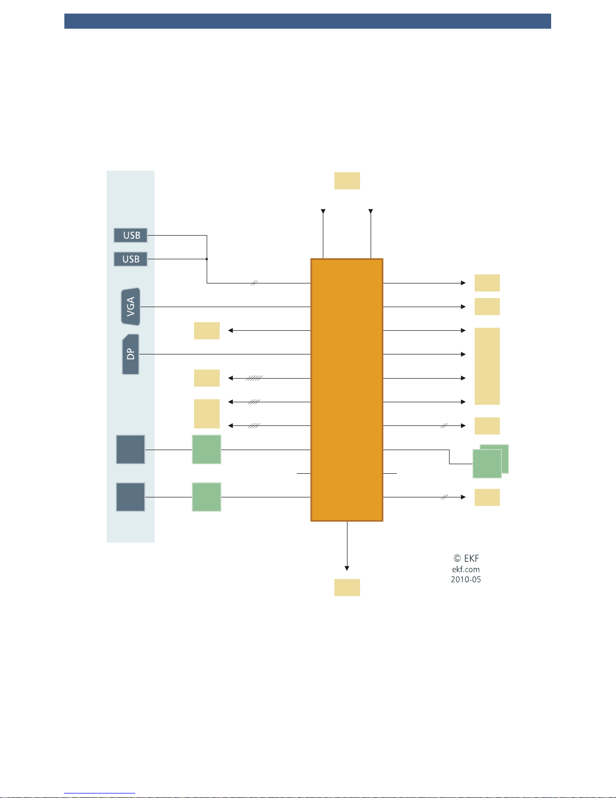
Block Diagram PC1-GROOVE
Simplified Block Diagram
PC1-GROOVE
Sheet 1 - CPU & RAM
DDR3 Soldered
DDR3 SO-DIMM
DDR3
800/1067
Dual Channel
i7-610E 2.53/3.2GHz SV
i7-620LE 2.0/2.8GHz LV
i7-660UE 1.33/2.4GHz ULV
i7-620UE 1.06/2.13GHz ULV
Intel® Low Power Platform Calpella+ECC
Arrandale+ECC
2 Cores - 4 Threads
DMI2
FDI
Low Power
Core™ i7
CPU
Sheet 3
PCIe
Switch
Sheet 2
PCH
PCIe 0.1 - 0.4
EKF
#1167
Document
© EKF -11- ekf.com
User Guide • PC1-GROOVE • CoreTM i7 CompactPCI® CPU Board
PCI
DDPC
GPIO
HD Audio
SMBUSUSB
Simplified Block Diagram
PC1-GROOVE
Sheet 2 - PCH
DMI2
FDI
CRT
PCH
QM57
IbexPeak-M
Hanksville
Front
Panel
I/O
GbE
1
DDPD
SDVO/DDPB
Front Panel
Stuffing Alternates -
either DisplayPort
or VGA
USB
82577
LM
PCIe 1.6
PCIe 1.5
SPI
Flash
SPI
Flash
SPI
LPC
GbE
2
82574
IT
Sheet 1
CPU
Sheet 4
J1
PCIe 1.8 PCIe 1.1 - 1.2
Sheet 3
J-DDP
Sheet 3
J-EXP
Sheet 3
J-SDVO2
Sheet 3
J-EXP J-HSE
Sheet 4
J2
PCIe 1.7
rfu
PCIe 1.3
PCIe 1.4
rfu
SATA
SATA
Sheet 3
J-HSE
Sheet 4
2 x 82574
Sheet 3
PCIe to SATA
USB
© EKF -12- ekf.com
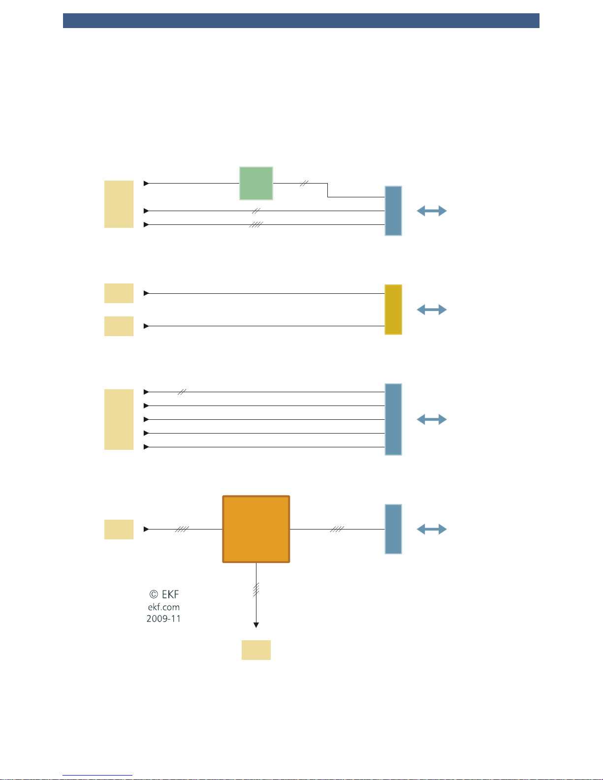
User Guide • PC1-GROOVE • CoreTM i7 CompactPCI® CPU Board
SATA
SATA
SDVO
USB
GPIO
HD Audio
LPC
J-PCIE
Opt. Mezz.
Exp. Board
PCIe
Gen2
Switch
PCIe 3.1 - 3.4
PCIe 2.1 - 2.4PCIe 0.1 - 0.4
J-EXP
PEX 8614
12 x 12
JMB362
SMBUS
USB
J-HSE
PCIe
SATA
PCIe 1.5
Simplified Block Diagram
PC1-GROOVE
Sheet 3 - Mezzanine Connectors
DDPC
Hanksville
Sheet 2
PCH
Sheet 1
CPU
Sheet 4
J2
Sheet 2
PCH
Sheet 2
PCH
Sheet 2
PCH
J-SDVO2
© EKF -13- ekf.com
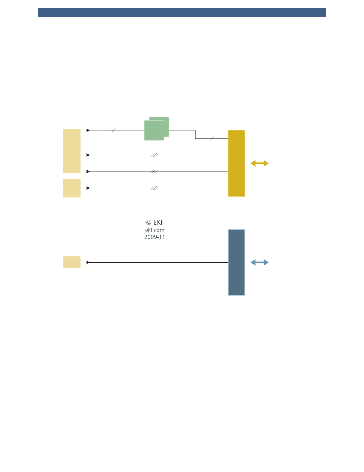
User Guide • PC1-GROOVE • CoreTM i7 CompactPCI® CPU Board
PCIe 3.1 - 3.4
USB
PCI
GbE
CPCI
J1
SATA
J2
PICMG 2.30
PlusIO RIO
or
CPCI Serial
Backplane
CompactPCI
Backplane
32-Bit
82574
IT
82574
IT
PCIe 1.1 - 1.2
Simplified Block Diagram
PC1-GROOVE
Sheet 4 - Backplane Connectors
PlusIO
Hartwell
Hanksville
Sheet 2
PCH
Sheet 3
PCIe
Switch
Sheet 2
PCH
© EKF -14- ekf.com
User Guide • PC1-GROOVE • CoreTM i7 CompactPCI® CPU Board
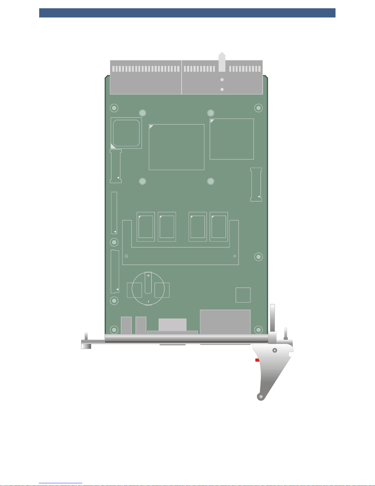
Top View Component Assembly
J-HSE
J-PCIE
J-EXP
SODIMM DDR3
J-SDVO2
Intel®
Core™ i7
SV/LV/ULV
Memory
Down
Dual
GbE
USB
USB
VGA
DP
© EKF
ekf.com
J1
J2
UHM
PC1-GROOVE • CompactPCI® PlusIO • © EKF • ekf.com
© EKF -15- ekf.com
User Guide • PC1-GROOVE • CoreTM i7 CompactPCI® CPU Board
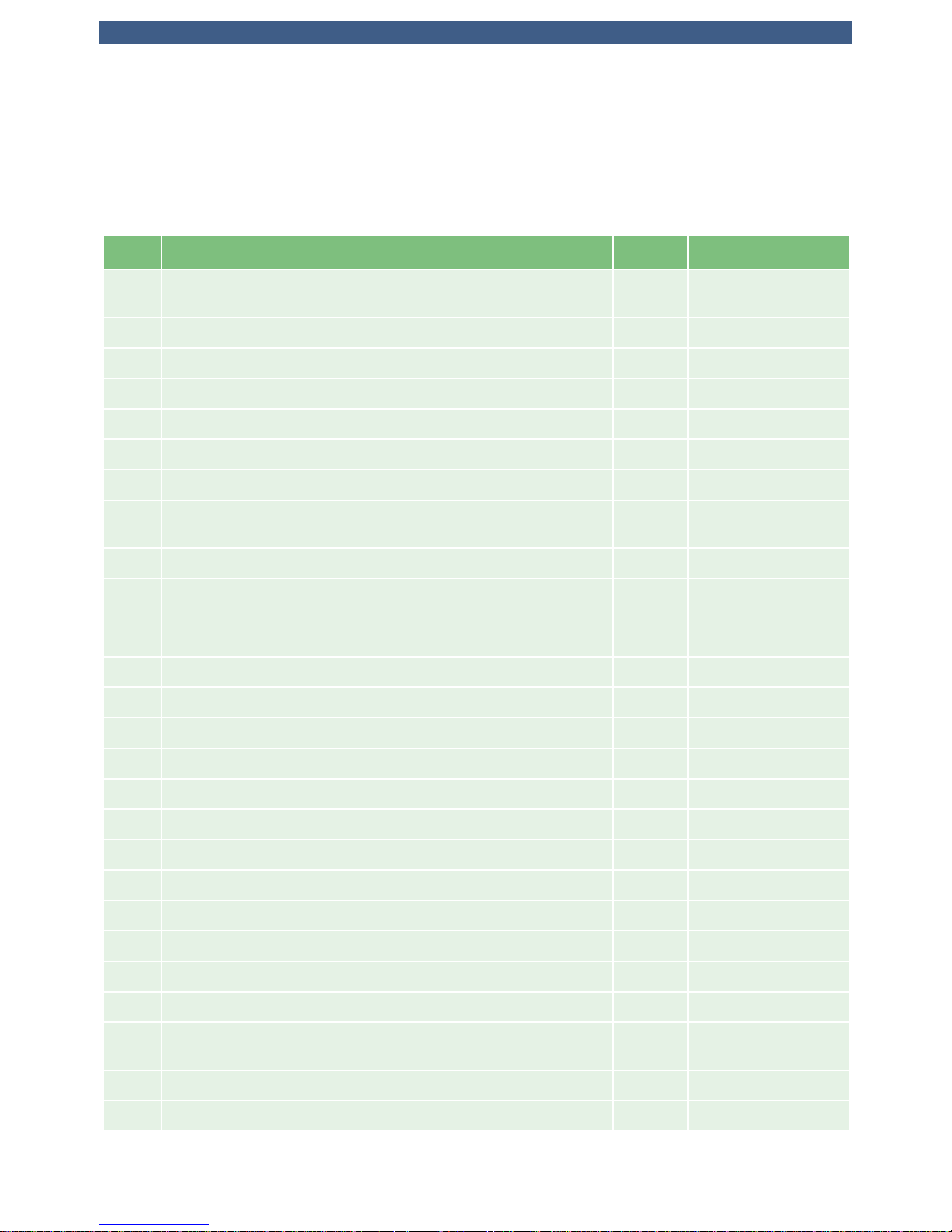
PC1-GROOVE Top View
PC1-GROOVE Bottom View
© EKF -16- ekf.com

User Guide • PC1-GROOVE • CoreTM i7 CompactPCI® CPU Board
Strapping Headers
DSW1 Switches to configurate PCIe link width
P-FPH Jumper to generate Power Button Events (Front Panel Handle Switch)
P-ISP PLD Programming Connector, not stuffed
P-GP Jumper to reset UEFI BIOS Setup to EKF Factory Defaults
P-MFG Jumper to enter Manufacturing Mode, not stuffed
P-RTC Jumper to reset RTC Core of PCH, not stuffed
Connectors & Sockets
J1/J2
CompactPCI Bus 32-bit, 33MHz, PlusIO
J-EXPT
J-EXPB
1)
Expansion Interface Connector (LPC Interface (Super-I/O, FWH), USB
Interfaces, HD Audio Interface, SMBus), available either from top (T)
or bottom (B) of the board
J-HSE High Speed Expansion Connector (4 x SATA, 4 x USB), Interface to
CompactFlash Carrier C40-SCFA and side boards
J-PCIE PCI Express Expansion Interface Connector
J-SDVO2 Digital Display Interface Connector
SODM1 204-pin DDR3 Memory Module SDRAM PC3-8500 Socket
XDP1 CPU Debug Port
1)
Stuffed on customers request only
Front Panel Elements
Ethernet
(ETH1/2)
Dual 1000Base-TX/100Base-TX/10Base-T, RJ-45 Receptacles with
integrated indicator LEDs
Graphics
(DisplayPort)
DisplayPort Receptacle. Alternately available with VGA Connector.
USB1/2 Universal Serial Bus 2.0 self powered root hub, type A receptacle
EB LED indicating PlusIO Ethernet activity
GP General Purpose LED
HD LED indicating any activity on SATA ports
PG LED indicating Power Good/Board Healthy
RB System Reset Button
© EKF -17- ekf.com

User Guide • PC1-GROOVE • CoreTM i7 CompactPCI® CPU Board
Microprocessor
The PC1-GROOVE is designed for use with Intel® CoreTM i7 processors (code name Arrandale). These
processors integrate the graphics and memory controller within one chip that up to now were located
in an external part of the chipset (GMCH). As a result the platform core is reduced from the known
three chip solution (CPU, GMCH, ICH) to only two devices (CPU, PCH).
The CoreTM i7 family includes beside the Standard-Voltage (SV) also several Ultra Low-Voltage (ULV)
and Low-Voltage (LV) processors as listed below. The processors are housed in a Micro FC-BGA
package for direct soldering to the PCB, i.e. the chip cannot be removed or changed by the user.
The processors supported by the PC1-GROOVE are running at core clock speeds up to 2.53GHz. Due
to Enhanced Intel® SpeedStep® and Intel® Turbo Boost Technology each core can decrease or
increase its nominal operating frequency. The internal CoreTM i7 processor speed is achieved by
multiplying the host base frequency of 133MHz by a variable value. The multiplier is chosen
depending on the power states of the processor cores/graphics engine, the currently required
performance, and the actual core temperature.
Power is applied across the CompactPCI connectors J1 (3.3V, 5V). The processor core voltage is
generated by a switched voltage regulator, sourced from the 5V plane. The processor signals its
required core voltage by 7 dedicated pins according to Intels IMVP-6.5 voltage regulator specification.
Processors Supported
Processor Number
of Cores
Speed
min/max
[GHz]
L3
Cache
[MB]
TDP
[W]
Die Temp
[°C]
CPU ID Stepping sSpec
ULV Core i7-620UE 2 0.67/1.06 4 18 0-105 20652h C-2 SLBPA
ULV Core i7-660UE 2 0.67/1.33 4 18 0-105 20655h K-0 SLBWV
LV Core i7-620LE 2 1.20/2.00 4 25 0-105 20652h C-2 SLBP9
SV Core i7-610E 2 1.20/2.53 4 35 0-105 20652h C-2 SLBRZ
© EKF -18- ekf.com

User Guide • PC1-GROOVE • CoreTM i7 CompactPCI® CPU Board
Thermal Considerations
In order to avoid malfunctioning of the PC1-GROOVE, take care of appropriate cooling of the
processor and system, e.g. by a cooling fan suitable to the maximum power consumption of the CPU
chip actually in use. The processor contains digital thermal sensors (DTS) that are readable via special
CPU registers. DTS allows to get the temperatures of each CPU core separately.
Two further temperature sensors located in the system hardware monitor LM87 allows for acquisition
of the boards surface temperature and the thermal state of the onboard system memory channel.
Beside this the LM87 also monitors most of the supply voltages. A suitable software on Microsoft
Windows® systems to display both, the temperatures as well as the supply voltages, is Speedfan,
which can be downloaded from the web. After installation, both temperatures and voltages can be
observed permanently from the Windows® taskbar.
The PC1-GROOVE is equipped with a passive heatsink. Its height takes into account the 4HP limitation
in mounting space of a CompactPCI board. In addition, a forced vertical airflow through the system
enclosure (e.g. bottom mount fan unit) is strongly recommended (>20m3/h or 2m/s (400LFM) around
the CPU slot). Be sure to thoroughly discuss your actual cooling needs with EKF. Generally, the faster
the CPU speed the higher its power consumption. For higher ambient temperatures, consider
increasing the forced airflow to 3m/s (600LFM) or more.
The table showing the supported processors above give also the maximum power consumption (TDP
= Thermal Design Power) of a particular processor. Fortunately, the power consumption is by far
lower when executing typical Windows® or Linux tasks. The heat dissipation increases when e.g.
rendering software like the Acrobat Distiller is executed.
The CoreTM i7 processors support Intel's Enhanced SpeedStep® technology. This enables dynamic
switching between multiple core voltages and frequencies depending on core temperature and
currently required performance. The processors are able to reduce their core speed and core voltage
in multiple steps down to 1200MHz (667MHz for ULV processors). This leads to an obvious reduction
of power consumption resulting in less heating. This mode of lowering the processor core
temperature is called TM2 (TM=Thermal Monitor).
Another way to reduce power consumption is to modulate the processor clock. This mode (TM1) is
achieved by actuating the 'Stop Clock' input of the CPU. A throttling of 50% e.g. means a duty cycle
of 50% on the stop clock input. However, while saving considerable power consumption, the data
throughput of the processor is also reduced. The processor works at full speed until the core
temperature reaches a critical value. Then the processor is throttled by 50%. As soon as the high
temperature situation disappears the throttling will be disabled and the processors runs at full speed
again.
These features are controllable by BIOS menu entries. By default the BIOS of the PC1-GROOVE enables
mode TM2 which is the most efficient.
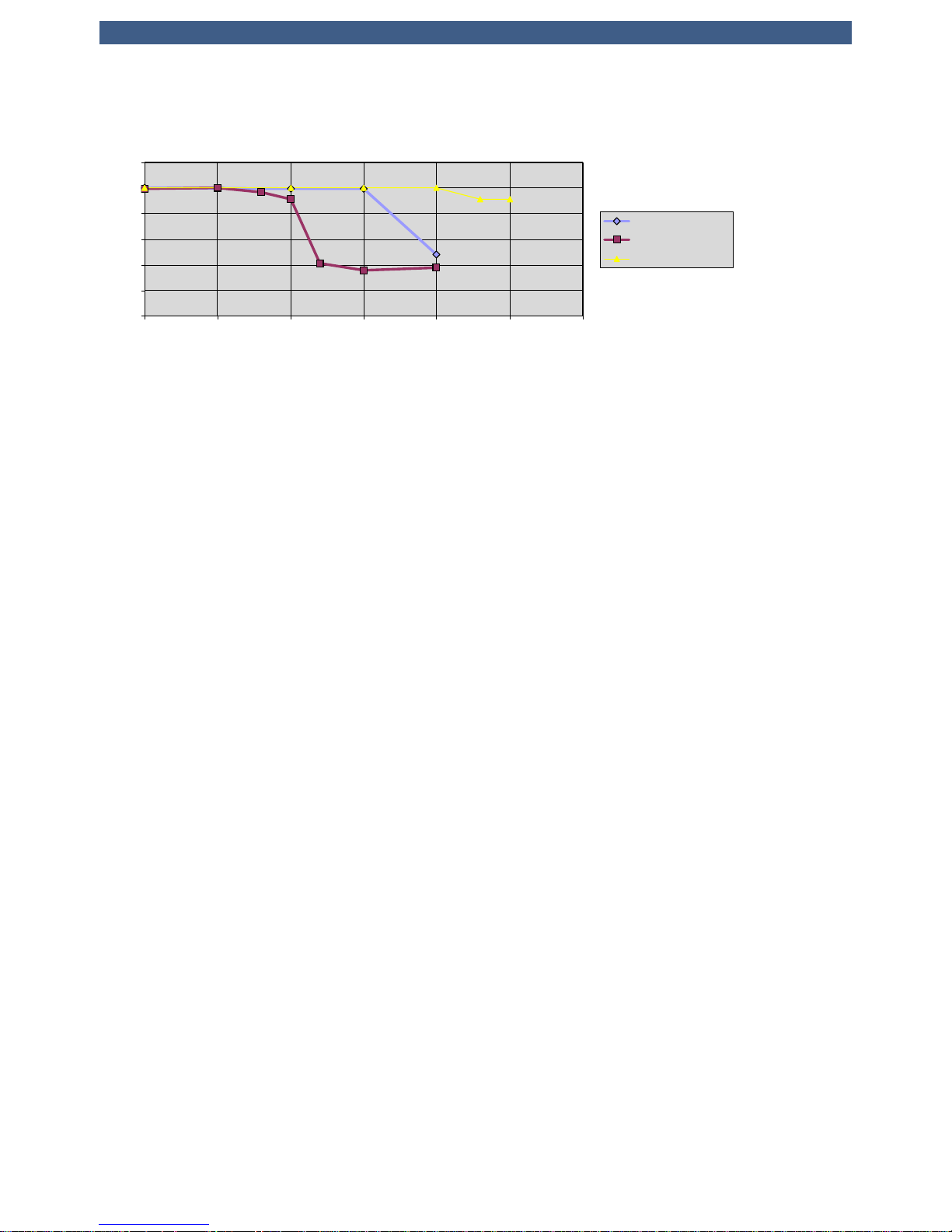
The following diagram shows the performance derating with increasing temperature for an i7-610E
processor running at its maximum (2.53GHz) and minimum (1.20GHz) frequency as well as an i7660UE ULV processor at 1.33GHz.
© EKF -19- ekf.com
User Guide • PC1-GROOVE • CoreTM i7 CompactPCI® CPU Board
Main Memory
The PC1-GROOVE features two channels of DDR3 SDRAMs. One channel is realized with 8 memory
devices soldered to the board (Memory Down) and delivers a capacity of up to 4GB with a clock
frequency of 1066MHz (PC3-8500).
The 2nd channel provides a socket for installing a 204-pin SODIMM module thus allowing a simple
expansion of system memory (max. module height = 1.25 inch). Supported are unbuffered DDR3
SODIMMs (VCC=1.5V) without ECC featuring on-die termination (ODT), according the PC3-6400 or
PC3-8500 specification. Minimum module size is 512MB; maximum module size is 4GB.
It is recommended to add a SODIMM module with same size as the Memory Down to get best
performance (some of the system memory is dedicated to the graphics controller). This typically results
in a size of 2x1GB of memory which is recommended to run the operating systems Windows® XP,
Windows® Vista or Windows® 7.
The memory controller supports symmetric and asymmetric memory organization. The maximum
memory performance can be obtained by using the symmetric mode. When in this mode, the memory
controller accesses the memory channels in an interleaved way. Since Core
TM
i7 processors support
Intels Flex Memory Technology, interleaved operation isn't limited to systems using memory channels
of equal capacity. In the case of unequal memory population the smaller memory channel dictates the
address space of the interleaved accessible memory region. The remainder of the memory is then
accessed in non-interleaved mode.
In asymmetric mode the memory always will be accessed in a non-interleaved manner with the
drawback of less bandwidth. The only meaningful application of asymmetric mode is the special case
when only one memory channel is populated (i.e. the SODIMM socket may be left empty).
The contents of the SPD EEPROM on the SO-DIMM is used by the BIOS at POST (Power-on Self Test)
to get any necessary timing parameters to program the memory controller within the chipset.
Performan ce Der at ing
Core®i7-610E/-660UE
Airflow=2.5m/s
0
20
40
60
80
100
120
60 65 70 75 80 85 90
Temp °C
i7-610E, 1. 2G Hz
i7-610E, 2. 53G Hz
i7-660UE, 1.33GHz
© EKF -20- ekf.com

User Guide • PC1-GROOVE • CoreTM i7 CompactPCI® CPU Board
Graphics Subsystem
The graphics subsystem is part of the Intel CoreTM i7 processor and the PCH QM57. While the graphics
controller is located within the CoreTM i7 processor, the different interfaces like DisplayPort, SDVO and
VGA are moved to the PCH. The PC1-GROOVE offers one DisplayPort interface in the front panel.
Adapters to convert DisplayPort to any other popular interface standard are available.
A 2nd DisplayPort and an SDVO port is fed to the on-board connector J-SDVO2. Currently expansion
boards like CCH-MARIACHI feature the display transmitter to provide a DVI channel via a pure digital
DVI-D connector. Future EKF expansion boards will feature also the possibility to gain access to a 2
nd
DisplayPort interface.
As an option, the PC1-GROOVE can be equipped with an ordinary HD D-Sub 15-lead connector (VGA
style). This connector is suitable for analog signals only. Nevertheless also flat-panel displays can be
attached to the D-Sub connector but with minor reduced image quality.
Independent from the video connector actually in use, DisplayPort, DVI or VGA, the VESA DDC
standard is supported. This allows to read out important parameters, e.g. the maximum allowable
resolution, from the attached monitor. If stuffed, DDC Power (+5V) is delivered to the legacy VGA
connector. A resettable fuse is used to protect the board from an external short-circuit condition
(0.5A).
Graphics drivers for the CoreTM i7 can be downloaded from the Intel web site.
LAN Subsystem
The Ethernet LAN subsystem is composed of four Gigabit Ethernet ports: One Intel 82577LM Physical
Layer Transceiver (PHY) using the PCH QM57 internal MAC and three Intel 82574L Gigabit Ethernet
Controllers. These devices provide also legacy 10Base-T and 100Base-TX connectivity. Two of the
Ethernet ports are fed to two RJ45 jacks located in the front panel, the others are attached to the
PlusIO interface on J2/P2. Each port includes the following features:
• One PCI Express lane per Ethernet port (250MB/s)
• 1000Base-Tx (Gigabit Ethernet), 100Base-TX (Fast Ethernet) and 10Base-T (Classic Ethernet)
capability.
• Half- or full-duplex operation.
• IEEE 802.3u, 802.3ab Auto-Negotiation for the fastest available connection.
• Jumperless configuration (complete software-configurable).
Two bicoloured LEDs integrated into the dedicated RJ-45 connector in the front panel are used to
signal the LAN link, the LAN connection speed and activity status. A further bicoloured LED in front
panel labelled EB displays the state of the PlusIO network ports.
Each device is connected by a single PCI Express lane to the PCH. Their MAC addresses (unique
hardware number) are stored in dedicated FLASH/EEPROM components. The Intel Ethernet software
and drivers for the 82577 and 82574 is available from Intel's World Wide Web site for download.
When managing the board by Intel Active Management Technology (iAMT), the dedicated network
port to do so is accessible by the RJ45 connector GbE1 (the upper port within the front panel).
© EKF -21- ekf.com

User Guide • PC1-GROOVE • CoreTM i7 CompactPCI® CPU Board
Serial ATA Interface (SATA)
The PC1-GROOVE provides eight serial ATA (SATA) ports each capable of transferring 3Gbps
(300MByte/s). Four of the six ports integrated within the PCH are routed to the CompactPCI PlusIO
interface (J2/P2 connector). The remainder SATA channels of the PCH and two further ports coming
from an additional controller (JMicron JMB362) are fed to the high speed expansion connector J-HSE.
This connector allows the installation of local expansion boards like C40-SCFA to attach the popular
CompactFlash cards.
A LED named HD located in the front panel, signals disk activity status of the SATA devices.
Available for download from Intel's and JMicron's web sites are drivers for popular operating systems,
e.g. Windows® XP, Windows® Vista, Windows® 7 and Linux.
PCI Express Interface (PCIe)
On PC1-GROOVE four PCI Express lanes, originating from the CoreTM i7 processor, are building one
upstream link to a PCI Express switch. The output ports (downstream ports) of the PCIe switch are
connected to the CompactPCI PlusIO connector J2/P2 (four lanes) and to the local PCIe expansion
interface connector J-PCIE (four lanes).
Two small DIP switches (DSW1) located on the backside of the board are used to configure different
lane widths to each of both downstream interfaces. Possible settings are
• A single link x 4 lanes to J2/P2 and a single link x 4 lanes to J-PCIE
• Four links x 1 lane to J2/P2 and a single link x 4 lanes to J-PCIE
• Four links x 1 lane to J2/P2 and four links x 1 lane to J-PCIE
See section “Configuration Switches PCI Express Link Width (DSW1)” for details.
While the link speed on the upstream side of the switch is restricted to 2.5GT/s due to limitations of
the PCH QM57, the downstream ports may support also PCIe Gen 2 speed (5GT/s).
© EKF -22- ekf.com

User Guide • PC1-GROOVE • CoreTM i7 CompactPCI® CPU Board
Universal Serial Bus (USB)
The PC1-GROOVE is provided with twelve USB ports, all of them are USB 2.0 capable. Two USB
interfaces are routed to front panel connectors, two ports are feed to the expansion board interface
connectors J-EXP, four to the high speed expansion connector J-HSE, and four ports are available
across the J2/P2 connector for PlusIO.
The front panel USB connectors can source up to 0.5A/5V each, over-current protected by two
electronic switches. Protection for the USB ports on the expansion interfaces and on the PlusIO
connector is located on expansion boards like CCH-MARIACHI and the boards on the CompactPCI
Serial backplane respective. The two USB EHCI controllers handling the USB ports are integrated into
the PCH.
Real-Time Clock
The PC1-GROOVE has a time-of-day clock and 100-year calendar, integrated into the PCH. A battery
on the board keeps the clock current when the computer is turned off. The PC1 uses a BR2032 lithium
battery soldered in the board, giving an autonomy of more than 5 years. Under normal conditions,
replacement should be superfluous during lifetime of the board.
In applications were the use of a battery is not permitted, a SuperCap can be stuffed instead of the
battery.
LPC Super-I/O Interface
In a modern system, legacy ports like PS/2 keyboard/mouse, COM1/2 and LPT have been replaced by
USB and Ethernet connectivity. Hence, the PC1-GROOVE is virtually provided with all necessary I/O
ports. However, for compatibility purposes the PC1 is equipped with the interface connector J-EXP to
the local LPC bus (LPC = Low Pin Count interface standard), which is a serialized ISA bus replacement.
EKF offers multiple expansion boards to the PC1-GROOVE, featuring all classic Super-I/O functionality,
for example the CCH-MARIACHI. Access to the connectors PS/2 (mouse, keyboard), COM, USB and
audio in/out is given directly from the front panel. The CCH-MARIACHI connects to the PC1-GROOVE
across the connectors P-EXPT or P-EXPB. Usually the CCH is attached to the top of the PC1-GROOVE.
Nevertheless bottom side mounting is possible on customers request.
SPI Flash
The BIOS is stored in two flash devices with Serial Peripheral Interface (SPI). 8MByte of BIOS code,
AMT firmware and user data may be stored nonvolatile in these SPI flashs (up to 16MByte of flash
space is available on request).
The SPI flash contents can be reprogrammed (if suitable) by a DOS or Linux based tool. This program
and the latest PC1-GROOVE BIOS binary are available from the EKF website. Read carefully the
enclosed instructions. If the programming procedure fails e.g. caused by a power interruption, the
PC1-GROOVE may no more be operable. In this case you would possibly have to send in the board,
because the flash devices are directly soldered to the PCB and cannot be changed by the user.
© EKF -23- ekf.com

User Guide • PC1-GROOVE • CoreTM i7 CompactPCI® CPU Board
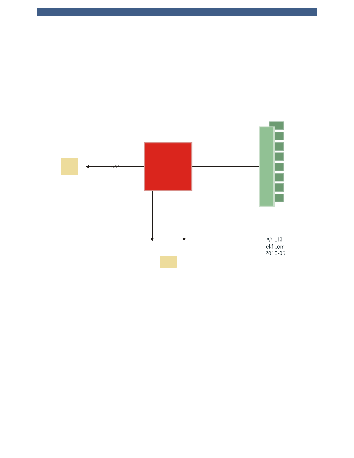
Reset
The PC1-GROOVE is provided with several supervisor circuits to monitor supply rails like the CPU core
voltage, 1.5V, 3.3V or 5V. This circuitry is responsible also to generate a clean power-on reset signal.
To force a manual board reset the PC1-GROOVE offers a small tactile switch within the front panel.
This push-button is indent mounted and requires a tool, e.g. a pen to be pressed, preventing from
being inadvertently activated.
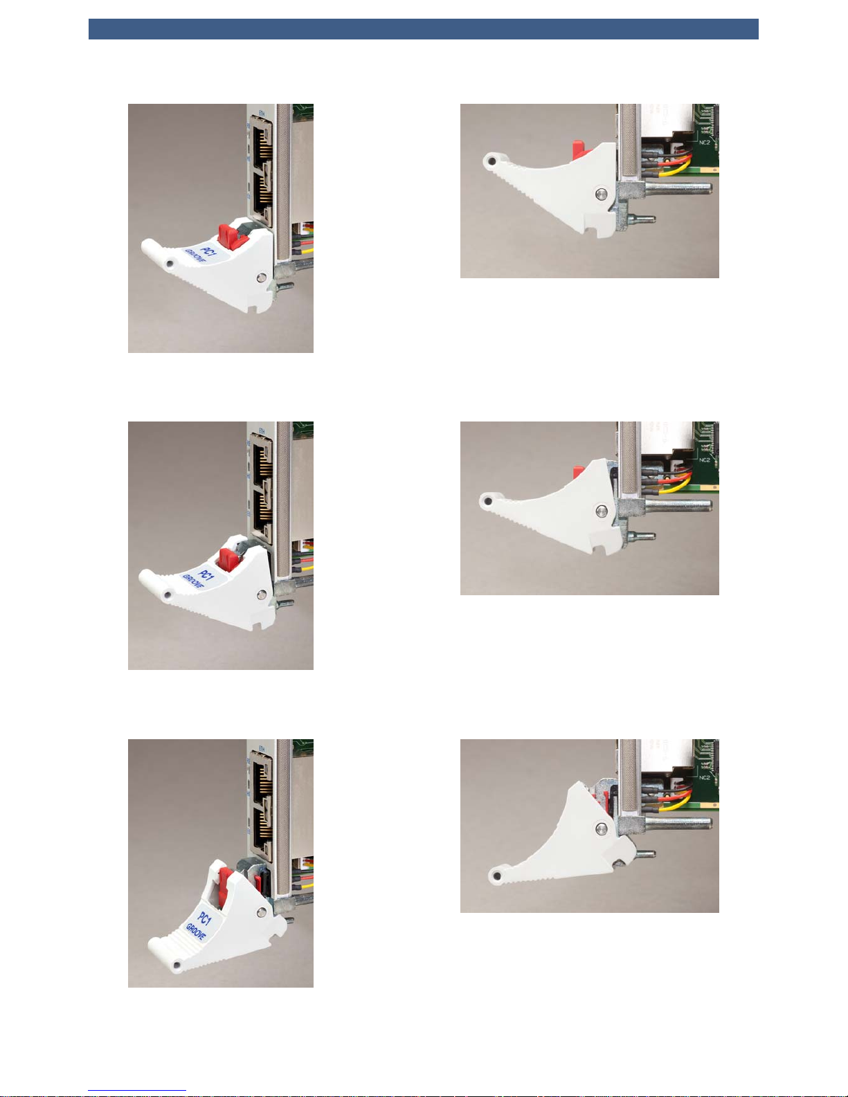
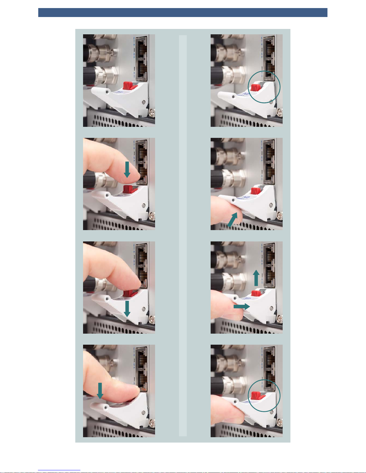
The ejector within the front panel contains a micro switch that is used to generate a power button
event. This is done by pushing the red button of the ejector until the handle unlocks without ejecting
the board. Immediately after that push up the ejector back to its original position (the red button
jumps up as well). Animated GIF: www.ekf.com/c/ccpu/img/reset_400.gif
NOTE: To prevent the board to cause a power button override, the handle should be closed
immediately after unlocking the front panel handle. A power button override is triggered by opening
the front panel handle for at least 4 seconds. It results in bringing the board to power state S5. In
case of entering this state, unlock and lock the front panel handle a 2nd time to reenter normal power
state S0 again. See also section 'PG (Power Good) LED' to see how the PC1-GROOVE indicates the
different power states.
WARNING: The PC1-GROOVE will enter the power state S5 if the front panel handle is not closed
properly when the system powers up. An open handle is signalled by a yellow blinking ‘PG LED’.
The manual reset push-button and the power button functionality of the front panel handle could be
passivated by BIOS settings.
An alternative (and recommended) way to generate a system reset is to activate the signal PRST#
located on CompactPCI connector J2 pin C17. Pulling this signal to GND will have the same effect as
to push the tactile reset switch.
The healthy state of the PC1-GROOVE is indicated by the LED PG (Power Good) located in the front
panel. This bicoloured LED signals different states of the board (see section below). As soon as this
LED begins to shine green all power voltages are within their specifications and the reset signal has
been deasserted.
© EKF -24- ekf.com
User Guide • PC1-GROOVE • CoreTM i7 CompactPCI® CPU Board
© EKF -25- ekf.com
User Guide • PC1-GROOVE • CoreTM i7 CompactPCI® CPU Board
© EKF • ekf.com
1
2
3
4
5
6
7
8
<4s
© EKF -26- ekf.com
 Loading...