

EKF HemataStat II Operator's Manual

HemataStat II
™
Centrifuge
Operator’s Manual
Separation Technology, Inc.
An EKF Diagnostics Company
570 Monroe Road, Suite 1008
Sanford, FL 32771
800-777-6668, 407-788-3677
www.separationtechnology.com

TABLE OF CONTENTS
SECTION 1 DESCRIPTION AND INTENDED USE ........................... 2
SECTION 2 INSTALLATION .............................................................. 2
2.1 Unpacking
2.2 Power Supply
2.3 Optional Rechargeable Battery Pack
SECTION 3 SETUP PROCEDURE..................................................... 5
3.1 Display Options
3.2 Setup Menu and Procedure
SECTION 4 OPERATING INSTRUCTIONS ....................................... 8
4.1 Start Up
4.2 Rotor Loading and Balancing
4.3 Tube Preparation
4.4 Tube Centrifugation
4.5 Reading a Capillary Tube
4.6 Hematocrit Determination Reminders
SECTION 5 QUALITY CONTROL AND ASSURANCE ................... 15
5.1 Use of Hematology Reference Control
5.2 Calibration
5.3 Spin Time/RPM Tests
SECTION 6 MAINTENANCE ............................................................ 16
6.1 Cleaning
6.2 Tube Holders
6.3 Inspections
6.4 Service
SECTION 7 TROUBLESHOOTING .................................................. 18
SECTION 8 ACCESSORIES, CONTROLS AND SUPPLIES ........... 19
SECTION 9 WARRANTY ................................................................. 20
SECTION 10 SPECIFICATIONS ........................................................ 21

1
SECTION 1
DESCRIPTION AND INTENDED USE
The Separation Technology, Inc. (STI) HemataStat II
™
Microhematocrit System is a
small, lightweight centrifuge which provides a rapid and accurate microhematocrit
determination using capillary or venous blood samples. The HemataStat II is not
intended for use with materials other than blood.
The rotor will accommodate up to six standard 75mm capillary tubes. The device will
achieve specimen separation in only one minute.
For convenience and ease of use, the HemataStat II system also includes a built-in
automatic tube reader and a LCD that displays messages to gui de the operator throughout
the testing procedure and then displays the test results.
An optional rechargeable battery pack is available to permit operation in remote locations
where alternating current is not available. The HemataStat II has a CLIA '88 W AIVED status.
SECTION 2
INSTALLATION
2.1 UNPACKING
The HemataStat II shipping box contains:
• Centrifuge
• Package of ten disposable tube holders
• Power supply
• Operator’s manual
• Laminated quick reference procedure guide
• Laminated tube placement guide
• Instruction video
Read the operator’s manual thoroughly before operating this system.
VIEWING THE INSTRUCTION VIDEO BEFORE PROCEEDING WILL BE HELPFUL
FOR PROPER OPERATOR TRAINING.
Place the centrifuge on a convenient, level work surface along with the other items
contained in the box.

2
2.2 POWER SUPPLY
Use ONLY the power supply packaged with the HemataStat II. Verify that the
ON/OFF switch located on the top of the centrifuge is in the OFF "
" position.
Always plug the power supply into the rear of the device first
and then plug the threeprong end into an electrical outlet. Press the ON/OFF switch to the ON " ʘ" position.
The lid will automatically open and the LCD will display the main menu.
2.3 OPTIONAL RECHARGEABLE BATTERY PACK
A. INSTALLATION
For complete portability, the HemataStat II will operate on a rechargeable
battery pack, which can be ordered as an option. The battery pack will need to
be installed in the device as described below and fully charged before normal
operation.
1. Make certain the lid is closed and locked and the centrifuge is unplugged
from the electrical outlet. Lock the lid by firmly pressing down on the lid
tab.
2. Place the device upside down on a smooth, flat surface and on a cloth or
other protective material to prevent scratching the lid.
3. Locate the battery pack cover. Using a small head Phillips screwdriver,
remove the screws holding the battery pack cover in place. Retain the
screws. Remove the battery pack cover.
4. Connect the battery pack plug into the connector loc ate d in side th e ba tter y
pack cavity. Put the connector inside the hole of the housing with the
connector release tab facing up. Position the battery pack inside the
compartment. Lay the cable along side the batter y pa ck t o av oid cri mpin g.
5. Replace the battery pack cover and secure with the screws provided.
6. Plug in the HemataStat II and fully charge the battery pack.
B. CHARGING THE BAT TERY PACK
The battery pack is always charging whenev er the HemataStat II is plugged into
an electrical outlet. Since the battery pack cannot be overcharged, the device
may remain plugged in continuously without harm. Charge the battery pack
overnight (or an equivalent period of time). The percentage of remaining
battery pack capacity may be determined at any time by performing the
following procedure.

3
1. Unplug the device from the electrical outlet.
2. Press the ON/OFF switch to the ON position. The LCD should display the
main menu.
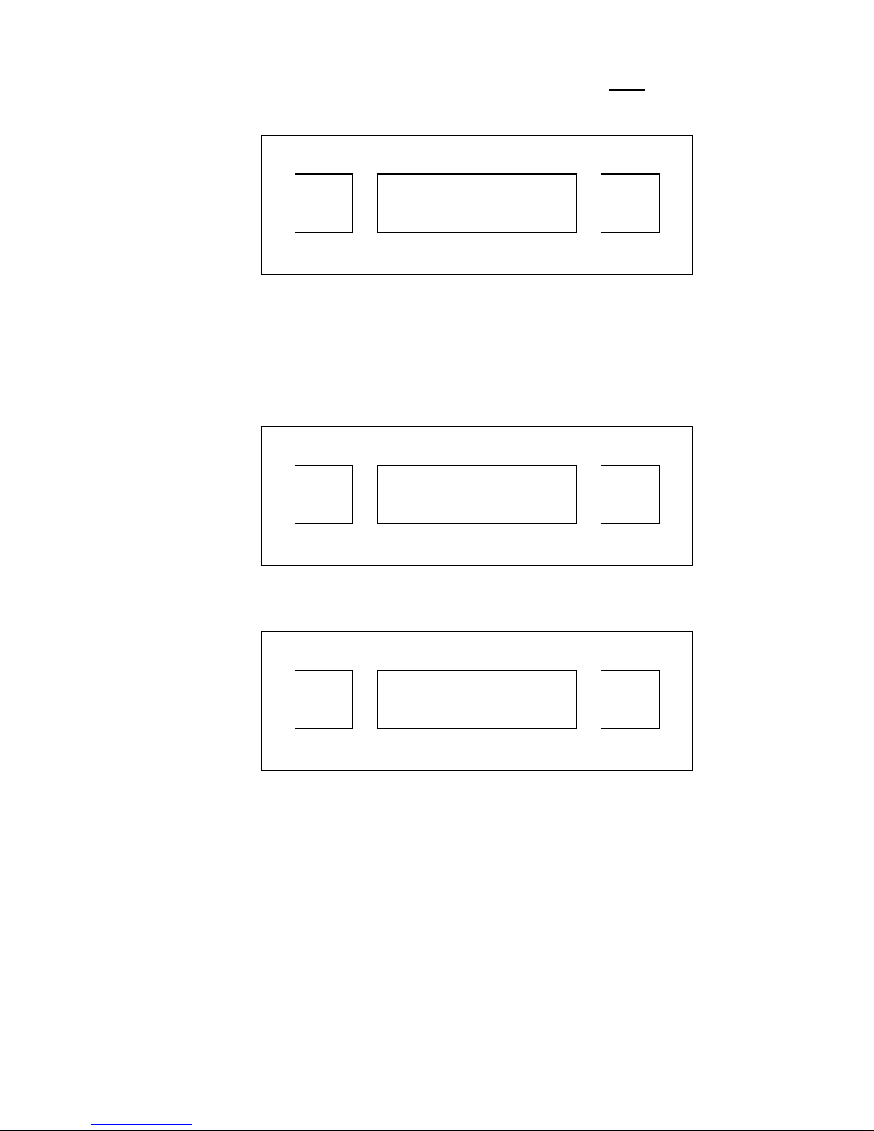
ENT
ENTER FUNCTION:
READ 1.1 (OR 0.5) SPIN
RUN
3. Press the RUN and ENT buttons simultaneous ly and hold them dow n un til
the battery pack capacity is displayed.
When there is 20% capacity remaining, the main menu LCD will flash as
an indication that the battery pack is beginning to run down. It will still be
possible to operate the device for a few spins but the operator should
recharge the battery pack soon. Once there is no longer sufficient
capacity to operate the instrument, it will fail to complete a cycle and the
message CHARGE BATTERY will be displayed.
4. If the device is plugged into an electrical outlet with the ON /OFF switch in
the ON position and the RUN and ENT buttons are pressed
simultaneously, the LCD will display either CHARGING when in the
process of charging or TRICKLE CHARGING if fully charged.
REGARDLESS OF WHAT THE LCD MAY DISPLAY AT ANY GIVEN
TIME DURING THE CHARGING CYCLE, IT IS IMPORTANT TO
ALWAYS ALLOW THE BATTERY PACK TO CHARGE OVERNIGHT OR
AN EQUIVALENT PERIOD OF TIME TO ENSURE A FULL CHARGE.
A FULLY CHARGED BATTERY PACK WILL GENERALLY PROVIDE 75
SPIN CYCLES IF THE CENTRIFUGE IS TURNED OFF BETWEEN
TESTS.
BATT. CAPACITY
XX %

4
SECTION 3
SETUP PROCEDURE
3.1 DISPLAY OPTIONS
This setup procedure will allow the operator to store several functions in the display
option memory until a change is required. These functions include the selection of:
• Tube size - 1.1mm or 0.5mm Inside Di ameter (ID). The device must be set to
the tube size being used. (The ID of capillary tubes may vary slightly - up to
0.1mm.)
• Display language - English, Spanish, French, German or Italian
• HCT value suffix - Choice of displaying % sign or only the value itself
• Decimal point - Choice of displaying hematocrit in whole numbers or with a
decimal point.
Performing this setup procedure eliminates the need to enter these settings into the
device each time a test is performed.
3.2 SETUP MENU AND PROCEDURE
A. With the power ON, the LCD will display the main menu:
ENT
ENTER FUNCTION:
READ 1.1 (OR 0.5) SPIN
RUN
B. S imultaneously press and release the ENT and RUN buttons . The LC D
will change to:
ENT
SETUP
TUBE I.D. NEXT
RUN
5
C. Press ENT to enter the tube size menu. Press ENT again to choose the
1.1mm size or press RUN for 0.5mm.
ENT
SELECT TUBE I.D.
1.1mm 0.5mm
RUN
When the tube size selection is made, the LCD will return to the main
menu.
D. Simultaneously press and release the ENT and RUN buttons. The LC D
will change to:
ENT
SETUP
TUBE I.D. NEXT
RUN
E. Press RUN to enter the language menu. The LCD will display:
ENT
SETUP
LANGUAGE NEXT
RUN
F. Press ENT to select language display, then press RUN repeatedly to
display each of the 5 language options. Press ENT to lock in the
desired language. The LCD will return to the main menu.
 Loading...