

Page 1
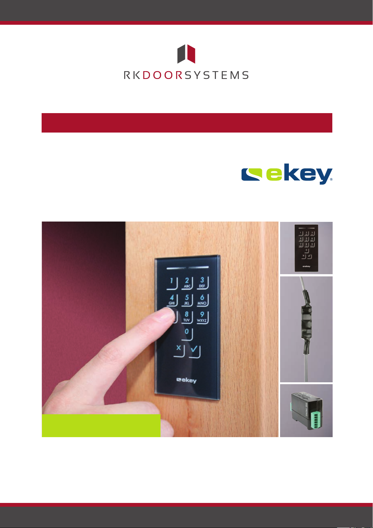
Touchpad Operating Instructions
ekey home
www.rkdoorsystems.co.uk
Page 2
Table of contents
General 2
Note 2
Product liability and limitation of liability 2
Warranty and manufacturer’s warranty 2
Notices, symbols and abbreviations 2
Safety information 3
Life-threatening danger resulting
from electricity 3
Safety against tampering 3
Product description 4
System overview 4
Scope of delivery 4
Proper use and area of application 4
Code pad 4 - 5
Control panels 6
Technical specifications 7
Installation 8
Implementation 8
Implementing devices and establishing
normal mode 8
Entering the admin code 8
Changing the admin code 9 - 10
Setting the automatic back-illumination 11
Setting the brightness of the
back-illumination 11
Setting the relay switching time 12
Setting the signalling that indicates
when a button has been pressed 13
Setting an acoustic signal for opening 14
Storing a user code 14
Use 15
Opening a door 15
Deleting the user code 16
Resetting the system to default settings 17
Updating the software 18
Error displays and troubleshooting 19
Maintenance 19
Dismantling and disposal 20
Declaration of conformity 20
Copyright 20
Page 1
www.rkdoorsystems.co.uk
Page 3
General
ekey biometric systems GmbH operates a quality management system in compliance with EN
ISO 9001:2008 and is certified accordingly.
Note
Product liability
and limitation of
liability
Warranty and
manufacturer’s
warranty
These instructions form a component of the product. Ensure that they are stored in a safe
place. Please contact your dealer for further information about the product.
Safe operation and function of the devices can be impaired in the following situations. Liability
due to malfunctioning is transferred to the operator/user in such cases:
The system devices are not installed, used, maintained and cleaned in accordance
with the instructions.
The system devices are not used within the scope of proper use.
Unauthorised modifications are carried out on the system devices by the operator.
These operating instructions are not subject to updating. Subject to optical and technical
modifications, any liability for errors and misprints is excluded.
Our general terms and conditions apply as valid at the date of purchase. See www.ekey.net.
ekey biometric systems GmbH provides a 24-month warranty for material or processing
defects. This warranty is only valid in the country where the product was purchased. The
product may only be used with original ekey spare parts and accessories.
Notices, symbols and abbreviations
Page 2
www.rkdoorsystems.co.uk
Page 4
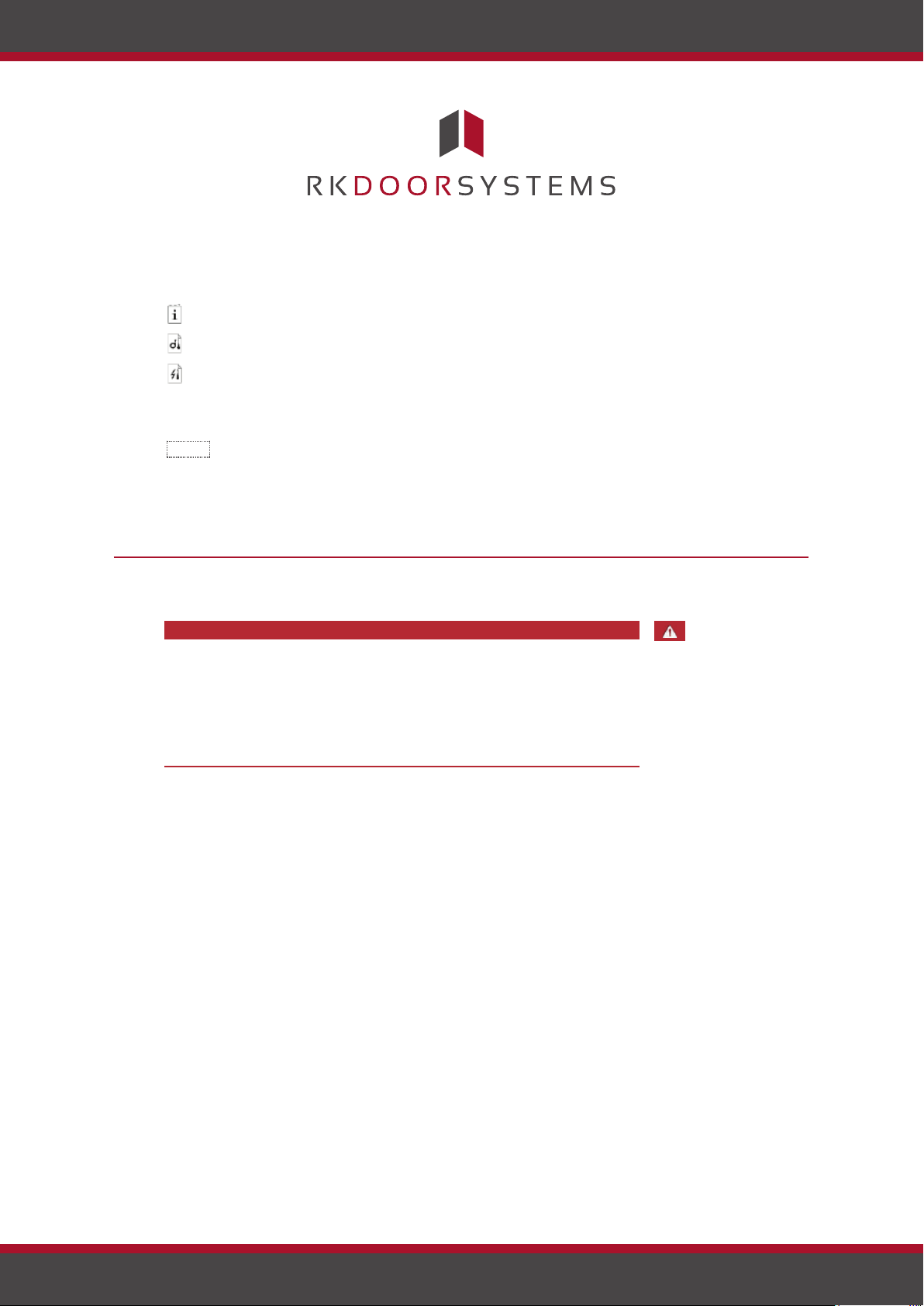
Symbols:
1.
Step-by-step instructions
Reference to sections of this manual
Reference to the mounting instructions
Reference to the wiring diagram
□
Listing without specified order, 1st level
ekey home FS OM
Product names
Button
Buttons
CP
Control panel
Safety against
Abbreviations:
Safety information
All devices are to be operated with safety extra-low
ekey home
voltage (SELV). Only use power supplies rated protection class 2
according to VDE 0140-1.
Failure to do so will result in life-threatening danger due to
electric shock.
Only certified electricians are authorised to carry out the electrical
installation!
Mount the control panel in a safe internal area. This prevents tampering
from the outside.
Safety information
DANGER
Lifethreatening
danger
resulting from
electricity
tampering
Page 3
www.rkdoorsystems.co.uk
Page 5
System
overview
Scope of
Proper use
Code pad
delivery
and area of
application
Product description
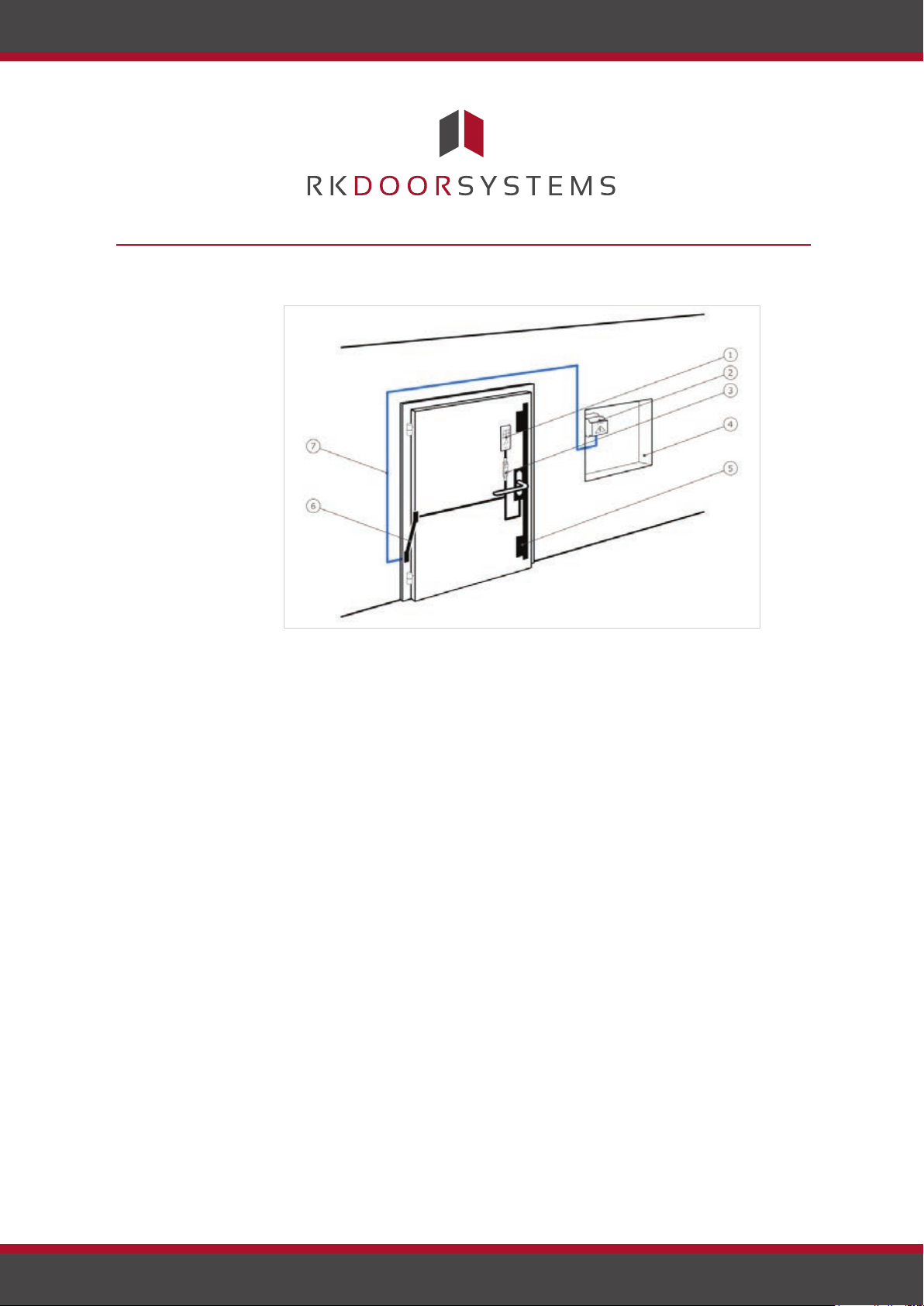
Fig. 1: Overview of the system
This product is an access control system with a non-physical identification
feature (pin code). The system is comprised of a code pad and control
panel. It is available in various makeups and component combinations.
Non-physical identification features (pin codes) are entered and compared
with the stored reference codes. If they match up, the door opens.
The system is primarily designed for opening house doors, apartment
doors and garage doors in homes and businesses.
Product description
1 Code pad
2 Power supply
3 Control panel
4 Distributor
5 Motorised lock
6 Cable transfer
7 Connecting cable
□ Code pad;
□ Control panel;
□ Operating instructions, mounting instructions, wiring diagram;
□ Optional: matching accessories (cable transfer, power supply,
connecting cable, covers, etc.).
Function of the code pad
The code pad captures the pin code by means of the capacitive keypad. It
compares what has been enter
code pad can handle pin codes containing 4 to 8 digits. The digits in the
pin code cannot all be the same; at least one of them must be different.
There are 2 types of pin code: the admin code for configuring the system
and the user code for opening the door.
ed with the stored reference code. The
Page 4
www.rkdoorsystems.co.uk
Page 6
If the code is entered incorrectly 3 times, there will be a 1-minute lock. If the code is then entered incorrectly a further
3 times, there will be a 15- minute lock. There will be a 15-minute lock each time the code is entered incorrectly after
that.
Controls, optical signals and acoustic signals on the code pad
The code pad has 2 sections with controls.
Control Function
Input buttons Enter pin code; select menu item.
Confirmation buttons Confirm pin code input as positive or negative; start menu.
Table 1: Code pad controls
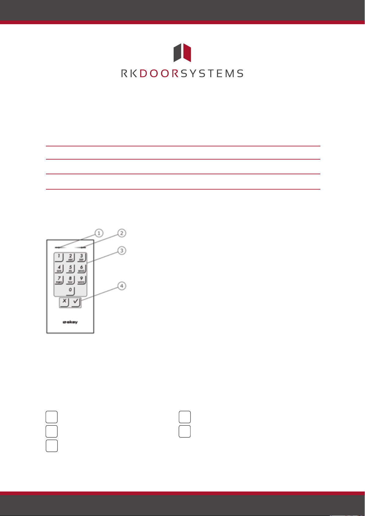
2 status LEDs signal the operating statuses (pin code correct, pin code incorrect, menu item, etc.). An acoustic signal
transmitter signals that the button has been pressed and that access has been enabled.
1 Left status LED
2 Right status LED
3 Input buttons
4 Confirmation buttons
Fig. 2: Code pad overview
The back-illumination of the keypad is blue, dimmable and switches on or off according to the lighting conditions.
Admin menu structure of the code pad
There is a range of menu items available in the admin menu for programming purposes. These can be called via the
buttons.
Button Menu item
1
2
Delete user code
ABC
3
Change admin code
DEF
Table 2: Admin menu structure of the code pad
Store user code
Button Menu item
4
GHI
5
Set the code pad (back-illumination,
JKL
relay switching time, acoustic and
optical signal when button is pressed,
acoustic signal on opening)
Page 5
Reset the system to default settings
www.rkdoorsystems.co.uk
Page 7
Button
Menu item
Set the code pad (back-illumination, relay switching time,
acoustic and optical signal when button is pressed, acoustic
signal on opening)
Table 2: Admin menu structure of the code pad
NOTICE
Product
name
ekey home CP mini 1
ekey home CP micro 1
Figure
Mounting
types
Top hat rail mounting
1 relay, 1 input
Integration into doors
1 relay.
1 Status LEDs
Control panels
Button operation
Function
Press and hold button for 1 sec.
Coupling control panel/code pad.
Press and hold button for 4 secs.
Reset to default settings.
The code pad switches back to normal mode after 10 seconds if nothing
has been pressed. When this happens, any inputs or changes that are
attempted will be rejected.
Control panels are available in 2 makeups. You can only operate a single
code pad per control panel. Any code pad works with any control panel.
Table 3: Control panel makeups
Function of the control panel
The control panel is the actuator of the system. It serves to switch one
relay.
Controls and optical signals of the control panel
The has no controls or optical signals. ekey home CP micro 1
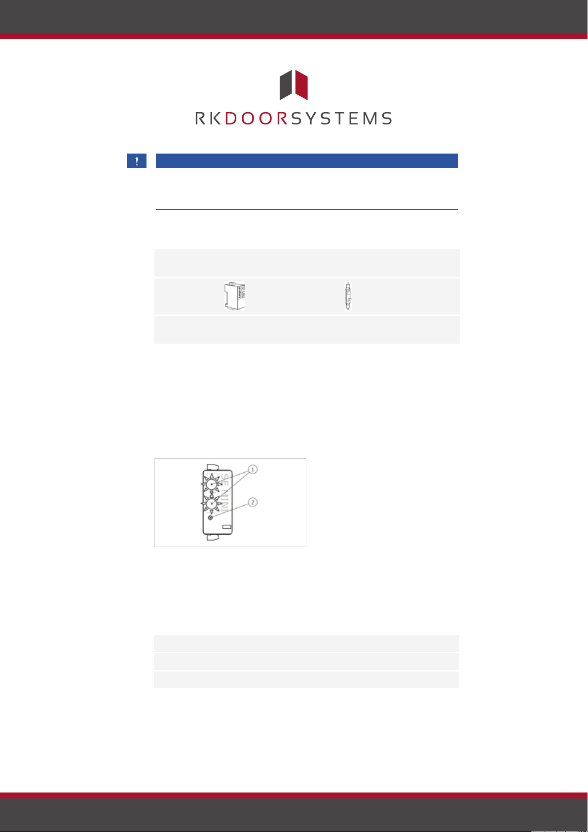
Fig. 3: Overview of the ekey home CP mini 1
The upper status LED indicates if the control panel is connected to the
code pad. The lower status LED indicates when the relay switches.
2 Button
Table 4: Button functions of the ekey home CP mini 1
www.rkdoorsystems.co.uk
Page 6
Page 8
en│7
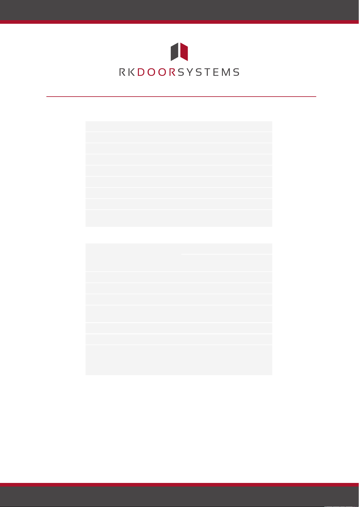
Button operation
Function
Press and hold button for 1 sec.
Coupling control panel/code pad.
Press and hold button for 4 secs.
Reset to default settings.
Table 4: Button functions of the ekey home CP mini 1
Technical specifications
Description
Unit
Value
Supply
VAC/VDC
12-24/8-24
Power input
W
approx. 1
Temperature range
°C
-25 to +70
Memory
Codes
99
Pin code length
Quantity
4-8 digits
Protection class
IP
54 (front side)
Speed
s
<1 (after input is complete)
Operational
lifetime
Button
presses
approx. 1 million
Description
Unit
Value
ekey home CP
mini 1
ekey home CP
micro 1
Supply
VAC/VDC
8-24
-/8-24
Power input
W
approx. 1
approx. 1
Relays
Quantity
1
1
Switching capacity
VDC/A
VAC/A
42/2
42/2
Temperature range
°C
-20 to +70
-25 to +60
Protection class
IP
20
20
Digital inputs (only
Quantity
1
-
Table 5: Technical specifications: ekey home keypad integra 2.0
Technical specifications
potential-free
contacts may be
connected)
Table 6: Technical specifications: andekey home control panel mini 1 ekey home
control panel micro 1
Page 7
www.rkdoorsystems.co.uk
Page 9
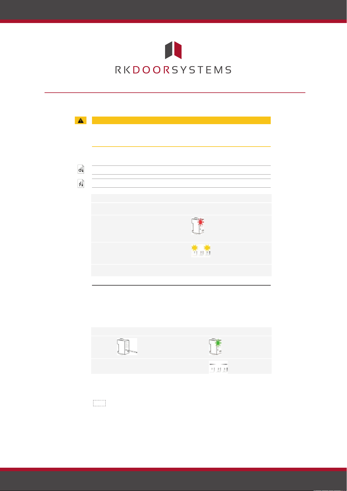
Installation
Step
Action
Display
1.
Ensure safe installation of the
devices. Close the covers.
-
2.
Connect the power supply to the
Only for
ekey home CP
setting.
3.
No action required.
Status LEDs of the code
setting.
4.
If the LEDs fail to light up, check
the wiring and power supply.
-
Step
Action
Description
Display
1.
Press and hold the button
The upper status
2.
No action
-.
Status LEDs are
Implementing
Entering the
Installation
ATTENTION
Mount and cable the product correctly before connecting power.
Possible property damage!
Do not connect the power supply beforehand!
Mount the system in accordance with the supplied mounting instructions.
Cable the system in accordance with the supplied wiring diagram.
devices and
establishing
normal mode
admin code
mains.
: The upper status mini 1
LED on the control panel
flashes red: Default
pad flash yellow
alternately: Default
Implementation
Implementing the devices couples the control panel and the code pad with
one another. The following steps apply to the only. ekey home CP mini 1
These steps are carried out automatically for the . ekey home CP micro 1
LED flashes
green.
off.
with the operating rod for
1 sec.
required.
The devices have now been implemented. The system is in normal mode.
Entering the admin code grants you access to the admin menu. The
admin menu is used to configure the system. The default admin code is
9999. Change the code immediately after implementation.
Page 8
www.rkdoorsystems.co.uk
Page 10
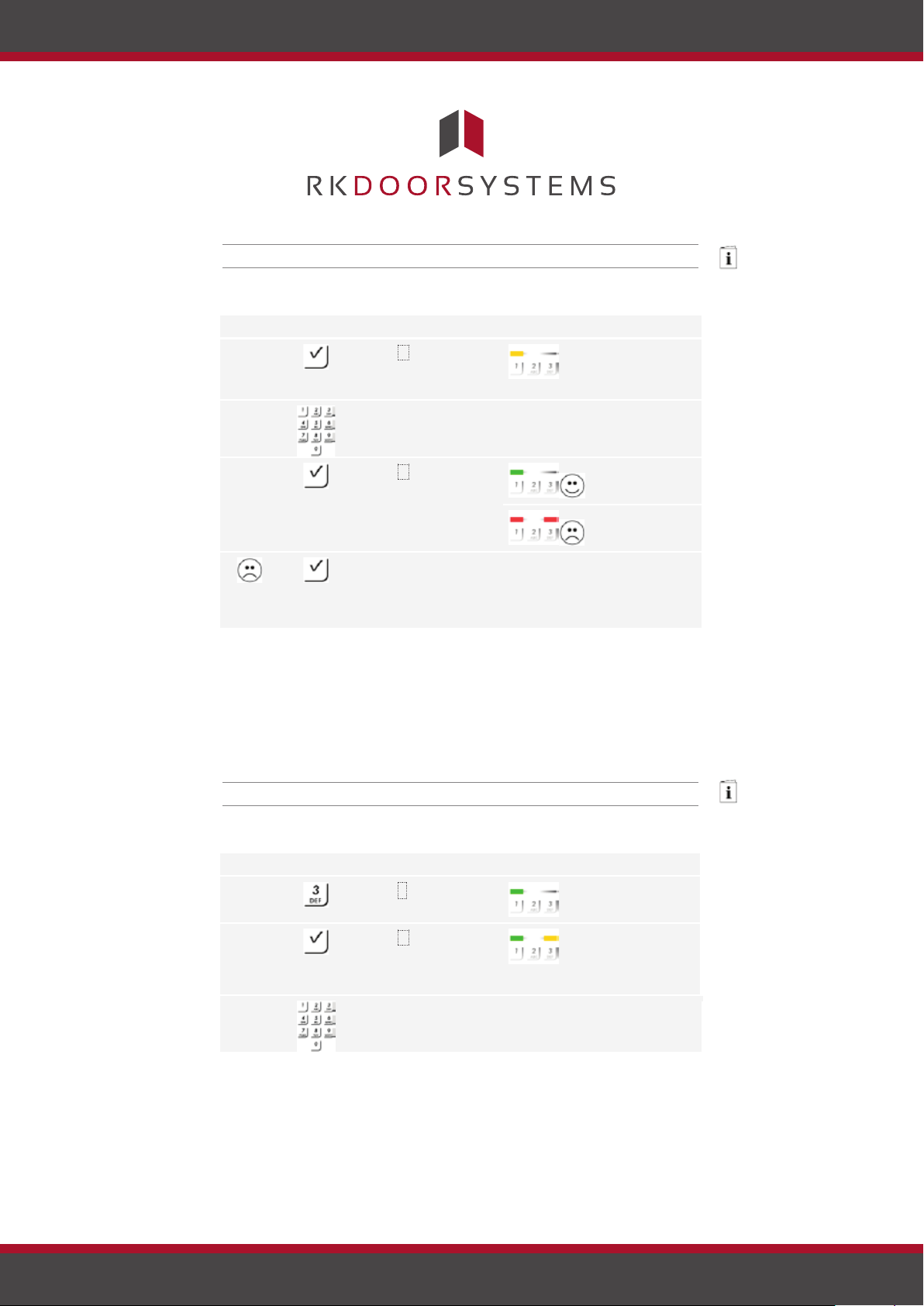
See Changing the admin code, page 9.
Step
Action
Description
Display
1.
Press to start the
The status LED
2.
Enter the admin code
-
-
3.
Press .
The status LED
The status LEDs
The admin code was
-
-
Step
Action
Description
Display
1.
Press 3 .
The status LED
2.
Press .
The status LEDs
right.
3.
Enter the old admin
-
-
Changing the
The system is in normal mode.
process of entering
the admin code.
lights up yellow
on the left.
on the keypad.
not recognised.
lights up green
on the left.
light up red.
Repeat the procedure
beginning at step 1.
The system is in the admin menu. It automatically switches back to
normal mode if you do not press a button within 10 s.
This function allows you to change the existing admin code. The admin
code may contain between 4 and 8 digits. The digits cannot all be the
same; at least one of them must be different.
The admin code can be changed via the admin menu. To get to the admin
menu, enter the admin code.
See Entering the admin code, page 8.
The system is in the admin menu.
admin code
code on the keypad.
Page 9
www.rkdoorsystems.co.uk
lights up green
on the left.
light up green on
the left and
yellow on the
Page 11
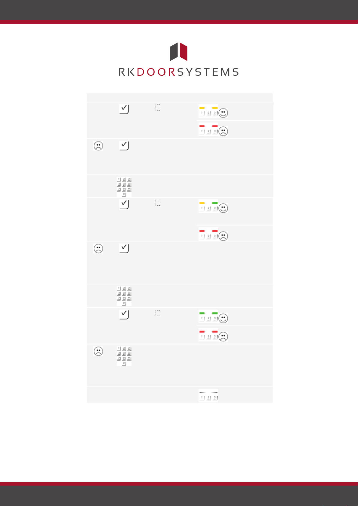
Step
Action
Description
Display
4.
Press .
The status LEDs
The status LEDs
The old admin code
-
-
5.
Enter the new admin
-
-
6.
Press .
The status LEDs
right.
The status LEDs
The required admin
-
-
7.
Enter the new admin
-
-
8.
Press .
The status LEDs
The status LEDs
The two entries do
-
-
9.
No action
-
Status LEDs are
light up yellow.
light up red.
was not recognised.
Enter the admin code
from the beginning
again.
code on the keypad.
code has already
light up yellow
on the left and
green on the
light up red.
been assigned as a
user code. Enter the
admin code from the
beginning again.
code again on the
keypad.
light up green.
light up red.
not match. The new
admin code has not
been saved. Enter
the admin code from
the beginning again.
required.
off.
The new admin code is saved. The system is in normal mode.
Page 10
www.rkdoorsystems.co.uk
Page 12
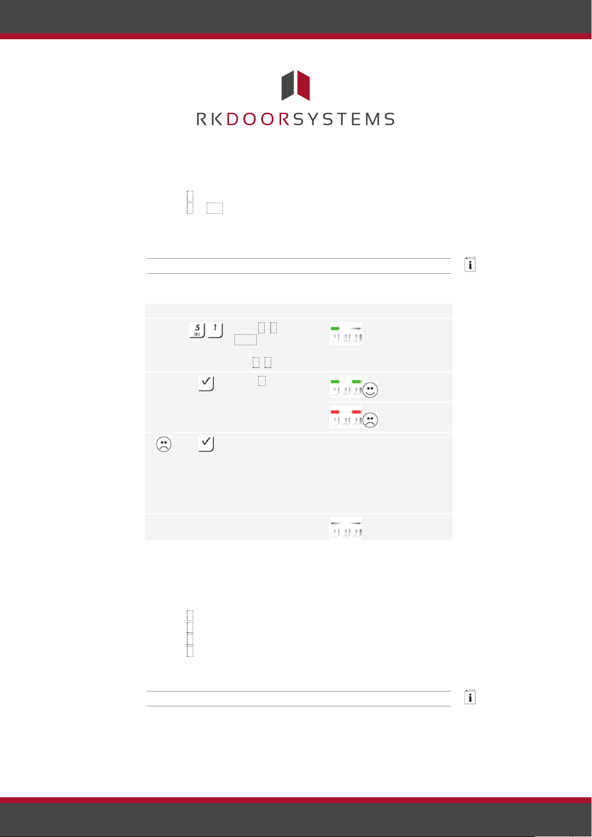
The brightness threshold for switching on the automatic back-illumination
Step
Action
Description
Display
1.
Press 5 , 1 and the
The status LED
2.
Press .
The status LEDs
The status LEDs
Something has been
-
-
3.
No action
-
Status LEDs are
Setting the
Setting the
can be set using percentage values. By default, the brightness threshold
is set to 10%. Enter the required percentage value:
□ 0 = automatic back-illumination off;
□ 1 to 100 = brightness threshold settings between highly
sensitive and highly insensitive.
The automatic back-illumination is set via the admin menu. To get to the
admin menu, enter the admin code.
See Entering the admin code, page 8.
The system is in the admin menu.
automatic
backillumination
value of the required
lights up green
on the left.
brightness threshold.
E.g. 7 , 0 for 70%.
entered incorrectly.
light up green.
light up red.
The brightness
threshold was not
changed. Enter the
admin code from the
beginning again.
required.
off.
The automatic back-illumination has been set. The system is in normal
mode.
The brightness of the back-illumination can be set using 4 predefined
modes. By default, the back-illumination is set to 100%. Enter the
number of the required mode:
□ 0 = back-illumination off;
□ 1 = back-illumination at 33%;
□ 2 = back-illumination at 66%;
□ 3 = back-illumination at 100%
The back-illumination brightness is set via the admin menu. To get to the
admin menu, enter the admin code.
brightness of
the backillumination
See Entering the admin code, page 8.
Page 11
www.rkdoorsystems.co.uk
Page 13
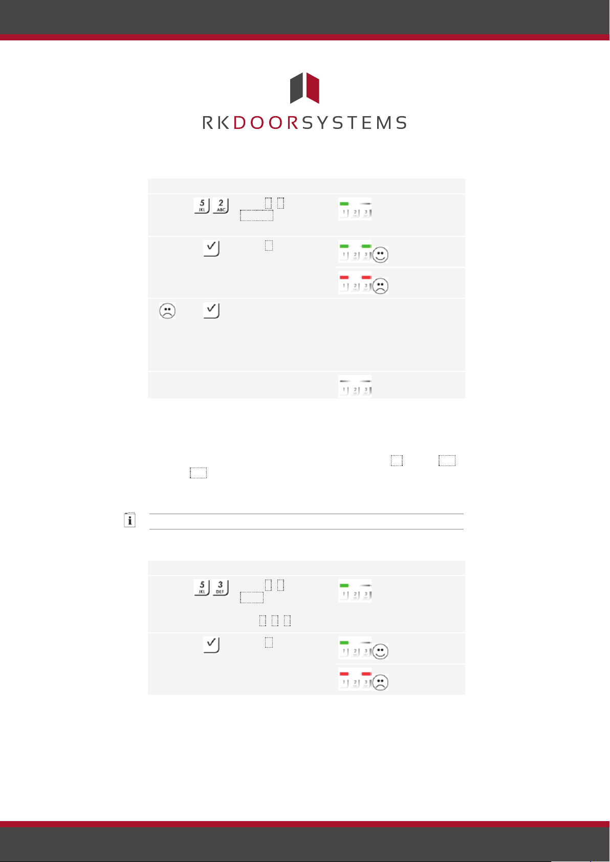
The system is in the admin menu.
Step
Action
Description
Display
1.
Press 5 , 2 and the
The status LED
2.
Press .
The status LEDs
The status LEDs
Something has been
-
-
3.
No action
-
Status LEDs are
Step
Action
Description
Display
1.
Press 5 , 3 and the
The status LED
2.
Press .
The status LEDs
The status LEDs
Setting the
relay
switching time
number of the
lights up green
on the left.
required mode.
entered incorrectly.
light up green.
light up red.
The brightness was
not changed. Enter
the admin code from
the beginning again.
required.
off.
The back-illumination brightness has been set. The system is in normal
mode.
The switching time for the relay can be set up to 99.9 in 0.1-second
increments. By default, the switching time is set to 3 seconds. Enter the
required relay switching time in tenths of a second. E.g.: 60 for 6 s; 100
for 10 s; 300 for 30 s.
The relay switching time is set via the admin menu. To get to the admin
menu, enter the admin code.
See Entering the admin code, page 8.
The system is in the admin menu.
value of the required
relay switching time.
E.g. 1 , 0 , 0 for 10 s.
Page 12
www.rkdoorsystems.co.uk
lights up green
on the left.
light up green.
light up red.
Page 14
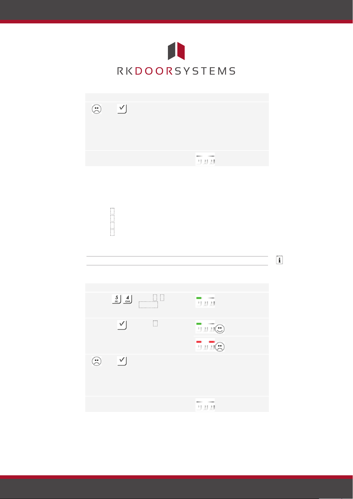
Step
Action
Description
Display
Something has been
-
-
3.
No action
-
Status LEDs are
Step
Action
Description
Display
1.
Press 5 , 4 and the
The status LED
2.
Press .
The status LEDs
The status LEDs
Something has been
-
-
3.
No action
-
Status LEDs are
Setting the
entered incorrectly.
The relay switching
time was not
changed. Enter the
admin code from the
beginning again.
required.
off.
The relay switching time was set. The system is in normal mode.
4 predefined modes can be used to set the acoustic and optical signalling
that indicates when a button has been pressed. By default, the acoustic
and optical signals indicating that a button has been pressed are on. Enter
the number of the required mode:
□ 0 = acoustic and optical signals off;
□ 1 = acoustic signals on and optical signals off;
□ 2 = acoustic signals off and optical signals on;
□ 3 = acoustic and optical signals on.
The signalling to indicate that a button has been pressed is set via the
admin menu. To get to the admin menu, enter the admin code.
See Entering the admin code, page 8.
The system is in the admin menu.
number of the
lights up green
on the left.
required mode.
light up green.
signalling that
indicates when
a button has
been pressed
light up red.
entered incorrectly.
The signalling was
not changed. Enter
the admin code from
the beginning again.
required.
off.
Page 13
www.rkdoorsystems.co.uk
Page 15
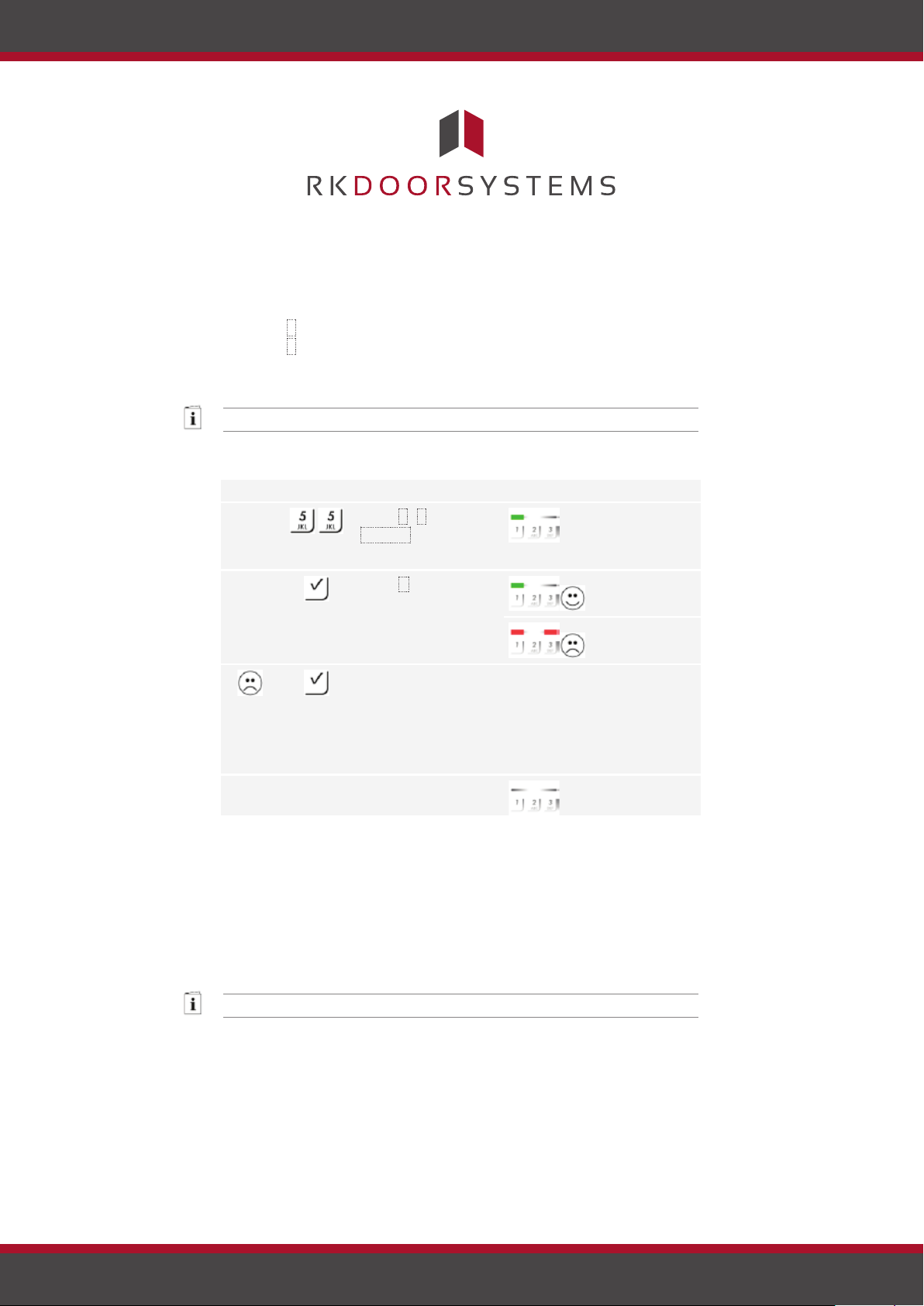
The optical and acoustic signalling to indicate that a button has been
pressed has been set. The system is in normal mode.
Step
Action
Description
Display
1.
The status LED
2.
Press .
The status LEDs
The status LEDs
Something has been
-
-
3.
No action
-
Status LEDs are
Setting an
Storing a user
The acoustic signal for opening can be switched off and on. By default, the
acoustic signal
for opening
acoustic signal is switched on. Enter the number of the required status:
□ 0 for switching off;
□ 1 for switching on.
The acoustic signal for opening is set via the admin menu. To get to the
admin menu, enter the admin code.
See Entering the admin code, page 8.
The system is in the admin menu.
code
Press 5 , 5 and the
number of the
lights up green
on the left.
required status.
entered incorrectly.
light up green.
light up red.
The signalling was
not changed. Enter
the admin code from
the beginning again.
required.
off.
The acoustic signal for opening was set. The system is in normal mode.
The system enables a maximum of 99 user codes to be enrolled.
A user code is any pin code which is used for triggering an action on the
control panel, e.g. opening a door. The user code may contain between 4
and 8 digits. The digits cannot all be the same; at least one of them must
be different.
The user codes are stored via the admin menu. To get to the admin
menu, enter the admin code.
See Entering the admin code, page 8.
The system is in the admin menu.
Page 14
www.rkdoorsystems.co.uk
Page 16
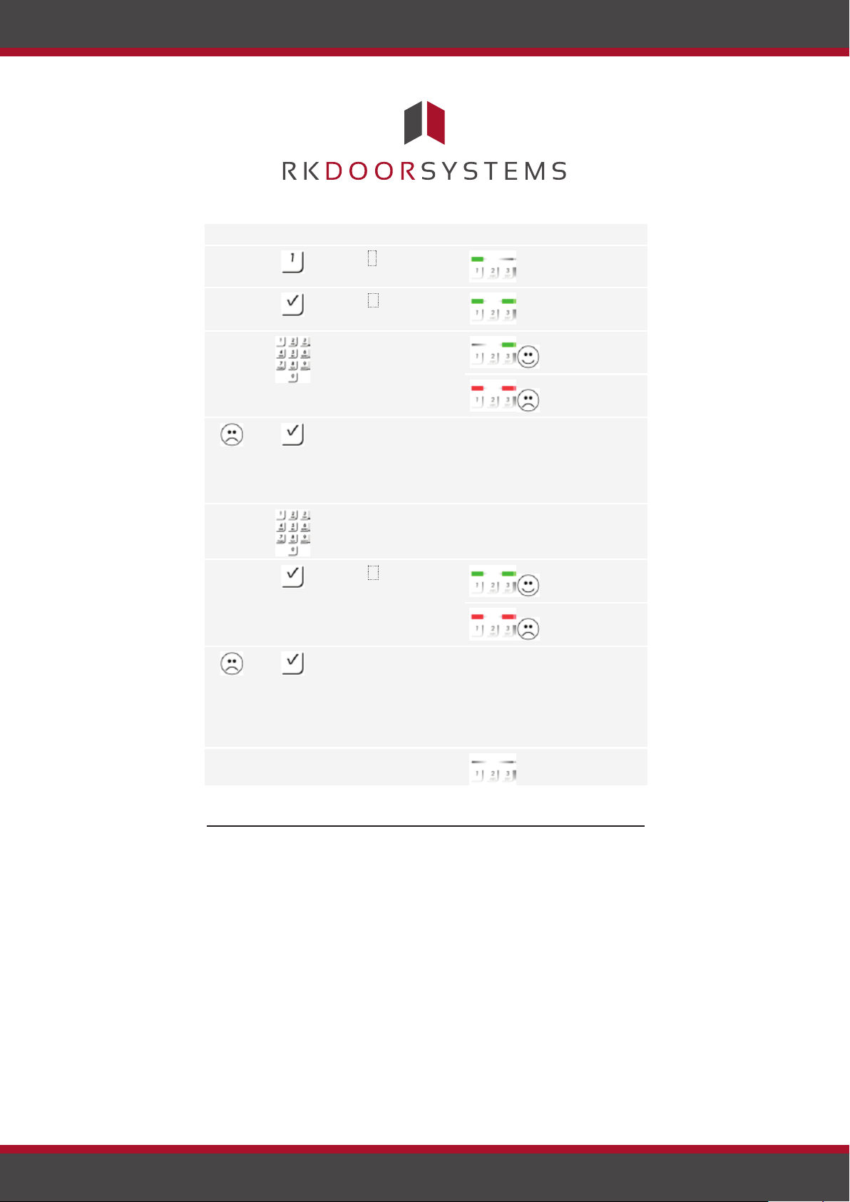
Step
Action
Description
Display
1.
Press 1 .
The status LED
on the left.
2.
Press .
The status LEDs
3.
Enter the required
The status LED
on the right.
The status LEDs
The user code is
-
-
4.
Enter the required
-
-
5.
Press .
The status LEDs
The status LEDs
The two entries do
-
-
6.
No action
-
Status LEDs are
Opening a
lights up green
user code on the
keypad.
already present.
light up green.
lights up green
light up red.
Enter the admin code
from the beginning
again.
user code again on
the keypad.
not match. The user
light up green.
light up red.
code was not stored.
Enter the admin code
from the beginning
again.
required.
off.
The user code was stored. The system is in normal mode.
Use
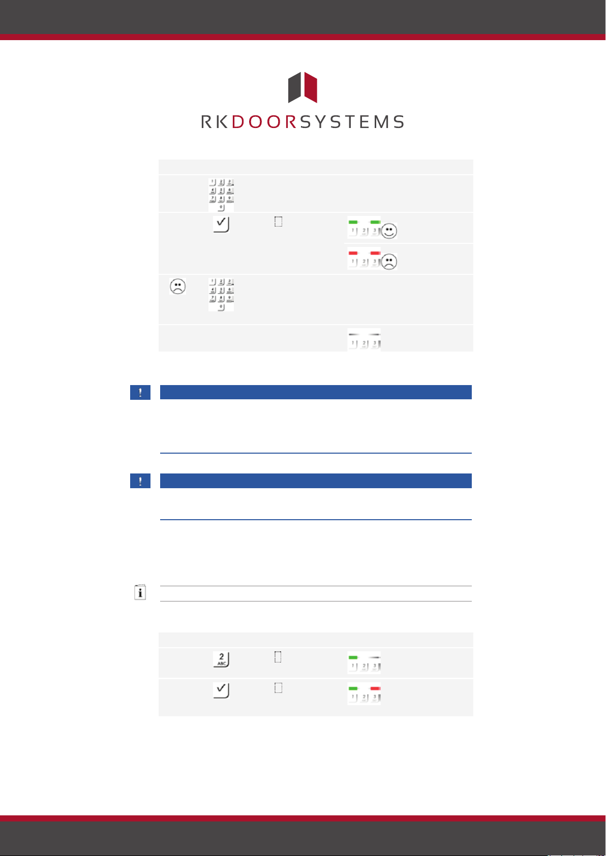
The primary purpose the product is to open doors. The system is in
normal mode.
Page 15
www.rkdoorsystems.co.uk
door
Page 17
Step
Action
Description
Display
1.
Enter a stored user
code on the keypad.
-
-
2.
Press .
The status LEDs
The status LEDs
The user code was
-
-
3.
No action
The door opens.
Status LEDs are
Step
Action
Description
Display
1.
Press 2 .
The status LED
on the left.
2.
Press .
The status LEDs
on the right.
Deleting the
user code
required.
not recognised.
Repeat the procedure
beginning at step 1.
light up green.
light up red.
off.
The system is in normal mode.
NOTICE
If the code is entered incorrectly 3 times, there will be a 1-minute lock. If
the code is entered incorrectly another 3 times, there will be a 15-minute
lock. There will be another 15-minute lock each time the code is entered
incorrectly after that.
NOTICE
You can also open the door using the digital input (PIN 7, 8) on the ekey
. home CP mini 1
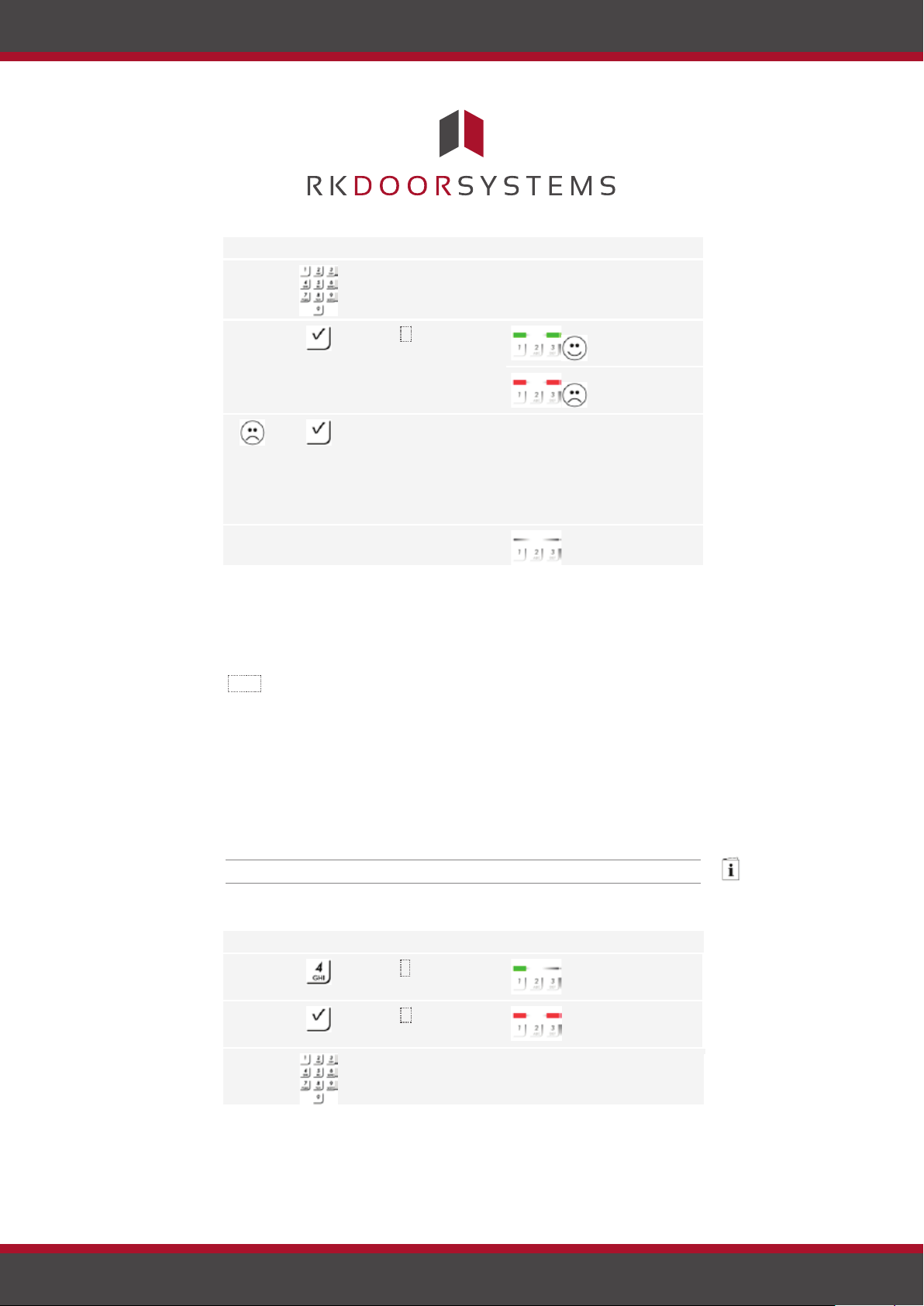
You can delete individual user codes for a user. To do this, you require the
user code to be deleted.
A user code is deleted via the admin menu. To get to the admin menu,
enter the admin code.
See Entering the admin code, page 8.
The system is in the admin menu.
Page 16
www.rkdoorsystems.co.uk
lights up green
light up green on
the left and red
Page 18
Step
Action
Description
Display
3.
Enter the user code
to be deleted on the
-
-
4.
Press .
The status LEDs
The status LEDs
The user code is not
-
-
5.
No action
-
Status LEDs are
Step
Action
Description
Display
1.
Press 4 .
The status LED
2.
Press .
The status LEDs
3.
Enter the admin code
-
-
Resetting the
keypad.
known. The user code
light up green.
light up red.
was not deleted.
Enter the admin code
from the beginning
again.
required.
off.
The user code was deleted. The system is in normal mode.
You can reset the system to its default settings either via the code pad or
using the control panel. Use whichever device is most easily accessible.
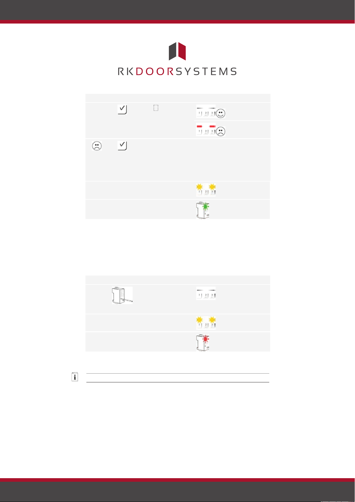
The code pad is reset to its default settings. All user codes will be
irrecoverably deleted. The admin code is reset to the default setting
9999, the relay switching time to 3 seconds, the brightness threshold to
10% and the brightness value to 100%. The acoustic and optical
signalling that indicates when a button has been pressed, and the acoustic
signal for door opening, are both switched on. If the settings are reset via
the control panel, the coupling between the control panel and code pad is
disconnected.
system to
default
settings
Via the code pad
Settings are reset to the default via the admin menu. To get to the admin
menu, enter the admin code.
See Entering the admin code, page 8.
The system is in the admin menu.
lights up green
on the left.
light up red.
on the keypad.
Page 17
www.rkdoorsystems.co.uk
Page 19
Step
Action
Description
Display
4.
Press .
Status LEDs are
The status LEDs
The admin code was
-
-
5.
No action
-
Status LEDs flash
6.
No action
-
The upper status
Step
Action
Description
Display
1.
Press and hold the
Status LEDs are
2.
No action
-
Status LEDs flash
alternately.
3.
No action
-
The upper status
Updating the
off.
light up red.
not recognised. The
system was not
reset. Enter the
admin code from the
beginning again.
required.
required.
yellow
alternately.
LED flashes
green.
The code pad has been reset to its default settings. The system is in
normal mode.
Via the control panel
Resetting to the default settings is only possible with the ekey home CP
and is initiated via the control panel. This can only be undertaken mini 1
for the 1 at the factory. ekey home CP micro
button with the
operating rod for at
off.
least 4 seconds.
software
required.
required.
yellow
LED flashes red.
The control panel and the code pad have been reset to the default
settings. You can now recommission the system.
See Implementing devices and establishing normal mode, page 8.
We are working to constantly improve our products and add new
functionalities. Correspondingly, updates are made available for the code
pad and control panel software. More information about this can be
obtained from your dealer.
Page 18
www.rkdoorsystems.co.uk
Page 20
Error displays and troubleshooting
Display
Meaning
Remedy
The status
The user code was
Enter the user code on the
The status
The numbers in the
Enter a new user code
The status
The required user
Enter a new user code with
The status
An error occurred
Carefully read the
The status
An incorrect user code
After the 1-minute or 15-
Status LEDs
No bus connection to
Check the wiring or
Error displays and troubleshooting
LEDs light up
red.
LEDs light up
red.
LEDs light up
red.
LEDs light up
red.
LED lights up
red on the
right.
flash yellow
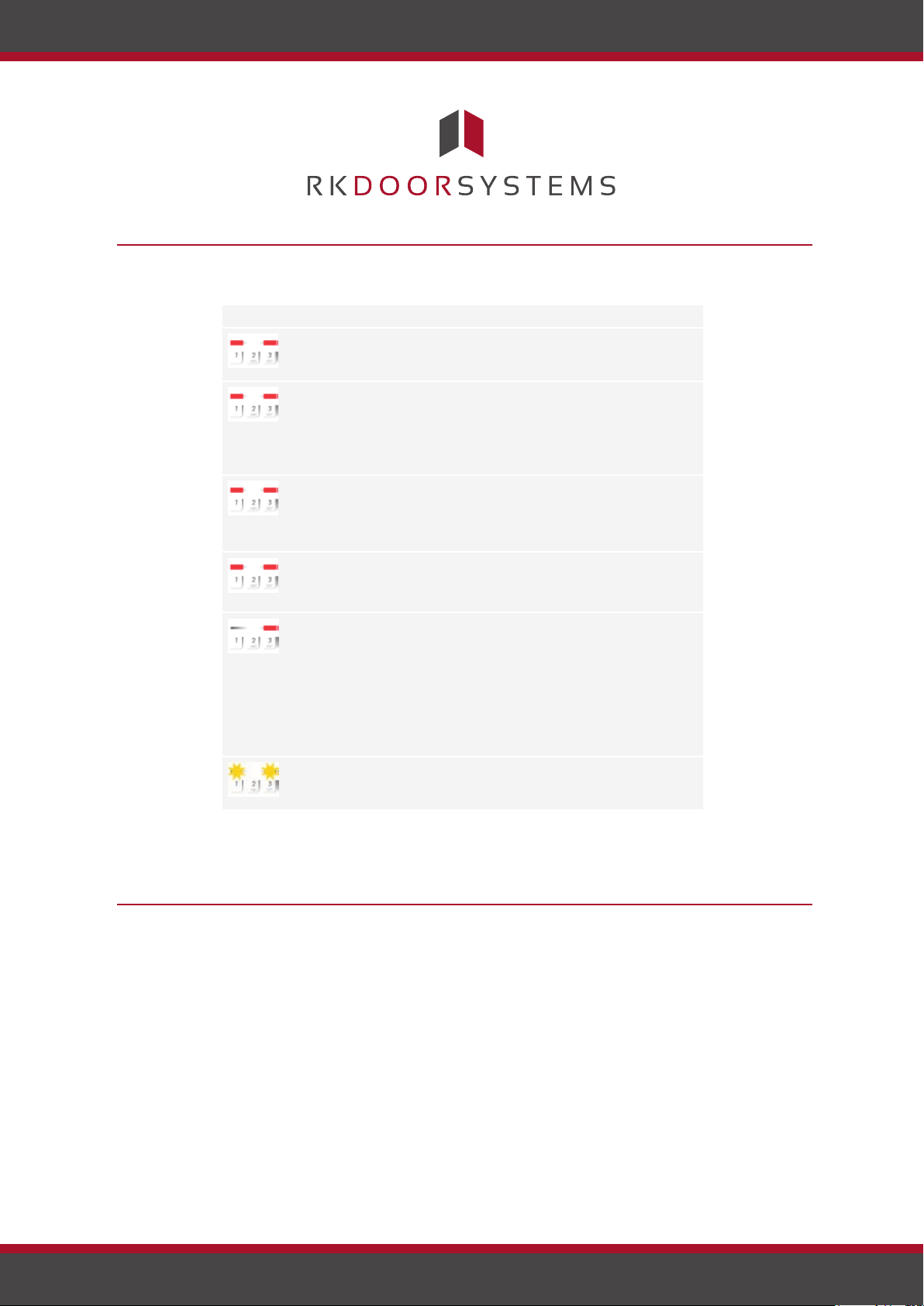
If these suggestions fail to solve the problem, the system must be
returned to ekey biometric systems GmbH to be checked. Please ship the
equipment in suitable packaging. Improper packaging can lead to the
warranty being voided.
alternately.
not recognised.
required user code
are all the same. E.g.:
1111, 3333.
code is too short or
too long. E.g.: 321,
987654321.
when entering menu
items or values.
has been entered 3
times. 1-minute or
15-minute system
lock.
the control panel.
keypad again.
containing at least one
number that is different
from the others. E.g.:
1115, 3733.
a minimum of 4 digits and
a maximum of 8 digits.
E.g.: 4321, 87654321.
description of the required
function again.
minute lock, enter a
correct user code. The 1minute or 15-minute lock
will only count down if the
power supply and data
connection are present
throughout.
implement the device.
Maintenance
The system is largely maintenance-free. However, if the code pad
becomes soiled, clean it with a damp (not wet), non-abrasive cloth. Use
clean water without adding detergent.
Maintenance
Page 19
www.rkdoorsystems.co.uk
Page 21
Dismantling and disposal
Dismantling and disposal
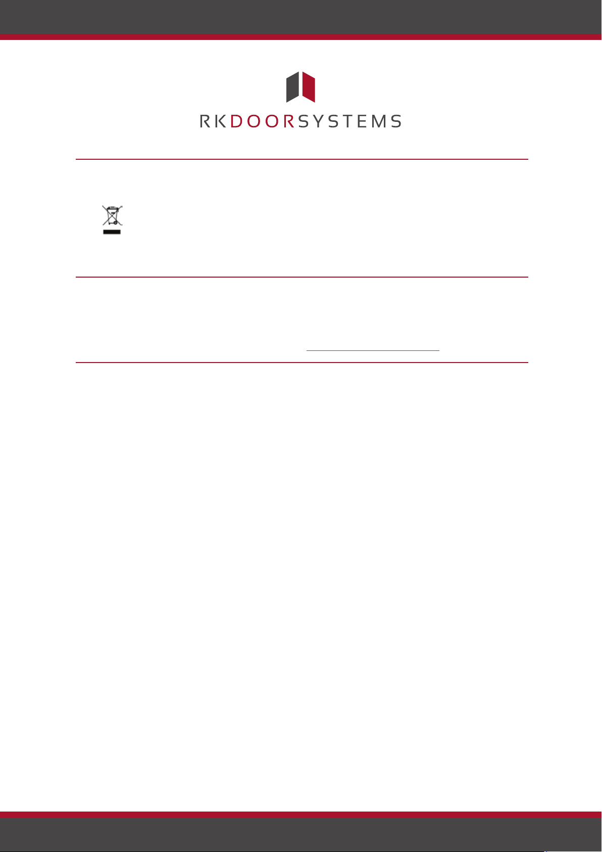
Pursuant to Directive 2002/96/EC of the European Parliament and Council
of 27 January 2003 on the sale, return and environmentally friendly
disposal of electrical and electronic equipment (WEEE) supplied after
13/08/2005, electrical and electronic equipment is to be recycled and may
not be disposed of with household waste. As disposal regulations within
Pursuant to Directive 2002/96/EC of the European Parliament and Council
of 27 January 2003 on the sale, return and environmentally friendly
disposal of electrical and electronic equipment (WEEE) supplied after
13/08/2005, electrical and electronic equipment is to be recycled and may
not be disposed of with household waste. As disposal regulations within
the EU can differ from country to country, please contact your dealer for
further information as necessary.
Dismantling and disposal
Declaration of conformity
ekey biometric systems GmbH hereby declares that the product conforms
to the relevant provisions of the Electromagnetic Compatibility Directive
2004/108/EC of the European Union. The complete text of the declaration
of conformity can be downloaded from http://www.ekey.net/downloads.
Copyright
Copyright © 2013 ekey biometric systems GmbH.
All content, artwork and any ideas contained in these operating
instructions are subject to applicable copyright laws. Any transmission,
relinquishment or transfer of this content or parts thereof to any third
party requires the prior written consent of ekey biometric systems GmbH.
Translated documentation.
Declaration of conformity
Copyright
www.rkdoorsystems.co.uk
Page 20
 Loading...