

eKey home series, home CP mini 1, home CP mini 2, home CP micro 1 Operating Instructions Manual
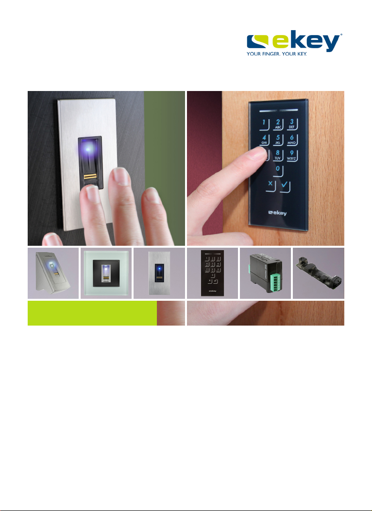
ekey home
en
OPERATING INSTRUCTIONS

en│1
English
Translation of the original instructions – ID203/647/0/554
Table of contents
General ......................................................................................... 3
Note ......................................................................................... 3
Declaration of conformity ............................................................ 3
Product liability and limitation of liability ........................................ 3
Warranty and manufacturer's guarantee ........................................ 3
Copyright protection ................................................................... 3
Notices, symbols, and abbreviations ............................................. 4
Safety information ........................................................................ 5
Risk of electrocution ................................................................... 5
Tamper-proofing ........................................................................ 5
Product description ...................................................................... 6
System overview ........................................................................ 6
Scope of delivery........................................................................ 6
Proper use and area of application ................................................ 6
Finger scanner ........................................................................... 7
Code pad ................................................................................ 10
Control panels ......................................................................... 12
Technical specifications ...............................................................13
Installation and commissioning ...................................................15
Commissioning the system ........................................................ 15
Performing test mode ............................................................... 17
Operating concept .......................................................................18
Configuration of normal mode and usage of the finger scanner
with the app ................................................................................19
Downloading the app ................................................................ 19
Coupling a mobile device for the first time .................................... 20
Changing security codes ............................................................ 21
Storing fingers ......................................................................... 22
Disabling Bluetooth................................................................... 23
Coupling additional mobile devices .............................................. 23
Managing multiple Bluetooth finger scanners ................................ 24
Storing the user coupling code ................................................... 25
Resetting the app security code .................................................. 25
Protecting the system in the event that the mobile device is lost ..... 26
Opening a door ........................................................................ 27

2│en
Configuration of normal mode and usage of the finger scanner
with administrator fingers ........................................................... 29
Storing administrator fingers and configuring normal mode ............. 29
Storing user fingers .................................................................. 31
Storing RFID transponders ......................................................... 33
Opening a door ........................................................................ 35
Deleting user fingers ................................................................. 37
Deleting RFID transponders ....................................................... 38
Deleting all user fingers and RFID transponders ............................ 39
Configuration of normal mode and usage of the code pad with
shortcuts ..................................................................................... 41
Entering the admin code ............................................................ 41
Changing the admin code .......................................................... 43
Setting the automatic back-illumination ....................................... 45
Setting the brightness of the back-illumination .............................. 46
Setting the relay switching duration ............................................ 47
Setting the signaling that indicates when a button has been pressed 48
Setting an acoustic signal for opening .......................................... 49
Storing the user code ................................................................ 50
Opening a door ........................................................................ 52
Deleting the user code .............................................................. 53
Resetting the system to default settings ..................................... 54
Via the app .............................................................................. 55
Via the finger scanner ............................................................... 55
Via the code pad ...................................................................... 57
Via the control panel ................................................................. 58
Via the digital input (ekey home control panel micro 1 only)............ 59
Updating the software ................................................................. 59
Error displays and troubleshooting .............................................. 60
Finger scanner ......................................................................... 60
Code pad ................................................................................ 61
Maintenance ................................................................................ 62
Disposal ....................................................................................... 62

en│3
General
ekey biometric systems GmbH operates a quality management system in
compliance with EN ISO 9001:2008 and is certified accordingly.
Read these operating instructions carefully before use. These operating
instructions form a component of the product. Ensure that they are stored
in a safe place. These operating instructions contain important information
on the product; in particular, its proper use, safety, installation,
commissioning, usage, maintenance, and disposal.
Please contact your dealer for further information about the product.
A large-font version of these operating instructions is available at
http://www.ekey.net.
These operating instructions are not subject to updating. We reserve the
right to make technical modifications and change the product's
appearance; any liability for errors and misprints is excluded.
ekey biometric systems GmbH hereby declares that the product conforms
to the relevant European Union directives.
Safe operation and function of the devices can be impaired in the
following situations. Liability due to malfunctioning is transferred to the
operator/user in such cases:
□ The system devices are not installed, used, maintained, or
cleaned in accordance with the instructions
□ The system devices are not used within the scope of proper use
□ Unauthorized modifications are carried out on the system
devices by the operator.
The version of our general terms and conditions in force on the date of
purchase shall apply. See http://www.ekey.net.
Copyright © 2017 ekey biometric systems GmbH.
All content, artwork, and any ideas contained in these operating
instructions are subject to applicable copyright laws. Any transmission,
relinquishment, or transfer of this content or parts thereof to any third
party requires the prior written consent of ekey biometric systems GmbH.
Translation of the original documentation.
Note
Declaration of
conformity
Product
liability and
limitation of
liability
Warranty and
manufacturer'
s guarantee
Copyright
protection
4│en
Notices, symbols, and abbreviations
DANGER
Denotes imminent danger which could lead to death or serious
injuries.
ATTENTION
Denotes possible property damage which cannot result in injuries.
NOTICE
Denotes additional information and useful tips.
Symbols:
1.
Step-by-step instructions
References to sections of these instructions
References to the mounting instructions
References to the wiring diagram
□
Listing without specified order, 1st level
Displayed value
Displayed values
ekey home CP
mini
Product names
MENU ITEM
Menu items
Button
Buttons

en│5
Abbreviations and terminology:
BT
Bluetooth
CP
Control panel
FAR
False acceptance rate
FRR
False rejection rate
FS
Finger scanner
IN
integra
KP
keypad
OM
Outlet-mounted
RFID
Radio-frequency identification
WM
Wall-mounted
Fingerprint
The biometric information extracted from the
fingerprint
Normal mode
Default operating status in which the system is
operated.
Registration unit
Finger scanner or code pad
Safety information
DANGER
All ekey home devices are to be operated with safety extra-low
voltage (SELV). Only use power supplies rated protection class 2
according to VDE 0140-1.
Failure to do so will create a risk of fatal electrocution.
Only certified electricians are authorized to carry out the electrical
installation work!
Mount the control panel in a secure internal area. This prevents tampering
from the outside.
Risk of
electrocution
Tamperproofing
6│en
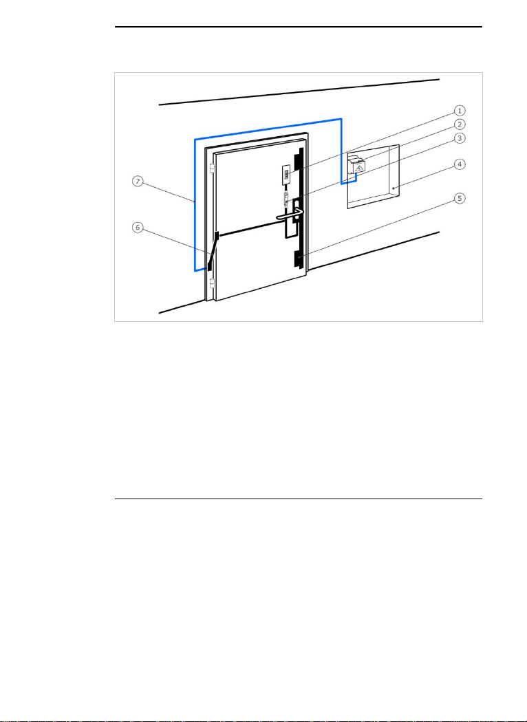
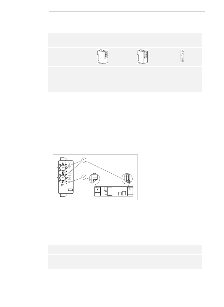
Product description
Fig. 1: Overview of the system
1 Registration unit
2 Power supply
3 Control panel
4 Distributor box
5 Motorized lock
6 Cable transfer
7 Connecting cable
□ Registration unit
□ RFID transponder for finger scanners with RFID function
□ Control panel
□ Operating instructions, mounting instructions, wiring diagram
□ Optional: matching accessories (cable transfer, power supply,
connecting cable, covers, etc.).
This product is an access control system with a biometric or mental
identification feature (finger scan or pin code). The system is comprised of
a registration unit and control panel. It is available in various models and
component combinations.
The biometric access control system detects the characteristics (minutiae)
of the fingerprint contours, compares them to the biometric information
saved from the reference fingerprint image, and opens the door in the
event of a match. One variant allows the user to be identified and the
door opened by means of an RFID transponder.
The non-physical access control system detects the pin codes which are
entered, compares them to the stored reference codes, and opens the
door in the event of a match.
The system is primarily designed for opening house doors, apartment
doors, and garage doors in homes and businesses.
System
overview
Scope of
delivery
Proper use
and area of
application
en│7
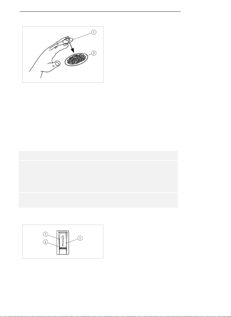
Function of the finger scanner
1 Front phalanx
2 Fingerprint
Fig. 2: Fingerprint
The finger scanner detects the fingerprint by means of a line sensor and
subsequently processes it. It compares the result with that of the
biometric information saved from the reference fingerprint image and
opens the door in the event of a match. The finger scanner only works
correctly and reliably with the front phalanx print. Swipe your finger
steadily and evenly over the sensor in the correct position.
The variants with RFID function detect and identify RFID transponders.
Finger scanner controls
Controls
Function
Finger swipe
area
Store fingers by 'swiping the finger' evenly downward
over the sensor.
Identification by 'holding up the RFID transponder',
which involves holding an RFID transponder over the
finger swipe area of the finger scanner.
Sensor
System programming by 'Finger Touch', a short, rapid
touch of the sensor with the finger.
Table 1: Finger scanner controls
1 Right guiding edge
2 Sensor
3 Left guiding edge
Fig. 3: Finger swipe area and sensor
Finger scanner
8│en
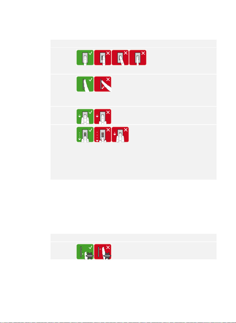
Correct operation of the finger scanner
Incorrect operation will impair the function of the finger scanner.
'Swiping the finger':
Step
Figure
Description
1st
Hold your finger straight
and place it centrally
between the guiding edges.
Do not twist the finger.
2nd
Place the joint of the front
phalanx directly onto the
sensor. Place your finger
flat onto the finger swipe
area.
3rd
Stretch out the neighboring
fingers.
4th
Move your finger evenly
downward over the sensor.
Move the whole hand
simultaneously. Swipe the
front phalanx fully over the
sensor in order to achieve
optimal results. The
movement takes approx. 1
second.
General hints for achieving a good-quality fingerprint
□ The index, middle, and ring fingers work best. The thumb and
small finger supply fingerprints that are difficult to analyze.
□ In the case of fingers that are frequently wet, store the images
with wet fingers.
□ Children's fingerprints work from approx. 5 years of age.
'Finger Touch':
Step
Figure
Description
1st
Briefly touch the sensor
with your finger.
en│9
'Holding up the RFID transponder':
NOTICE
The 'holding up the RFID transponder' option is only available for finger
scanners with an RFID function.
Step
Figure
Description
1st
Hold the RFID transponder
face parallel to the finger
swipe area of the finger
scanner at a distance of 1
to 5 cm.
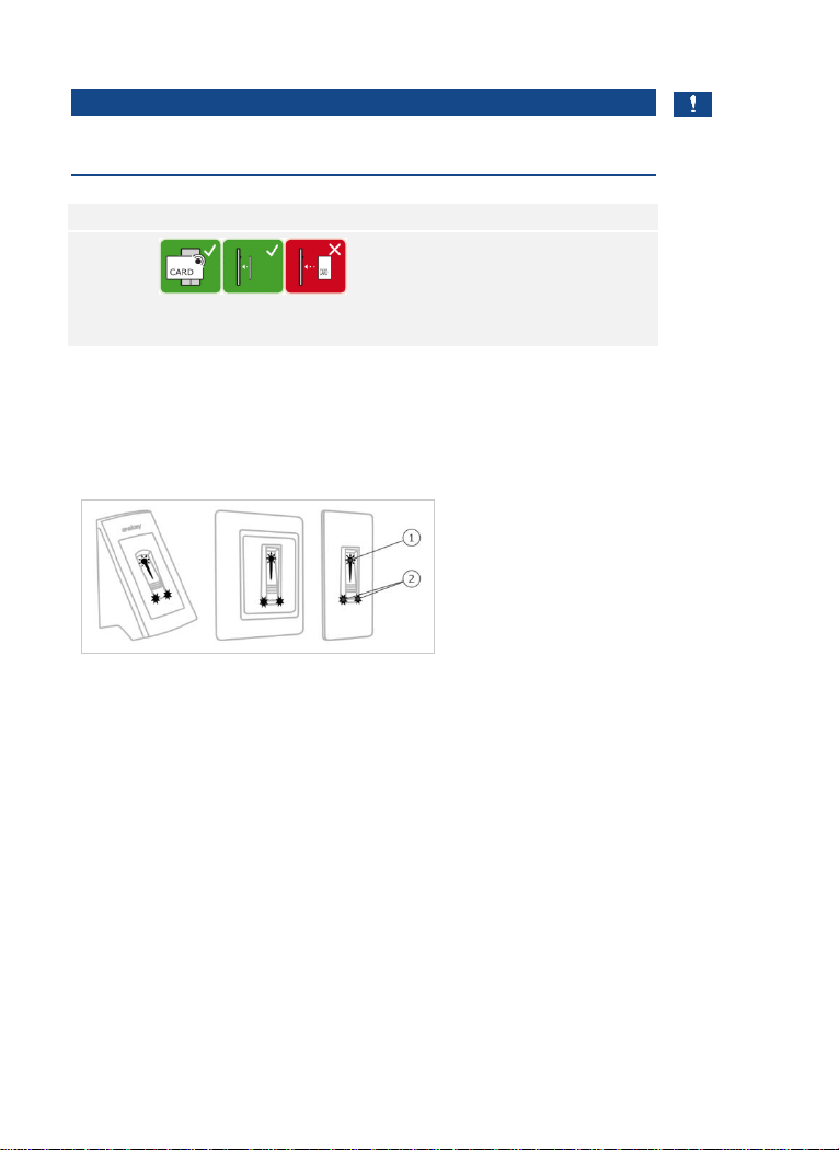
Optical signals on the finger scanner
There are 2 types of LED:
□ Status LED for operating status
□ Function LED for indicating the function of the overall system.
1 Status LED
2 Function LEDs
Fig. 4: Optical signals on the finger scanner
10│en
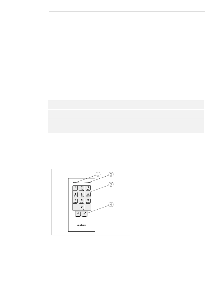
Function of the code pad
The code pad captures the pin code with the capacitive keypad. The code
pad compares what has been entered with the stored reference codes.
The code pad can handle pin codes containing 4 to 8 digits. The digits in
the pin code cannot all be the same; at least one of them must be
different. There are 2 types of pin code: The admin code for configuring
the system and the user code for opening doors.
If the code is entered incorrectly 3 times, there will be a 1-minute lock. If
the code is then entered incorrectly a further 3 times, there will be a 15minute lock. There will be a 15-minute lock each time the code is entered
incorrectly after that.
Controls, optical signals, and acoustic signals on the code pad
The code pad has 2 sections with controls.
Controls
Function
Input buttons
Enter pin code; select menu item.
Confirmation buttons
Confirm pin code input as positive or negative;
start menu.
Table 2: Code pad controls
2 status LEDs signal the operating statuses (pin code correct, pin code
incorrect, menu item, etc.). An acoustic signal transmitter signals that the
button has been pressed and that access has been enabled.
1 Left status LED
2 Right status LED
3 Input buttons
4 Confirmation buttons
Fig. 5: Code pad overview
The back-illumination of the keypad is blue, dimmable, and switches on or
off according to the lighting conditions.
Code pad
en│11
Admin menu structure of the code pad
There is a range of menu items available in the Admin menu for
programming purposes. These can be called via the buttons.
Button
Menu item
Store user code
Delete user code
Change admin code
Reset system to default settings
Set code pad (back-illumination, relay switching duration,
acoustic and optical signal when button is pressed, acoustic
signal on opening)
Table 3: Admin menu structure of the code pad
NOTICE
The code pad switches back to normal mode after 10 seconds if nothing
has been pressed. When this happens, any inputs or changes that are
attempted will be rejected.
12│en
Control panels are available in 2 models. You can only operate a single
registration unit per control panel. Any registration unit works with any
control panel.
Product
name
ekey home CP
mini 1
ekey home CP
mini 2
ekey home CP
micro 1
Figure
Mounting
type
Mounting DIN
rails
1 relay
1 digital input
Mounting DIN
rails
2 relays
Integration into
doors
1 relay,
1 digital input
Table 4: Control panel models and variants
Function of the control panel
The control panel is the actuator of the system. The control panel
switches one or two relays and makes a digital input available for the
models with one relay. The model with two relays does not have a digital
input.
Controls and optical signals of the control panel
1 Status LED
2 Button
Fig. 6: Overview of
ekey home CP mini 1/2
and
ekey home CP micro 1
ekey home control panel mini 1/2: The upper status LED indicates
whether the control panel is connected to the finger scanner. The lower
status LED indicates when a relay switches.
ekey home control panel micro 1: The LED indicates whether the control
panel is connected to the finger scanner and whether the relay switches.
Button operation
Function
Press and hold button for
4 sec.
Reset to default settings.
Table 5: Button operation of ekey home CP mini 1/2 and ekey home CP micro 1
Control panels

en│13
Technical specifications
Name
Unit
Values
Supply
VDC
8–24
Power consumption
W
Heating off: 1
Heating on: 4
Temperature range
°C
-25 to +70
Memory
Fingers
99
RFID
transponders
99 (only for FS with RFID function)
Security
FAR
FRR
1:10,000,000
1:100
IP code
IP
WM, IN
: 54 (front side)
OM
: 44 (with
ekey frame FS OM
)
Reaction time
sec
1–2
Operational
lifetime
Finger scans
Approx. 10 million
RFID
(only for finger
scanners with RFID
function)
Interface
ISO14443A
Transponder
type
MIFARE DESFire EV1 with at least
1 KB of memory
Table 6: Technical specifications: ekey home finger scanner
Name
Unit
Values
Supply
VDC
8–24
Power consumption
W
Approx. 1
Temperature range
°C
-25 to +70
Memory
Codes
99
Pin code length
Quantity
4–8 digits
IP code
IP
54 (front side)
Speed
sec
<1 (after input is complete)
Operational
lifetime
Button
presses
Approx. 1 million
Table 7: Technical specifications: ekey home keypad integra 2.0

14│en
Name
Unit
Values
ekey
home CP
mini 1
ekey
home CP
mini 2
ekey
home CP
micro 1
Supply
VDC
8–24
8–24
8–24
Power consumption
W
Approx. 1
Approx. 1
Approx. 1
Relay
Quantity
1 2 1
Relay switching
capacity
VAC/A
VDC/A
42/2
42/2
42/2
Temperature range
°C
-20 to
+70
-20 to
+70
-25 to
+60
IP code
IP
20
20
20
Digital inputs (only
potential-free
contacts may be
connected)
Quantity
1 0 1
Table 8: Technical specifications: ekey home control panel mini 1/2 and ekey
home control panel micro 1
en│15
Installation and commissioning
ATTENTION
Mount and cable the product correctly before connecting power.
Failure to do so will create a risk of possible property damage!
Do not connect the power supply beforehand!
Mount the system in accordance with the supplied mounting instructions.
Cable the system in accordance with the supplied wiring diagram.
Using the finger scanner
Step
Action
Display
1st
Ensure safe installation of the
devices. Close the covers.
-
2nd
Connect the power supply to the
mains.
The top status LED on the
ekey home CP mini 1
and
ekey home CP mini 2
alternates between
flashing green and orange
and the LED on the
ekey
home CP micro 1
flashes
green slowly: default
setting.
3rd
No action required.
Status LED on the finger
scanner flashes blue.
Commissioning the system

16│en
Using the code pad
Step
Action
Display
1st
Ensure safe installation of the
devices. Close the covers.
-
2nd
Connect the power supply to the
mains.
The top status LED on the
ekey home CP mini 1
and
ekey home CP mini 2
alternates between
flashing green and orange
and the LED on the
ekey
home CP micro 1
flashes
green slowly: default
setting.
3rd
No action required.
Status LEDs of the code
pad do not light up.
The devices have now been commissioned.
If you are using a Bluetooth finger scanner, the finger scanner is ready for
storing administrator fingers and for creating the coupling between the
finger scanner and mobile device.
The code pad is in normal mode.
en│17
You can check the cabling with the aid of test mode. Test mode only
works for finger scanners.
NOTICE
A test can only take place if no administrator fingers have been stored
and no mobile device has been coupled.
Connect the mains supply and perform the test within 10 minutes. If 10
minutes have elapsed, the mains supply will have to be reconnected in
order to conduct this test.
Step
Action
Description
Display
1st
Place a finger on the
sensor and leave it there
for longer than 3 sec.
The status LED
flashes blue.
2nd
Remove the finger from
the sensor within the next
2 sec.
The status LED
on the finger
scanner lights up
green. The top
status LED on
the
ekey home
CP mini 1
or
ekey home CP
mini 2
lights up
green and the
LED on the
ekey
home CP micro 1
lights up green.
The relay switches.
NOTICE
This means that you can keep your finger on the sensor for up to 5 sec. If
the finger is kept on the sensor for longer than this, the relay will not
switch.
Performing
test mode

18│en
Operating concept
Different operating concepts are available, depending on the registration
unit:
□ ekey home app – administration of the Bluetooth finger scanner
by means of a mobile device
□ ekey administrator finger – administration of the finger scanner
by means of administrator fingers
□ ekey admin code – administration of the code pad by means of
shortcuts.
Go to the operating concept that relates to the registration unit you have
purchased.
See “Configuration of normal mode and usage of the finger scanner with
the app”, page 19.
See “Configuration of normal mode and usage of the finger scanner with
administrator fingers”, page 29.
See “Configuration of normal mode and usage of the code pad with
shortcuts”, page 41.

en│19
Configuration of normal mode and usage
of the finger scanner with the app
NOTICE
The ekey home app can only be used in conjunction with the Bluetooth
finger scanner.
The system must have been commissioned before you start your system
administration.
See “Commissioning the system”, page 15.
The Bluetooth finger scanner is ready to create the coupling between the
Bluetooth finger scanner and mobile device. The ekey home app is used
for programming the system. Doors can also be opened via the app.
The app is available for Apple iOS and Google Android. Download the ekey
home app
from the App Store or Google Play. To find it, enter the search
term ekey home app.
Downloading
the app

20│en
For first-time coupling, you will need the device coupling code and the app
security code. Both codes are factory-set as 9999 .
Step
Instruction
Display
1st
Start the
ekey home app
.
2nd
Touch the input field (Android) or press Search
(iOS). The app searches for available Bluetooth
devices.
-
3rd
Select your ekey Bluetooth finger scanner.
-
4th
Android only: Press Login.
-
5th
Enter the default device coupling code 9999 .
The status
LED lights
up blue,
the lefthand
function
LED lights
up orange.
6th
Press Next. The mobile device is coupled with
the Bluetooth finger scanner.
7th
Enter a new 6-digit device coupling code. For
security reasons, you must change the default
device coupling code the first time you perform
the system admin coupling process. Make a
note of this code, as you will need it to couple
additional mobile devices.
-
8th
Write your new device coupling code here:
____________________________________.
9th
Press Change (Android) or Next (iOS).
10th
Enter the default app security code 9999 .
11th
Press Next.
The coupling between the Bluetooth finger scanner and the mobile device
is established. The system is in normal mode.
You can now start programming and managing the finger scan access
control system via the ekey home app.
NOTICE
The intuitive ekey home app is now all you need for the administration of
your Bluetooth finger scanner. Tap the required functions in the app and
follow the instructions on the display.
Coupling a
mobile device
for the first
time

en│21
You can change all security codes at any time:
□ the app security code
□ the admin coupling code
□ the user coupling code
□ the control panel security code
NOTICE
The 4 to 6-digit app security code is required for the app security prompt.
You can disable the prompt to enter the app security code under
ADMINISTRATION if your mobile device supports secure lock
mechanisms (fingerprint, code, etc.).
Step
Instruction
1st
Select ADMINISTRATION.
2nd
Select CHANGE SECURITY CODES.
3rd
Change the desired code.
4th
Press Change (Android) or Done (iOS).
The selected security code has been changed.
Changing
security codes

22│en
You can store administrator and user fingers with the ekey home app.
Step
Instruction
1st
Select ADMINISTRATION.
2nd
Select USER ADMINISTRATION.
3rd
Press (Android) or + (iOS).
4th
Enter the user name.
5th
Press New admin authorization or New access authorization
6th
Select the relay to be switched.
7th
Select a finger.
8th
Press Store.
9th
Read the notice and press Start.
10th
Once your finger has been successfully registered, press OK.
11th
Press Done.
NOTICE
Store a minimum of one finger from each hand per access point.
The user fingers have been stored
Storing fingers

en│23
The Bluetooth functionality can be disabled. Bluetooth functionality is set
to enabled in the default settings.
Step
Instruction
1st
Start the
ekey home app
.
2nd
Select ADMINISTRATION.
3rd
Select SYSTEM STATUS.
4th
Under BLUETOOTH SETTINGS, enable the setting Disable
Bluetooth after 15 minutes.
This setting disables Bluetooth on the finger scanner after 15 minutes if
one of the following situations arises:
□ No mobile device is connected
□ At least one finger has been stored
You can re-enable Bluetooth: Access the admin menu and swipe any
administrator finger over the sensor.
See “Storing user fingers”, page 31.
You can couple additional mobile devices with the Bluetooth finger
scanner using the 6-digit admin/user coupling code you have chosen.
See “Storing the user coupling code”, page 25.
Step
Action
Description
Display
1st
Start the
ekey home app
.
-
2nd
Follow the
instructions
on the
display
Couple the mobile device with the
Bluetooth finger scanner using the
6-digit admin/user coupling code
you have chosen.
The status
LED lights
up blue, the
left-hand
function
LED lights
up orange.
The coupling between the Bluetooth finger scanner and the mobile device
is established.
You can now start programming and managing the finger scan access
control system via the ekey home app.
Disabling
Bluetooth
Coupling
additional
mobile devices

24│en
The ekey home app allows you to manage multiple Bluetooth finger
scanners. To switch between two Bluetooth finger scanners, you must
reset the coupling between the Bluetooth finger scanner and the mobile
device.
NOTICE
When you reset the coupling, any relay names and user images that have
been stored will be deleted. User names and authorizations will remain
stored on the Bluetooth finger scanner.
Step
Instruction
1st
Start the
ekey home app
.
2nd
Select ADMINISTRATION.
3rd
Select RESET COUPLING.
4th
Confirm that you wish to carry out the reset by selecting
Continue.
The coupling between the Bluetooth finger scanner and the mobile device
is reset.
You can now couple another Bluetooth finger scanner.
See Coupling additional mobile devices, page 23.
Managing
multiple
Bluetooth
finger
scanners

en│25
The option is available to store a user coupling code. This can be passed
on to a person of your choosing, who can then use it to perform the
following actions with their mobile device:
□ Open a door
□ Enable/disable the app security code
□ Change the app security code
□ Reset the coupling between the finger scanner and their mobile
device.
Step
Instruction
1st
Start the
ekey home app
.
2nd
Select ADMINISTRATION.
3rd
Select CHANGE SECURITY CODES.
4th
Enter the required user coupling code in the corresponding
field.
5th
Confirm by selecting Change (Android) or Done (iOS).
The user coupling code was stored.
If you have forgotten the app security code, you can use the app to reset
the coupling between the Bluetooth finger scanner and the mobile device.
When this reset is performed, the app security code is also reset to the
default value of 9999 .
Step
Instruction
1st
Start the
ekey home app
.
2nd
Enter an incorrect app security code.
3rd
Confirm by selecting Next.
4th
Select RESET COUPLING.
5th
Confirm that you wish to carry out the reset by selecting
Continue.
The coupling between the Bluetooth finger scanner and the mobile device
has been reset and the app security code set to 9999 .
You can now recouple the Bluetooth finger scanner.
See Coupling additional mobile devices, page 23.
Storing the
user coupling
code
Resetting the
app security
code

26│en
If you have lost your mobile device, you can use a second mobile device
to change the admin/user coupling code. This new admin/user coupling
code will stop any connections being established using the lost mobile
device.
Step
Instruction
1st
Start the
ekey home app
on the second mobile device.
2nd
Couple the second mobile device with the Bluetooth finger
scanner.
3rd
Select ADMINISTRATION.
4th
Select CHANGE SECURITY CODES.
5th
Enter a new 6-digit admin/user coupling code.
6th
Confirm by selecting Change (Android) or Done (iOS).
The admin/user coupling code in the system has now been changed.
This means that the lost mobile device is no longer able to establish a
connection to the Bluetooth finger scanner. Your system is protected
against access by unauthorized persons once again.
Protecting the
system in the
event that the
mobile device
is lost

en│27
The primary purpose of the product is to open doors. This can be carried
out using the app, the finger scanner, an RFID transponder, or the digital
input.
Using the app
The system is in normal mode.
Step
Instruction
1st
Start the
ekey home app
. The mobile device connects to the
Bluetooth finger scanner.
2nd
Select ACCESSES.
3rd
Slide the slider of the door to be opened to the right.
4th
The door opens.
The system is in normal mode.
Using the finger scanner
The system is in normal mode.
Step
Action
Description
Display
1st
Swipe a stored finger
over the sensor.
The status LED
lights up green.
The status LED
lights up red.
The finger was not
recognized. Repeat step
1.
-
-
2nd
No action
required.
The door opens.
The status LED
lights up blue.
The system is in normal mode.
Opening a
door

28│en
Using an RFID transponder
NOTICE
You can only open a door using an RFID transponder for finger scanners
with an RFID function.
The system is in normal mode.
Step
Action
Description
Display
1st
Hold a stored RFID
transponder up to the
finger swipe area of the
finger scanner.
The status
LED lights up
green.
Short beep.
The status
LED lights up
red.
Long beep.
The RFID transponder was
not recognized. Repeat
step 1 with a valid RFID
transponder.
-
-
2nd
No action
required.
The door opens.
The status
LED lights up
blue.
The system is in normal mode.
Using the digital input (request-to-exit button function)
You can also open the door using the request-to-exit button function of
the digital input on the control panel. The relay switches for the defined
relay switch duration. If the digital input is enabled for longer than the
defined relay switch duration, the relay switches for as long as the digital
input is enabled.

en│29
Configuration of normal mode and usage
of the finger scanner with administrator
fingers
The devices must have been commissioned before you start your system
administration.
See “Commissioning the system”, page 15.
The finger scanner is ready to store the administrator fingers. The
administrator fingers are used for programming the system. However,
they are also able to open doors (like user fingers).
You must store 4 administrator fingers. We recommend storing 2 fingers
of 2 different people for this purpose.
Step
Action
Description
Display
1st
Perform three Finger
Touches on the sensor
within 5 sec. This will
take you to the Admin
menu.
Status LED
lights up
orange,
function LEDs
flash green.
2nd
Swipe administrator
finger 1 over the sensor
to store it. Repeat this
step at least twice.
Between each individual
finger swipe, the finger
scanner lights up orange
if the finger storing
process is not complete.
During finger storage
(after the first finger has
been swiped over the
sensor), no more than
10 sec may pass between
each swipe. Otherwise,
the finger storing process
will be aborted.
/
Status LED
lights up
green/All LEDs
light up green.
Status LED
and left-hand
function LED
light up green.
/
Status LED
lights up
red/All LEDs
light up red.
Status LED
lights up
green,
function LEDs
light up red.
The quality of the
fingerprint is acceptable.
However, it may be
possible to improve the
quality by swiping the
finger again. If it has not
been possible to obtain a
very good-quality image
after 6 fingerprints ( ),
a good-quality image will
be accepted.
Storing
administrator
fingers and
configuring
normal mode

30│en
Step
Action
Description
Display
Administrator finger 1
was not stored. Swipe the
finger over the sensor
again.
-
-
3rd
No action
required.
-
Status LED
lights up
orange,
function LEDs
flash green.
4th
To store administrator
fingers 2, 3, and 4, carry
out steps 2 and 3 for
administrator fingers 2, 3,
and 4.
Status LED
lights up blue.
All administrator fingers were successfully stored. The system is in normal
mode.
NOTICE
If, when the finger scanner is restarted, admin mode is active and fewer
than 4 administrator fingers are present, all previously stored
administrator fingers are deleted.

en│31
The system enables a maximum of 99 user fingers to be stored.
A user finger is any finger which is used for triggering an action on the
control panel, e.g., opening a door. We recommend storing 2 fingers in
each case.
The system is in normal mode.
Step
Action
Description
Display
1st
Perform three Finger
Touches on the sensor
within 5 sec. This will
take you to the Admin
menu.
Status LED
lights up blue,
function LEDs
light up green
alternately.
2nd
Swipe any administrator
finger over the sensor.
Status LED
lights up blue,
function LEDs
flash green.
Status LED
lights up red.
The administrator finger
was not recognized.
Swipe the finger over the
sensor again.
-
-
3rd
Variant a
User finger for
relay 1
Carry out a Finger Touch
on the sensor within
5 sec.
Status LED
lights up
orange,
function LEDs
flash green.
Variant b
User finger for
relay 2
Wait for 5 sec.
Status LED
lights up blue,
function LEDs
flash orange.
Variant b
User finger for
relay 2
Carry out a Finger Touch
on the sensor within the
next 5 sec.
Status LED
lights up
orange,
function LEDs
flash orange.
Storing user
fingers

32│en
Step
Action
Description
Display
4th
Swipe the user finger
over the sensor to store
it. Repeat this step at
least twice. Between each
individual finger swipe,
the finger scanner lights
up orange if the finger
storing process is not
complete. During finger
storage (after the first
finger has been swiped
over the sensor), no more
than 10 sec may pass
between each swipe.
Otherwise, the finger
storing process will be
aborted.
/
Status LED
lights up
green/All LEDs
light up green.
Status LED
and left-hand
function LED
light up green.
/
Status LED
lights up
red/All LEDs
light up red.
Status LED
lights up
green,
function LEDs
light up red.
The quality of the
fingerprint is acceptable.
However, it may be
possible to improve the
quality by swiping the
finger again.
The user finger was not
stored. Repeat the
procedure beginning at
step 1. After 10 scans,
the finger storing process
is aborted.
-
-
5th
No action
required.
-
Status LED
lights up blue.
The user finger was stored. The system is in normal mode.
NOTICE
You can only store user fingers for relay 2 on the ekey home CP mini 2.

en│33
The system enables a maximum of 99 RFID transponders to be stored.
An RFID transponder is able to trigger an action on the control panel,
e.g., opening a door.
NOTICE
You can only store an RFID transponder with finger scanners with an RFID
function.
The system is in normal mode.
Step
Action
Description
Display
1st
Perform three Finger
Touches on the sensor
within 5 sec. This will
take you to the Admin
menu.
Status LED
lights up blue,
function LEDs
light up green
alternately.
2nd
Swipe any administrator
finger over the sensor.
Status LED
lights up blue,
function LEDs
flash green.
Status LED
lights up red.
The administrator finger
was not recognized.
Swipe the finger over the
sensor again.
-
-
3rd
Variant a
RFID
transponder
for relay 1
Carry out a Finger Touch
on the sensor within
5 sec.
Status LED
lights up
orange,
function LEDs
flash green.
Variant b
RFID
transponder
for relay 2
Wait for 5 sec.
Status LED
lights up blue,
function LEDs
flash orange.
Variant b
RFID
transponder
for relay 2
Carry out a Finger Touch
on the sensor within the
next 5 sec.
Status LED
lights up
orange,
function LEDs
flash orange.
Storing RFID
transponders

34│en
Step
Action
Description
Display
4th
Hold the RFID
transponder over the
finger swipe area of the
finger scanner at a
distance of 1 to 5 cm.
All LEDs light
up green.
Short beep.
Status LED
lights up red.
Long beep.
The RFID transponder
was not stored. Either
you did not hold the RFID
transponder over the
finger scanner for long
enough, or it was not
close enough, or this
RFID transponder has
already been stored.
Repeat the procedure
beginning at step 1.
-
-
5th
No action
required.
-
Status LED
lights up blue.
The RFID transponder was stored. The system is in normal mode.
NOTICE
You can only store RFID transponders for relay 2 on the ekey home CP
mini 2.

en│35
The primary purpose of the product is to open doors. This can be carried
out using the finger scanner, an RFID transponder, or the digital input.
The system is in normal mode.
Using the finger scanner
Step
Action
Description
Display
1st
Swipe a stored user
finger over the sensor.
Status LED lights
up green.
Status LED lights
up red.
The user finger was not
recognized. Repeat step
1.
-
-
2nd
No action
required.
The door opens.
Status LED lights
up blue.
The system is in normal mode.
Using an RFID transponder
NOTICE
You can only open a door using an RFID transponder on finger scanners
with an RFID function.
Step
Action
Description
Display
1st
Hold a stored RFID
transponder up to the
finger swipe area of the
finger scanner.
Status LED lights
up green. Short
beep.
Status LED lights
up red. Long
beep.
The RFID transponder
was not recognized.
Repeat step 1 with a valid
RFID transponder.
-
-
2nd
No action
required.
The door opens.
Status LED lights
up blue.
The system is in normal mode.
Opening a
door

36│en
Using the digital input (request-to-exit button)
You can also open the door using the digital input on the ekey home CP
mini 1 and ekey home CP micro 1. The relay switches for at least 3 sec. If
the digital input is activated for more than 3 sec, the relay switches for as
long as the digital input is enabled.
NOTICE
This function does not exist for the ekey home CP mini 2, as there is no
digital input available.

en│37
You can only delete individual fingers of a user if the person is present.
The system is in normal mode.
Step
Action
Description
Display
1st
Perform three Finger
Touches on the sensor
within 5 sec. This will
take you to the Admin
menu.
Status LED lights
up blue, function
LEDs light up
green
alternately.
2nd
Swipe any administrator
finger over the sensor.
Status LED lights
up blue, function
LEDs flash green.
Status LED lights
up red.
The administrator finger
was not recognized.
Repeat step 1.
-
-
3rd
Variant a
Control panel
with 1 relay
Wait for 5 sec.
Status LED lights
up blue, function
LEDs flash
red/green.
Variant b
Control
panel with 2
relays
Wait for 5 sec.
Status LED lights
up blue, function
LEDs flash
orange.
Variant b
Control panel
with 2 relays
Wait for a further 5 sec.
Status LED lights
up blue, function
LEDs flash
red/green.
4th
Carry out a Finger Touch
on the sensor.
Status LED lights
up blue, function
LEDs light up red
on the left and
green on the
right.
5th
Swipe the user finger to
be deleted over the
sensor.
Status LED
flashes red,
function LEDs
light up red on
the left and
green on the
right.
6th
No action
required.
-
Status LED lights
up blue.
The user finger was deleted. The system is in normal mode.
Deleting user
fingers

38│en
You can only delete an individual RFID transponder if you have the RFID
transponder to hand.
NOTICE
You can only delete RFID transponders on finger scanners with an RFID
function.
The system is in normal mode.
Step
Action
Description
Display
1st
Perform three Finger
Touches on the sensor
within 5 sec. This will
take you to the Admin
menu.
Status LED lights
up blue, function
LEDs light up
green
alternately.
2nd
Swipe any administrator
finger over the sensor.
Status LED lights
up blue, function
LEDs flash green.
Status LED lights
up red.
The administrator finger
was not recognized.
Repeat step 1.
-
-
3rd
Variant a
Control panel
with 1 relay
Wait for 5 sec.
Status LED lights
up blue, function
LEDs flash
red/green.
Variant b
Control panel
with 2 relays
Wait for 5 sec.
Status LED lights
up blue, function
LEDs flash
orange.
Variant b
Control panel
with 2 relays
Wait for a further 5 sec.
Status LED lights
up blue, function
LEDs flash
red/green.
4th
Carry out a Finger Touch
on the sensor.
Status LED lights
up blue, function
LEDs light up red
on the left and
green on the
right.
5th
Hold the RFID
transponder to be deleted
up to the finger swipe
area of the finger
scanner.
Status LED
flashes red,
function LEDs
light up red on
the left and
green on the
right. Long beep.
Deleting RFID
transponders

en│39
Step
Action
Description
Display
6th
No action
required.
-
Status LED lights
up blue.
The RFID transponder was deleted. The system is in normal mode.
All user fingers and RFID transponders stored in the system are deleted.
The administrator fingers are retained.
The system is in normal mode.
Step
Action
Description
Display
1st
Perform three Finger
Touches on the sensor
within 5 sec. This will
take you to the Admin
menu.
Status LED lights
up blue, function
LEDs light up
green
alternately.
2nd
Swipe any administrator
finger over the sensor.
Status LED lights
up blue, function
LEDs flash green.
Status LED lights
up red.
The administrator finger
was not recognized.
Repeat step 1.
-
-
3rd
Variant a
Control panel
with 1 relay
Wait for 5 sec.
Status LED lights
up blue, function
LEDs flash
red/green.
Variant b
Control panel
with 2 relays
Wait for 5 sec.
Status LED lights
up blue, function
LEDs flash
orange.
Variant b
Control panel
with 2 relays
Wait for a further 5 sec.
Status LED lights
up blue, function
LEDs flash
red/green.
4th
Carry out a Finger Touch
on the sensor.
Status LED lights
up blue, function
LEDs light up red
on the left and
green on the
right.
5th
Swipe the same
administrator finger over
the sensor as in step 1.
Status LED
flashes
red/orange,
function LEDs
flash green.
6th
No action
required.
-
Status LED lights
up blue.
Deleting all
user fingers
and RFID
transponders

40│en
Step
Action
Description
Display
7th
Swipe any user
finger/RFID transponder
over the sensor in order
to verify. No finger/RFID
transponder should now
be able to gain access.
Status LED lights
up red.
8th
No action
required.
-
Status LED lights
up blue.
All user fingers and RFID transponders were deleted. The system is in
normal mode.

en│41
Configuration of normal mode and usage
of the code pad with shortcuts
The devices must have been commissioned before you start your system
administration.
See “Commissioning the system”, page 15.
The system is in normal mode. The keypad is used for programming the
system.
Entering the admin code grants you access to the Admin menu. The
Admin menu is used to configure the system. The default admin code is
9999.
ATTENTION
Change the default admin code immediately after commissioning!
If you do not change the admin code, it may be possible for unauthorized
persons to get into your Admin menu and then gain access to your
premises.
Choose a new admin code and keep it secret.
See “Changing the admin code”, page 43.
Entering the
admin code

42│en
The system is in normal mode.
Step
Action
Description
Display
1st
Press ✓ to start the
process of entering
the admin code.
Status LED lights
up yellow on the
left.
2nd
Enter the admin code
on the keypad.
-
-
3rd
Press ✓ .
Status LED lights
up green on the
left.
Status LEDs light
up red.
The admin code was
not recognized.
Repeat the procedure
beginning at step 1.
-
-
The system is in the Admin menu. It automatically switches back to
normal mode if you do not press a button within 10 sec.

en│43
This function allows you to change the existing admin code. The admin
code may contain between 4 and 8 digits. The digits cannot all be the
same; at least one of them must be different.
The admin code can be changed via the Admin menu. Enter the admin
code to access the Admin menu.
See “Entering the admin code”, page 41.
The system is in the Admin menu.
Step
Action
Description
Display
1st
Press 3.
Status LED lights
up green on the
left.
2nd
Press ✓ .
Status LEDs light
up green on the
left and yellow
on the right.
3rd
Enter the old admin
code on the keypad.
-
-
4th
Press ✓ .
Status LEDs light
up yellow.
Status LEDs light
up red.
The old admin code
was not recognized.
Enter the admin code
from the beginning
again.
-
-
5th
Enter the new admin
code on the keypad.
-
-
6th
Press ✓ .
Status LEDs light
up yellow on the
left and green on
the right.
Status LEDs light
up red.
The desired admin
code has already
been assigned as a
user code. Enter the
admin code from the
beginning again.
-
-
Changing the
admin code

44│en
Step
Action
Description
Display
7th
Enter the new admin
code again on the
keypad.
-
-
8th
Press ✓ .
Status LEDs light
up green.
Status LEDs light
up red.
The two entries do
not match. The new
admin code was not
saved. Enter the
admin code from the
beginning again.
-
-
9th
No action
required.
-
Status LEDs are
off.
The new admin code is saved. The system is in normal mode.

en│45
The brightness threshold for switching on the automatic back-illumination
can be set using percentage values. By default, the brightness threshold
is set to 50%. Enter the required percentage value:
□ 0 = automatic back-illumination off
□ 1 to 100 = brightness threshold settings between highly
sensitive and highly insensitive.
NOTICE
Alter the setting gradually to approach the required brightness threshold.
The system responds very sensitively.
The automatic back-illumination is set via the Admin menu. Enter the
admin code to access the Admin menu.
See “Entering the admin code”, page 41.
The system is in the Admin menu.
Step
Action
Description
Display
1st
Press 5, 1, and the
value of the required
brightness threshold.
E.g.: 7, 0 for 70%.
Status LED lights
up green on the
left.
2nd
Press ✓ .
Status LEDs light
up green.
Status LEDs light
up red.
Something has been
entered incorrectly.
The brightness
threshold was not
changed. Enter the
admin code from the
beginning again.
-
-
3rd
No action
required.
-
Status LEDs are
off.
The automatic back-illumination was set. The system is in normal mode.
Setting the
automatic
backillumination

46│en
The brightness of the back-illumination can be set using 4 predefined
modes. By default, the back-illumination is set to 100%. Enter the
number of the required illumination:
□ 0 = back-illumination off
□ 1 = back-illumination at 33%
□ 2 = back-illumination at 66%
□ 3 = back-illumination at 100%.
The back-illumination brightness is set via the Admin menu. Enter the
admin code to access the Admin menu.
See “Entering the admin code”, page 41.
The system is in the Admin menu.
Step
Action
Description
Display
1st
Press 5, 2, and the
number of the
required mode. E.g.:
1 for 33%.
Status LED lights
up green on the
left.
2nd
Press ✓ .
Status LEDs light
up green.
Status LEDs light
up red.
Something has been
entered incorrectly.
The brightness was
not changed. Enter
the admin code from
the beginning again.
-
-
3rd
No action
required.
-
Status LEDs are
off.
The back-illumination brightness was set. The system is in normal mode.
Setting the
brightness of
the backillumination

en│47
The switching duration for the relay can be set up to 99.9 in 0.1-second
increments. Enter the required relay switching duration in tenths of a
second. E.g.: 60 for 6 sec; 100 for 10 sec; 300 for 30 sec. By default,
the switching duration is set to 3 seconds. When the time is set to 0 , the
relay operates as a switch: The relay changes its switching status when a
user code is detected and it remains in that status until another user code
is detected.
The relay switching duration is set via the Admin menu. Enter the admin
code to access the Admin menu.
See “Entering the admin code”, page 41.
The system is in the Admin menu.
Step
Action
Description
Display
1st
Press 5, 3, then the
number of the relay
(1 or 2) and the
value of the required
relay switching
duration. E.g., 1, 0 ,
0 for 10 sec.
Status LED lights
up green on the
left.
2nd
Press ✓ .
Status LEDs light
up green.
Status LEDs light
up red.
Something has been
entered incorrectly.
The relay switching
duration was not
changed. Enter the
admin code from the
beginning again.
-
-
3rd
No action
required.
-
Status LEDs are
off.
The relay switching duration was set. The system is in normal mode.
NOTICE
You can only set the relay switching duration for relay 2 on the ekey
home CP mini 2.
Setting the
relay
switching
duration

48│en
4 predefined modes can be used to set the acoustic and optical signaling
that indicates when a button has been pressed. By default, the acoustic
and optical signals indicating that a button has been pressed are on. Enter
the number of the required mode:
□ 0 = acoustic and optical signals off
□ 1 = acoustic signals on and optical signals off
□ 2 = acoustic signals off and optical signals on
□ 3 = acoustic and optical signals on.
The signaling to indicate that a button has been pressed is set via the
Admin menu. Enter the admin code to access the Admin menu.
See “Entering the admin code”, page 41.
The system is in the Admin menu.
Step
Action
Description
Display
1st
Press 5, 4, and the
number of the
required mode. E.g.,
0 for acoustic and
optical signals off.
Status LED lights
up green on the
left.
2nd
Press ✓ .
Status LEDs light
up green.
Status LEDs light
up red.
Something has been
entered incorrectly.
The signaling was not
changed. Enter the
admin code from the
beginning again.
-
-
3rd
No action
required.
-
Status LEDs are
off.
The optical and acoustic signaling to indicate that a button has been
pressed was set. The system is in normal mode.
Setting the
signaling that
indicates when
a button has
been pressed

en│49
The acoustic signal for opening can be switched off and on. By default, the
acoustic signal is switched on. Enter the number of the required status:
□ 0 for switching off
□ 1 for switching on.
The acoustic signal for opening is set via the Admin menu. Enter the
admin code to access the Admin menu.
See “Entering the admin code”, page 41.
The system is in the Admin menu.
Step
Action
Description
Display
1st
Press 5, 5, and the
number of the
required status.
Status LED lights
up green on the
left.
2nd
Press ✓ .
Status LEDs light
up green.
Status LEDs light
up red.
Something has been
entered incorrectly.
The signaling was not
changed. Enter the
admin code from the
beginning again.
-
-
3rd
No action
required.
-
Status LEDs are
off.
The acoustic signal for opening was set. The system is in normal mode.
Setting an
acoustic signal
for opening

50│en
The system enables a maximum of 99 user codes to be stored.
A user code is any pin code which is used for triggering an action on the
control panel, e.g., opening a door. The user code may contain between 4
and 8 digits. The digits cannot all be the same; at least one of them must
be different.
NOTICE
To ensure the access control system remains secure, please remember
the following when selecting a user code:
□ Use long user codes
□ Use only numbers if possible
□ Do not use trivial codes.
The user codes are stored via the Admin menu. Enter the admin code to
access the Admin menu.
See “Entering the admin code”, page 41.
The system is in the Admin menu.
Step
Action
Description
Display
1st
Press 1 and then the
number of the
required relay (1 or
2).
Status LED lights
up green on the
left.
2nd
Press ✓ .
Status LEDs light
up green.
3rd
Enter the required
user code on the
keypad.
-
-
4th
Press ✓ .
Status LED lights
up green on the
right.
Status LEDs light
up red.
The user code is
already present.
Enter the admin code
from the beginning
again.
-
-
Storing the
user code

en│51
Step
Action
Description
Display
5th
Enter the required
user code again on
the keypad.
-
-
6th
Press ✓ .
Status LEDs light
up green.
Status LEDs light
up red.
The two entries do
not match. The user
code was not stored.
Enter the admin code
from the beginning
again.
-
-
7th
No action
required.
-
Status LEDs are
off.
The user code was stored. The system is in normal mode.

52│en
The primary purpose of the product is to open doors. This can be carried
out using the code pad or the digital input. The system is in normal mode.
Using the code pad
Step
Action
Description
Display
1st
Enter a stored user
code on the keypad.
-
-
2nd
Press ✓ .
Status LEDs light
up green.
Status LEDs light
up red.
The user code was
not recognized.
Repeat the procedure
beginning at step 1.
-
-
3rd
No action
required.
The door opens.
Status LEDs are
off.
The system is in normal mode.
NOTICE
If the code is entered incorrectly 3 times, there will be a 1-minute lock. If
the code is entered incorrectly another 3 times, there will be a 15-minute
lock. There will be another 15-minute lock each time the code is entered
incorrectly after that.
Using the digital input (request-to-exit button)
You can also open the door using the digital input on the ekey home CP
mini 1
and
ekey home CP micro 1
. The relay switches for the defined relay
switching duration. If the digital input is enabled for longer than the
defined relay switching duration, the relay switches for as long as the
digital input is enabled.
NOTICE
This function does not exist for the ekey home CP mini 2, as there is no
digital input available.
Opening a
door

en│53
You can delete individual user codes for a user. To do this, you require the
user code to be deleted.
A user code is deleted via the Admin menu. Enter the admin code to
access the Admin menu.
See “Entering the admin code”, page 41.
The system is in the Admin menu.
Step
Action
Description
Display
1st
Press 2.
Status LED lights
up green on the
left.
2nd
Press ✓ .
Status LEDs light
up green on the
left and red on
the right.
3rd
Enter the user code
to be deleted on the
keypad.
-
-
4th
Press ✓ .
Status LEDs light
up green.
Status LEDs light
up red.
The user code is not
known. The user code
was not deleted.
Enter the admin code
from the beginning
again.
-
-
5th
No action
required.
-
Status LEDs are
off.
The user code was deleted. The system is in normal mode.
Deleting the
user code

54│en
Resetting the system to default settings
All authorizations are permanently deleted and the system settings are
reset to their defaults. Your system is then in the condition in which it was
delivered to you once more.
NOTICE
Effect of resetting to the default settings:
□ All identification methods are deleted irretrievably. The admin
code is reset to its default setting of 9999 using the code pad.
□ The control panel and registration unit are no longer coupled
together.
□ The relay switching duration is set to 3 s.
□ The LED intensity of the finger scanner is reset to 1 (LED
dimmed).
□ For a Bluetooth finger scanner, the admin coupling code is reset
to the default setting of 9999.
□ The brightness threshold of the automatic back-illumination is
reset to 10% and the brightness value of the back-illumination
to 100% using the code pad.
□ The acoustic and optical signaling that indicates when a button
has been pressed, and the acoustic signal for door opening, are
both enabled again using the code pad.
You can reset the system to its default settings either via the app
(Bluetooth finger scanners only), the registration unit, the control panel,
or the digital input (ekey home control panel micro 1 only). Use whichever
device is most easily accessible.

en│55
The process of resetting to the default settings is initiated via the app.
NOTICE
The process of resetting to the default settings via the app is only possible
for Bluetooth finger scanners.
Step
Instruction
1st
Start the
ekey home app
.
2nd
Connect to the Bluetooth finger scanner.
3rd
Select ADMINISTRATION.
4th
Select RESET SYSTEM.
5th
Confirm that you wish to carry out the reset by selecting
Continue.
The system was reset to the default settings. You can now recommission
the system.
See “Configuration of normal mode and usage of the finger scanner with
the app”, page 19.
The process of resetting to the default settings is initiated via the finger
scanner.
NOTICE
At least 2 administrator fingers must be saved for the reset to be
performed via the Bluetooth finger scanner.
The system is in normal mode.
Step
Action
Description
Display
1st
Carry out three Finger
Touches on the sensor.
This will take you to the
Admin menu.
Status LED lights
up blue, function
LEDs light up
green
alternately.
2nd
Swipe any administrator
finger over the sensor.
Status LED lights
up blue, function
LEDs flash green.
Status LED lights
up red.
The administrator finger
was not recognized.
Repeat step 1.
-
-
Via the app
Via the finger
scanner

56│en
Step
Action
Description
Display
3rd
Variant a
Control panel
with 1 relay
Wait for 5 sec.
Status LED lights
up blue, function
LEDs flash
red/green.
Variant b
Control panel
with 2 relays
Wait for 5 sec.
Status LED lights
up blue, function
LEDs flash
orange.
Variant b
Control panel
with 2 relays
Wait for a further 5 sec.
Status LED lights
up blue, function
LEDs flash
red/green.
4th
Carry out a Finger Touch
on the sensor.
Status LED lights
up blue, function
LEDs light up red
on the left and
green on the
right.
5th
Swipe a different
administrator finger over
the sensor than was used
in step 2.
Status LED
flashes green,
function LEDs
flash red.
6th
Wait for 5 sec.
Status LED
flashes blue.
7th
No action
required.
-
The top status
LED on the
ekey
home CP mini
1/2
flashes
orange/green
and the LED on
the
ekey home
CP micro 1
flashes green
slowly.
The system was reset to its default settings. You can now recommission
the system.
See “Configuration of normal mode and usage of the finger scanner with
administrator fingers”, page 29.
See “Configuration of normal mode and usage of the finger scanner with
the app”, page 19.

en│57
The process of resetting to the default settings is initiated via the Admin
menu of the code pad.
Enter the admin code to access the Admin menu.
See “Entering the admin code”, page 41.
The system is in the Admin menu.
Step
Action
Description
Display
1st
Press 4.
Status LED lights
up green on the
left.
2nd
Press ✓ .
Status LEDs light
up red.
3rd
Enter the admin code
on the keypad.
-
-
4th
Press ✓ .
Status LEDs are
off.
Status LEDs light
up red.
The admin code was
not recognized. The
system was not
reset. Enter the
admin code from the
beginning again.
-
-
5th
No action
required.
-
Status LEDs flash
green
alternately.
6th
No action
required.
-
The top status
LED on the
ekey
home CP mini
1/2
flashes
orange/green
and the LED on
the
ekey home
CP micro 1
flashes green
slowly.
The system was reset to its default settings. You can now recommission
the system.
See “Configuration of normal mode and usage of the code pad with
shortcuts”, page 41.
Via the code
pad

58│en
The process of resetting to the default settings is initiated via the control
panel.
Step
Action
Description
Display
1st
Press the button using
the operating rod (
ekey
home CP mini 1/2
) or a
small screwdriver (
ekey
home CP micro 1
) and
hold it down for at least
4 sec.
The status LED
of the finger
scanner flashes
blue and the
status LEDs of
the code pad
flash green
alternately.
2nd
Variant a
Finger scanner
-
The top status
LED on the
ekey
home CP mini
1/2
flashes
orange/green
and the LED on
the
ekey home
CP micro 1
flashes green
slowly.
3rd
Variant b
Code pad
The top status
LED on the
ekey
home CP mini
1/2
flashes green
and the LED on
the
ekey home
CP micro 1
flashes green
slowly.
The system was reset to the default settings. You can now recommission
the system.
See “Configuration of normal mode and usage of the finger scanner with
administrator fingers”, page 29.
See “Configuration of normal mode and usage of the finger scanner with
the app”, page 19.
See “Configuration of normal mode and usage of the code pad with
shortcuts”, page 41.
Via the control
panel

en│59
The process of resetting to the default settings is initiated via the digital
input.
Step
Description
1st
Disconnect the
ekey home CP micro 1
from the mains supply.
2nd
Press and hold the request-to-exit button or short-circuit the pins
for the digital input and keep them in this state.
3rd
Connect the
ekey home CP micro 1
to the mains supply.
4th
Keep the request-to-exit button held down or keep the pins for
the digital input short-circuited for at least 5 sec.
5th
Release the request-to-exit button or remove the short-circuit.
Within 5 sec, press and hold the request-to-exit button or shortcircuit the pins for the digital input for at least 500 ms.
The system was reset to the default settings. You can now recommission
the system.
See “Configuration of normal mode and usage of the finger scanner with
administrator fingers”, page 29.
See “Configuration of normal mode and usage of the finger scanner with
the app”, page 19.
See “Configuration of normal mode and usage of the code pad with
shortcuts”, page 41.
Updating the software
We are working to improve our products and add new functions all the
time. Correspondingly, updates are made available for the registration
unit and control panel software. More information about this can be
obtained from your dealer.
Via the digital
input (
ekey
home control
panel micro 1
only)

60│en
Error displays and troubleshooting
Display
Meaning
Remedy
Status LED
lights up
red.
The finger or RFID
transponder was not
recognized.
Swipe the finger over the
sensor again.
Check that your RFID
transponder is the valid
one.
All LEDs
light up red
for 1
minute.
System lock. You used an
unrecognized
identification method 10
times in a row.
Wait for 1 minute. The
system is then in normal
mode.
Status LED
lights up red
immediately.
No fingers or RFID
transponders are stored.
Store a minimum of one
finger or RFID
transponder.
Status LED
flashes
orange.
No bus connection to the
control panel.
Check the wiring or
commission the device.
Status LED
flashes
red/green.
The sensor of the finger
scanner without RFID
funtion is soiled or
broken.
Clean and/or dry the
sensor.
Status LED
lights up
blue, lefthand
function LED
flashes
red/green.
The sensor of the finger
scanner with RFID
function is soiled or
broken, but the RFID
function still works.
Clean and/or dry the
sensor.
If these remedies do not solve the problem, contact your dealer. If the
system has to be returned to ekey biometric systems GmbH, ensure that
it is correctly packaged. Improper packaging can lead to the warranty
being voided.
Finger scanner

en│61
Display
Meaning
Remedy
Status LEDs
light up red.
The user code was
not recognized.
Enter the user code on the
keypad again.
Status LEDs
light up red.
The numbers in the
desired user code are
all the same. E.g.:
1111, 3333.
Enter a new user code
containing at least one
number that is different
from the others. E.g.:
1115, 3733.
Status LEDs
light up red.
The desired user code
is too short or too
long. E.g.: 321,
987654321.
Enter a new user code with
a minimum of 4 digits and
a maximum of 8 digits.
E.g.: 4321, 87654321.
Status LEDs
light up red.
An error occurred
when entering menu
items or values.
Carefully read the
description of the required
function again.
Status LED
lights up red
on the right.
An incorrect user
code has been
entered 3 times. 1minute or 15-minute
system lock.
After the 1-minute or 15minute lock, enter a
correct user code. The 1minute or 15-minute lock
will only count down if the
power supply and data
connection are present
throughout.
Status LEDs
flash yellow
alternately.
No bus connection to
the control panel.
Check the wiring or
commission the device.
If these remedies do not solve the problem, contact your dealer. If the
system has to be returned to ekey biometric systems GmbH, ensure that
it is correctly packaged. Improper packaging can lead to the warranty
being voided.
Code pad

62│en
Maintenance
The system is largely maintenance-free.
The sensor surface of the finger scanner is essentially self-cleaning due to
repeated use (swiping of fingers). However, if the finger scanner becomes
soiled, clean it with a damp (not wet), non-abrasive cloth. Q-tips,
microfiber cloths, and glasses-cleaning cloths are suitable for this
purpose. Cotton-containing materials, paper towels, tissues, kitchen
sponges, damp dish towels, and kitchen roll are not suitable. Use clean
water without adding detergent. Treat the sensor surface with care.
For safety, clean fingerprints and dirt off the code pad from time to time
using a damp (not wet), non-abrasive cloth. Use clean water without
adding detergent.
Disposal
Pursuant to Directive 2002/96/EC of the European Parliament and Council
of January 27, 2003 on the sale, return, and environmentally friendly
disposal of waste electrical and electronic equipment (WEEE), electrical
and electronic equipment supplied after August 13, 2005 is to be recycled.
It must not be disposed of with household waste. As disposal regulations
within the EU can differ from country to country, please contact your
dealer for further information as necessary.

Austria
ekey biometric systems GmbH
Lunzerstraße 89, A-4030 Linz
Tel.: +43 732 890 500 0
oce@ekey.net
Switzerland & Liechtenstein
ekey biometric systems Est.
Landstrasse 79, FL-9490 Vaduz
Tel.: +41 71 560 54 80
oce@ekey.ch
Germany
ekey biometric systems Deutschland GmbH
Industriestraße 10, D-61118 Bad Vilbel
Tel.: +49 6187 906 96 0
oce@ekey.net
Eastern Adriatic region
ekey biometric systems d.o.o.
Vodovodna cesta 99, SLO-1000 Ljubljana
Tel.: +386 1 530 94 89
info@ekey.si
Italy
ekey biometric systems Srl.
Via Copernico, 13/A, I-39100 Bolzano
Tel.: +39 0471 922 712
italia@ekey.net
www.ekey.net
ekey biometric systems GmbH operates a quality management system in compliance with EN ISO 9001:2015 and is certied accordingly.
ID 203/647/0/554: Version 3,
Media Center ID: 3004
2017-12-18
Made in Austria
 Loading...