

eKey FS WM 2.0, FS OM Series, integra Series, FS WM Series Mounting Instruction
Cut-out
The sensor coating is highly durable against chemical
substances and mechanical damages, e.g. dust.
The sensor surface is re sistant against the following
chemicals: detergents (soap, Armor All (plastic
cleaner/preservative), Formula 409, etc.), Food &
Beverages (Cola, coffee, juice, etc.), alcohol, oil, grease,
petrol, brake fluid, etc., hand lotion.
Generally speaking, the finger scanner does not require an y
maintenance.
The only exception is visible dirt on the sensor.
If this is the case, please clean the sensor area.
Recommendation: Clean the finger scanner using a wet,
soft and not scratching rag.
Mounting Bracket
Sealing Flanch
(only for outdoor operation)
Mounting Bracket
b) Before you start with the actual installation, hold on tight the finger scanner, inserts, sp acer and
design frame, and the mounting bracket to check how to position the mounting bracket to level
the scanner with the design frame.
c) Tighten the mounting b racket
(1)
on the gang box
(2)
either in position A or position B.
A or B results from the installed position of the bracket
(3).
Position A: short distance | Position
B: large distance (i.e. distance between bezel and mounting bracket)
(4)
. For fine-tuning the final
position, please use one or more inserts.
IP33/43 is realized via spacers and design frames from different the producer of electric switches.
Using the frame supplied by ekey, you can reach IP44
(5)
.
d) Once you have decided on the final position, place the cable as shown in the drawing above and
tighten the finger scanner
(6)
using 2 screws to the mounting bracket.
e) Finally, clip the bezel
(7)
onto the finger scanner.
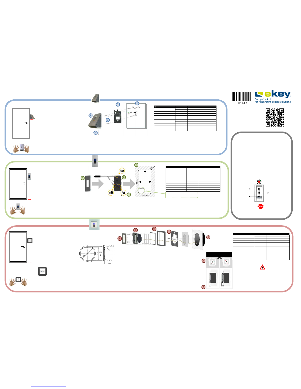
a) Use a gang box according to DIN49072.
Pay attention to the specified installation
height of either 155 cm or 100 cm from
ground level.
The gang box has to stick to the minimum
dimensions as outlined in the drawing above
(DIN49072).
The recommended installation height is
155 cm
from ground level to the lower
edge of the scanner (or higher)!
To safeguard proper operation by the user,
resulting in an acceptable rate of
recognition, pay attention to the specified
installation height!
Alternatively, you can also install the finger
scanner horizontally. The recommended
installation height is
110 cm
then!
Make sure to have enough space on both
sides of the finger scanner to allow proper
operation with all fingers.
Horizon
tal installation
Installation Height
Installation
155 cm
a) Cut out an area of W 39,5 mm H 85 mm D 16 mm in the door pane l or door frame
(1).
b) Use the supplied screws (2x. 2,9 x 19 / 2x 2,9 x 38) for mounting the finger scanner
(2)
. Attention! Do not tighten screws too much; otherwise the hou sing might
get damaged! By tightening the screws, the 3 clamps
(3)
will move outwards securing the finger scanner.
c) Finally, clip the design element
(4)
onto the finger scanner.
For the installation into a solid wall you will require a mounting bracket. P lease contact your ekey installer for further details!
Make sure to have enough space on both
sides of the finger scanner to allow proper
operation with all fingers.
The recommended installation height is
155 cm
from ground level to the lower
edge of the scanner (or higher)!
To safeguard proper operation by the user,
resulting in an acceptable rate of
recognition, pay attention to the specified
installation height!
155 cm
Installation Height
Installation
You might not be able
to level the
finger
scanner and the
design frame with all frames from different producers.
In this case, the ekey FS OM will stick out
on the front side.
The recommended installation height is
135 cm
from ground level to the lower
edge of the scanner (or higher)!
To safeguard proper operation by the user,
resulting in an acceptable rate of
recognition, pay attention to the specified
installation height!
Make sure to have e
nough space on both
sides of the finger scanner to allow proper
operation with all fingers.
135
cm
a) To mount the ekey FS WM 2.0
(1)
, please use the supplied screws and plastic dowels.
(2)
Mark the drill holes on the wall using the mounting bracket
(3)
.
b) Drill two 5 mm wide holes and place the dowels into them. Afterwards, fasten the mounting bracket using the corresponding screws.
To establish the electrical connection, please refer to the wiring p lan.
c) Finally, clip the ekey FS WM 2.0 into the mount ing bracket and fix the scanner tightening the dedicated screw
(4)
.
Installation Height
Wall
-
mounted (WM)
integra (IN)
Outlet mounted (OM)
Finger mould
Sensor
The sensor must not be touched using
a
sharp
object as it could destroy the sensor!!
Cleaning & Maintenance
This installation manual as well ast he information provided on the accompanying DVD is not subject to any
revision. The latest valid version of this document is available under
www.ekey.net.
Subject to optical and technical modifications, any liability for m isprints excluded!
Installation
for ekey Finger Scanner (FS)
Description Unit Value
Power Supply
VAC 8-24
VDC 8-24
Power Input W ca. 1
Temperature Range °C -25 up to +75
Memory Size Fingerprints
home: 99
net: 40/200/2000
Security
FAR 1x 10
-
6
FRR 1,4x 10
-
2
IP class IP 44
Matching Speed S 1-4
Life Span Swipes ca. 10 Mio
Dimensions mm B: 45 H: 81,6 T: 60,3
Technical Data
Spacer and
Design Frame
Insert
Finger Scanner
Bezel
MOUNTING INSTRUCTION
Gang Box according to
DIN49072 for installation in
walls
Dimension Gang Box
Description Unit Value
Power Supply
VAC 8-24
VDC 8-24
Power Input W ca. 1
Temperature Range °C -25 up to +70
Memory Size Fingerprints
home: 99
net: 40/200/2000
Security FAR 1x 10
-
7
IP class
FRR 1,4x 10
-
2
IP
IP33/44 depending on
frames
Matching Speed S 1-4
Life Span Swipes ca.10 Mio
Dimensions mm B: 50,4 H: 50,4 T: 30,1
Technical Data
The LED indicates a dirty sensor by blinking red-green
Bullet point +
LED
Description Unit Value
Power Supply
VAC 8-24
VDC 8-24 (max. 30V)
Power Input W ca. 1
Temperature Range °C -25 up to +70
Memory Size Fingerprints
home: 99
net: 40/200/2000
Security
FAR 1x 10
-
7
FRR 1,4 x 10
-
2
IP class IP 54 (front end)
Matching Speed S 1-4
Life Span Swipes ca. 10 Mio.
Dimensions mm W: 43,6 H: 89 D: 17,3
Technical Data
Opening for cable feed (RJ45)
Fixing Screw
Finger Scanner
Screw
Mounting Bracket
Dowels
Cable
Design Element
Clamps
Finger Scanner
Screw Driver
ID25:
Version: 2, 14.03
.2012
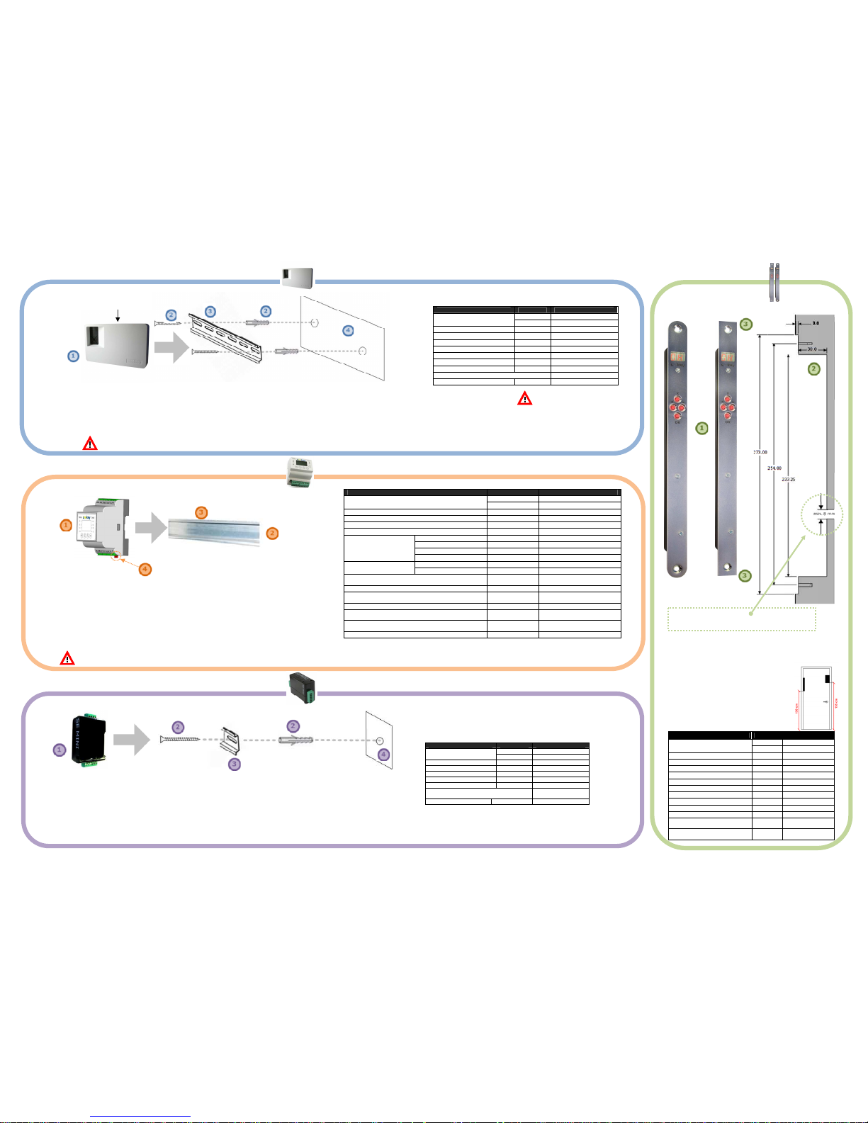
a) To mount the ekey control panel
(1)
, please use the supplied screws and plastic dowels
(2).
Mark the drill holes
(4)
on the wall using the DIN rail
(3).
b) Drill two 5 mm wide holes and place the dowels into them. Afterwards, fasten the DIN rail using the corresponding screws.
c) Finally, clip the ekey CP WM onto the rail.
Alternatively, your ekey CP WM can be installed on the DIN rail (35 mm) in your electrical cabinet.
Installation
Open lid for electric
con
nection
Wall
-
mounted (WM)
integra
Openin
g for cable
feed
(the position of the opening can be higher or lower)
DIN rail mounted (DRM)
Installation
a) A DIN rail according to DIN EN 55022
or
DIN EN 60715 TH35 with 35 mm
is suited best to install the ekey CP
DRM (multi)
(1).(2)
You can therefore install the ekey CP DRM (multi) in your electr ical cabinet.
b) Attach the upper part of the control panel on the DIN rail
(3).
c) Pull the latch
(4)
downward and place the lower part of the control panel on the DI N rail as well. Finally, release
the latch to fasten the control panel.
a) To mount the ekey CP IN
(1)
in the door, please work it according to
template
(2)
. Available milling width: 18, 20 or 24 mm
Pay attention to the control panel’s shape of the forend.
(square / round)
b) To fasten the control panel, please use the
supplied screws.
c) Tighten the screws at the predefined holes at
top and bottom of your ekey CP IN
(3)
.
Description Unit Value
Power Supply
VAC 8-24
VDC 8-24 (max. 30V)
Relay Amount 1 / 2
Relay Switching Capacity VAC (DC) 42 VDC (AC) / 2A
Peak AC VAC (DC) 60
ON Resistor (max.) 0,12
Leakage Current A 1
Boot time ms 1,5
Shut-off time ms 0,5
Temperature Range °C -40 up to + 85
IP class IP 40 (front end)
Digital inputs Amount 1
Maximum voltage on X6 Pin 1
(only applicable for integra)
A 3
Dimensions mm
W: 18/20/24,
H: 272, D: 21
Technical Data
m
ini (mini)
Installation
a) To mount the ekey CP mini
(1)
, please use the supplied screw and plastic dowel.
(2)
Mark the drill hole
(4)
on the wall using the DIN rail
(3)
.
b) Drill a 5 mm wide hole and place the dowel into it.
c) Afterwards, fasten the DIN rail using the corr esponding screw
d) Finally, clip the ekey CP mini onto the rail.
Alternatively, your ekey CP mini can be installed on the DIN rail (35 mm) in your electrical cabinet.
Description Unit Value
Power Supply
VAC 8-24
VDC 8-30
Power Input W ca.1
Relay Amount 1
Relay Switching Capacity 42 VDC / 1 A
Temperature Range °C -20 up to +70
IP class IP 20
Digital input
(only
dry contact configurable!)
1
Dimensions mm W: 25 H: 60 D: 42
Technical Data
for ekey control panels (CP)
ekey control panel for integration into door panels!
Description Unit Value
Power Supply
VAC 8-24
VDC 8-24
Power Input W ca. 1W
Temperature Range °C -20 up to +70
Dimensions 4HP acc. DIN 43880
Interfaces RS485
Relay
max. Switching Voltage 1) VAC / VDC 42
max. Switching Current 1) AAC / ADC 2
Mechanical Life Span Operations 10 Mill.
Electric Life Span1) 2) Operations 100 000
Input 3)
Low kΩ <1
High kΩ >50
IP class IP
20 (to be mounted in the electric
cabinet)
Programming 4 Push Buttons
Display
1 LED for relays (green); 1 LED
for inputs (red), LCD 106x56
max. wiring length of RS485 bus line (CLAMP 1,2)
4)
m 500
max. wiring length of supply line (CLAMP 3,4,5,6)
when used in an industrial area
m 30
max. length of wires for relay and input (CLAMP 7-24)
when used in an industrial area
m 30
Dimensions mm W: 70 (4HP) H: 86 D: 54
Technical Data
1) Ohmic load exclusively
2) When switching inductive and capacitive loads, adequate safety measures should be taken in order to protect the relay contacts (sparks
suppressor). The control panel does not have any built-in spark suppressors.
3) Define low and high, at which resistance between Input 12C and Input1, respectively Input2 are recognized as low or high.
4) When using the recommended cables
Forend
round
cut
Forend square
cut
*
The life span of the relay output decreases furthe
r when switching inductive or capacitive
loads.
If you switch such loads, you have to take precautions on the relay output to avoid flying sparks.
There are no spark extinction elements built-in the ekey control panels!!
Description Un it Value
Power Supply
VAC 9-12
VDC 9-12
Power Input W ca. 1
Relay Amount 1/3
Relay Switching Capacity A 230VAC/ 5A
mech. Relay Life Span Operations 10 Mill.
elec. Relay Life Span * Operations 200.000 at 250V/5A
Temperature Range °C -20 up to +70
IP Class IP 20
Digital Inputs Dimensions mm W: 180 H: 110 D: 39,2
Technical Data
Make sure to
leave
enough space above (for opening) and below
(for electric wiring) the
CP!
Make sure to leave enough space below the CP
(
for electric wiring
)!
 Loading...