

Page 1

USE AND INSTRUCTION MANUAL
USE AND INSTRUCTION MANUALUSE AND INSTRUCTION MANUAL
USE AND INSTRUCTION MANUAL
MOD
MODMOD
MODDDDD.... KF
KF KF
KF 666633330 D
0 D0 D
0 D UD
UDUD
UD –––– KF 733 D UD
KF 733 D UD KF 733 D UD
KF 733 D UD
KF 9
KF 9KF 9
KF 933337777 D
D D
D UD
UDUD
UD –––– KF 966 D AL
KF 966 D ALKF 966 D AL
KF 966 D AL UD
UDUD
UD –––– KF 966 D UD
KF 966 D UD KF 966 D UD
KF 966 D UD
rev.
rev. rev.
rev. 2222
TECNOEKA
TECNOEKATECNOEKA
TECNOEKA S.r.l.
S.r.l. S.r.l.
S.r.l.
Via I. Nievo, n.12/B
Via I. Nievo, n.12/B Via I. Nievo, n.12/B
Via I. Nievo, n.12/B ---- 35012 Camposampiero (Padova) Italy
35012 Camposampiero (Padova) Italy 35012 Camposampiero (Padova) Italy
35012 Camposampiero (Padova) Italy
Tel. +39.049.9300344
Tel. +39.049.9300344 Tel. +39.049.9300344
Tel. +39.049.9300344 –––– +39.049.5791479 Fax +39.049.5794387
+39.049.5791479 Fax +39.049.5794387+39.049.5791479 Fax +39.049.5794387
+39.049.5791479 Fax +39.049.5794387
www.tecnoeka.com
www.tecnoeka.comwww.tecnoeka.com
www.tecnoeka.com E
E E
E----mail:
mail: mail:
mail: info@tecnoeka.com
info@tecnoeka.cominfo@tecnoeka.com
info@tecnoeka.com
Page 2

_ TECNOEKA Srl __________________________________________________________ use and instruction manual _
_ page. 2 ________________________________________________________________________________________
X:\Sgq\PRODOTTI\Fam. 1 - FORNI\FORNO ELETTRICO\LEka\MANUALI D'USO - Forno Elettrico 40 60 90 LEka\Instruction manual KF 630 D UD - KF 733 D UD - KF 937 D UD - KF 966 D AL UD - KF 966 D UD GB rev. 2.doc
Page 3
_ Electric Ovens _ rev. 2 _______________________________________ KF 630 D UD – KF 733 D UD – KF 937 D UD
KF 966 D AL UD – KF 966 D UD _
________________________________________________________________________________________ page. 3 _
Prodotti mirati per Ristorazioni, Pasticcerie,
Prodotti mirati per Ristorazioni, Pasticcerie,Prodotti mirati per Ristorazioni, Pasticcerie,
Prodotti mirati per Ristorazioni, Pasticcerie,
Pane
PanePane
Panetterie e Gastronomie
tterie e Gastronomietterie e Gastronomie
tterie e Gastronomie
TECNOEKA Srl
TECNOEKA SrlTECNOEKA Srl
TECNOEKA Srl
Via I. Nievo, 12/B
35012 Camposampiero (PD)
Tel. +39 049 5791479 - +39 049 9300344
Fax + 39 049 5794387
www.tecnoeka.com – info@tecnoeka.com
CE
DECLARATION OF CONFORMITY
Annexed document II A, of directive 98/37/CE
Annexed document II A, of directive 98/37/CEAnnexed document II A, of directive 98/37/CE
Annexed document II A, of directive 98/37/CE
Manufacturer TECNOEKA Srl
TECNOEKA SrlTECNOEKA Srl
TECNOEKA Srl
Address Via I. Nievo, 12/B
Via I. Nievo, 12/B Via I. Nievo, 12/B
Via I. Nievo, 12/B ---- 35012 Camposampiero (PD)
35012 Camposampiero (PD) 35012 Camposampiero (PD)
35012 Camposampiero (PD)
Type of product Electric ovens
Electric ovensElectric ovens
Electric ovens
Models
KF 630 D UD
KF 630 D UD KF 630 D UD
KF 630 D UD ---- KF 733 D UD
KF 733 D UD KF 733 D UD
KF 733 D UD ---- KF 93
KF 93 KF 93
KF 937 D UD
7 D UD7 D UD
7 D UD
KF 966 D AL UD
KF 966 D AL UDKF 966 D AL UD
KF 966 D AL UD ---- KF 966 D UD
KF 966 D UD KF 966 D UD
KF 966 D UD
TECNOEKA Srl declares that the above mentioned products conform to the safety
regulations under:
CEI EN 60335-1
- Low voltage directive 2006/95/EC
CEI EN 60335-2-42
CEI EN 55014-1
CEI EN 55014-2
CEI EN 61000-3-2
CEI EN 61000-3-3
CEI EN 61000-4-2
CEI EN 61000-4-4
CEI EN 61000-4-5
CEI EN 61000-4-6
- Electromagnetic compatibility Directive 2004/108/EC
CEI EN 61000-4-11
- Machine Directive 98/37/ EC;
- Directive on the general safety of products 2001/95/ EC;
- Directive on the restriction in the use of dangerous substances in
electrical and electronic appliances 2002/95/ EC;
- Directive on waste from electrical and electronic appliances 2002/96/ EC.
Camposampiero, 22/04/2010.
_________________________________
__________________________________________________________________
_________________________________
Signature of a Representative of the Board of directors
Page 4

_ TECNOEKA Srl __________________________________________________________ use and instruction manual _
_ page. 4 ________________________________________________________________________________________
Page 5

_ Electric Ovens _ rev. 2 _______________________________________ KF 630 D UD – KF 733 D UD – KF 937 D UD
KF 966 D AL UD – KF 966 D UD _
________________________________________________________________________________________ page. 5 _
Index
IndexIndex
Index
1.
1.1.
1. Technical service
Technical serviceTechnical service
Technical service
2.
2.2.
2. General warnings
General warningsGeneral warnings
General warnings
3.
3.3.
3. Technical specifications
Technical specificationsTechnical specifications
Technical specifications
4.
4.4.
4. Instructions for the installer
Instructions for the installerInstructions for the installer
Instructions for the installer
5.
5.5.
5. Use instructions (for the user
Use instructions (for the userUse instructions (for the user
Use instructions (for the user))))
6.
6.6.
6. Residual risks (for the user)
Residual risks (for the user)Residual risks (for the user)
Residual risks (for the user)
7.
7.7.
7. How to use the control panel
How to use the control panelHow to use the control panel
How to use the control panel
8.
8.8.
8. Ignition
IgnitionIgnition
Ignition
9.
9.9.
9. Switch
SwitchSwitch
Switch----off
offoff
off
10.
10.10.
10. Operation mode
Operation modeOperation mode
Operation mode
11.
11.11.
11. Cooking cycle ON/OFF
Cooking cycle ON/OFFCooking cycle ON/OFF
Cooking cycle ON/OFF
12.
12.12.
12. Displaying / changing parameters with the cooking cycle ON
Displaying / changing parameters with the cooking cycle ONDisplaying / changing parameters with the cooking cycle ON
Displaying / changing parameters with the cooking cycle ON
13.
13.13.
13. Delayed start to the cooking cycle
Delayed start to the cooking cycleDelayed start to the cooking cycle
Delayed start to the cooking cycle
14.
14.14.
14. “Programmed” mode
“Programmed” mode“Programmed” mode
“Programmed” mode
15.
15.15.
15. Saving
Saving Saving
Saving cooking programs
cooking programscooking programs
cooking programs
16.
16.16.
16. Cooking with a saved program
Cooking with a saved programCooking with a saved program
Cooking with a saved program
17.
17.17.
17. Manual humidifying
Manual humidifyingManual humidifying
Manual humidifying
18.
18.18.
18. Door device
Door deviceDoor device
Door device
19.
19.19.
19. Black
Black Black
Black –––– out
out out
out
20.
20.20.
20. Oven cooking
Oven cookingOven cooking
Oven cooking
21.
21.21.
21. Routine cleaning and maintenance
Routine cleaning and maintenance Routine cleaning and maintenance
Routine cleaning and maintenance
22.
22.22.
22. Possible faults
Possible faultsPossible faults
Possible faults
23.
23.23.
23. Fuse replacement
Fuse replacementFuse replacement
Fuse replacement
24.
24.24.
24. Technical
Technical Technical
Technical assistance
assistanceassistance
assistance
25.
25.25.
25. Informations to the consumers
Informations to the consumersInformations to the consumers
Informations to the consumers
26.
26.26.
26. Wiring layouts
Wiring layoutsWiring layouts
Wiring layouts
27.
27.27.
27. The Warranty
The WarrantyThe Warranty
The Warranty
Page 6
_ TECNOEKA Srl __________________________________________________________ use and instruction manual _
_ page. 6 ________________________________________________________________________________________
1.
1. 1.
1. Technical service
Technical serviceTechnical service
Technical service
A technical check-up once or twice a year helps prolong the life of the appliance and
guarantees better operation. Make sure that assistance is carried out solely and exclusively by
qualified personnel. For any spare parts orders or for any information about the appliance,
always mention the serial number and model (data indicated on the "technical data" plate at
the rear of the oven).
2.
2. 2.
2. General warnings
General warningsGeneral warnings
General warnings
Very important!: keep this instruction book together with the appliance for future
consultation.
These warnings were drafted for your safety and for that of others. Please read them
carefully before installing or using the appliance:
- If, on receipt of the goods, the packaging
packagingpackaging
packaging is damaged, write the following on the delivery
note: “I REVERSE THE RIGHT TO CONTROL THE GOODS
I REVERSE THE RIGHT TO CONTROL THE GOODSI REVERSE THE RIGHT TO CONTROL THE GOODS
I REVERSE THE RIGHT TO CONTROL THE GOODS”, specify the damage and get
the driver to sign in acceptance; send a claim in writing to the seller within 4 calendar
days from the date of receipt. No claim shall be accepted after such period.
- The warehouse inside temperature must not be lower than -9°C; otherwise, the
thermostat (regulation and safety thermostat) control devices of the machine will be
damaged. Failure to observe this prohibition invalidates any responsibility of the
manufacturer of the machine.
- The appliance is intended for professional use and must be utilised by qualified personnel
trained to use it.
- Any modification which may be necessary on the electrical system to enable installation
of the appliance, must be carried out solely by competent personnel.
- It is dangerous to modify or attempt to modify the characteristics of this appliance.
- Never clean the appliance with direct water jets, because, if any water enters, it could
limit the machine's safety .
- Before doing any maintenance or cleaning jobs, disconnect the appliance from the
electrical mains and allow it to cool.
- When the tilting door is wide open, do not put anything on the surface, because the
door hinges could be irreparably damaged.
- Do not attempt to carry out the periodic controls or any repairs by yourself. Contact the
nearest Service Centre and use only original spare parts.
N.B.:
N.B.: N.B.:
N.B.: Improper or incorrect use and failure to observe the installation instructions shall release
Improper or incorrect use and failure to observe the installation instructions shall release Improper or incorrect use and failure to observe the installation instructions shall release
Improper or incorrect use and failure to observe the installation instructions shall release
the manufacture from all responsibility.
the manufacture from all responsibility.the manufacture from all responsibility.
the manufacture from all responsibility. In thi
In thiIn thi
In this connection, the directives in the
s connection, the directives in the s connection, the directives in the
s connection, the directives in the
"POSITIONING" paragraph must be strictly observed.
"POSITIONING" paragraph must be strictly observed."POSITIONING" paragraph must be strictly observed.
"POSITIONING" paragraph must be strictly observed.
3.
3. 3.
3. Technical specifications
Technical specificationsTechnical specifications
Technical specifications
KF 630 D UD
KF 630 D UDKF 630 D UD
KF 630 D UD KF 733 D UD
KF 733 D UDKF 733 D UD
KF 733 D UD KF 937 D UD
KF 937 D UDKF 937 D UD
KF 937 D UD
KF 966 D AL
KF 966 D AL KF 966 D AL
KF 966 D AL UD
UDUD
UD
KF 966 D UD
KF 966 D UDKF 966 D UD
KF 966 D UD
Dimensions of appliance
Dimensions of applianceDimensions of appliance
Dimensions of appliance LxDxH(mm) 590x590x595
590x590x595590x590x595
590x590x595 670x625x555
670x625x555670x625x555
670x625x555 790x665x505
790x665x505790x665x505
790x665x505 790x6
790x6790x6
790x665x635
65x63565x635
65x635
Weight
Weight Weight
Weight (Kg) 33339999 40
4040
40 45
4545
45 55555555
Cooking chamber Vol.
Cooking chamber Vol. Cooking chamber Vol.
Cooking chamber Vol. (dm3=lt) 55
5555
55 60
6060
60 60
6060
60 91
9191
91
Convection heating element
Convection heating element Convection heating element
Convection heating element (kW) 2,7
2,72,7
2,7 3,0
3,03,0
3,0 3,5
3,53,5
3,5 3,0
3,03,0
3,0
Max. absorbed power
Max. absorbed powerMax. absorbed power
Max. absorbed power
(kW) 2,9
2,92,9
2,9 3,2
3,23,2
3,2 3,
3,3,
3,7777 6,4
6,46,4
6,4
Power supply voltage
Power supply voltage Power supply voltage
Power supply voltage (V)
(50
(50(50
(50/60
/60/60
/60Hz)
Hz) Hz)
Hz) AC 220/230 V
AC 220/230 V AC 220/230 V
AC 220/230 V
380/400 2N
380/400 2N380/400 2N
380/400 2N
(50
(50(50
(50/60
/60/60
/60Hz)
Hz)Hz)
Hz)
Power
PowerPower
Power cable diameter
cable diameter cable diameter
cable diameter 3x1,5 mm
3x1,5 mm3x1,5 mm
3x1,5 mm
2222
4x2,5
4x2,5 4x2,5
4x2,5 mm
mmmm
mm
2222
Type of cable
Type of cableType of cable
Type of cable H07RN
H07RNH07RN
H07RN----FFFF
Class
ClassClass
Class I (against electric shocks)
I (against electric shocks)I (against electric shocks)
I (against electric shocks)
The noise level of the appliance in operation is below 70 dB (A).
The noise level of the appliance in operation is below 70 dB (A).The noise level of the appliance in operation is below 70 dB (A).
The noise level of the appliance in operation is below 70 dB (A).
The "technical data" plate is positioned on the rear panel of the appliance.
The "technical data" plate is positioned on the rear panel of the appliance.The "technical data" plate is positioned on the rear panel of the appliance.
The "technical data" plate is positioned on the rear panel of the appliance.
Page 7

_ Electric Ovens _ rev. 2 _______________________________________ KF 630 D UD – KF 733 D UD – KF 937 D UD
KF 966 D AL UD – KF 966 D UD _
________________________________________________________________________________________ page. 7 _
4.
4. 4.
4. Instructions fo
Instructions foInstructions fo
Instructions for the installer
r the installerr the installer
r the installer
The following instructions are aimed at the qualified installer, to ensure that he carries out
the installation, adjustment and maintenance operations as correctly as possible and according
to current legal regulations. Any operation must be performed with electrical power cut to the
appliance.
Before using the appliance, carefully remove the special adhesive film protecting the parts in
stainless steel. Do not leave any glue residues on the surfaces. If necessary, remove them at
once, with an appropriate solvent.
Fitting the feet
Fitting the feetFitting the feet
Fitting the feet - The feet are inside the appliance and must be secured on the four threaded
holes on the base. If necessary, the height of the feet can be adjusted by screwing or
unscrewing.
Positioning
PositioningPositioning
Positioning - Position the appliance perfectly horizontally on a table or similar support (the
table or support must be at least 85 cm above the floor). Position it at a distance of not less
than 10 cm from the side and rear walls, to enable natural ventilating air to circulate freely
around it.
The appliance is not suitable for embedding and for grouped positioning with other identical
appliances.
Electrical connection
Electrical connectionElectrical connection
Electrical connection - The appliance must be connected to the electrical mains according to
current legal regulations. Before making the connection, make sure of the following:
- the voltage and frequency values of the power supply system match the values on the
"technical data" plate affixed on the appliance;
- the limiting valve and the system are able to support the appliance's load (see the
"technical data" plate);
- the power supply system has an adequate earth connection according to current legal
the power supply system has an adequate earth connection according to current legal the power supply system has an adequate earth connection according to current legal
the power supply system has an adequate earth connection according to current legal
regulations;
regulations;regulations;
regulations;
- a omnipolar switch with minimum between-contacts aperture of 3 mm, sized to the load
and conforming to current legal regulations, is fitted between the appliance and the
mains in the direct connection to the mains;
- the omnipolar switch used for connection is easy to reach when the appliance is
installed;
- the yellow/green earth wire is not interrupted by the switch;
the yellow/green earth wire is not interrupted by the switch;the yellow/green earth wire is not interrupted by the switch;
the yellow/green earth wire is not interrupted by the switch;
- the power supply, when the appliance is operating, must not deviate from the rated
voltage value by ±10%;
- make sure that after inserting the power supply cord into the terminal block it does not
come into contact with any of the cooking range's hot parts.
Connection to the water mains
Connection to the water mainsConnection to the water mains
Connection to the water mains - (for ovens predisposed to humidifier solenoid-valve)
The appliance must be fed with softened drinking water, with pressure in the range from
100 to 200 kPa (1.0 - 2.0 bar). Water must have hardness from 0.5°F to 3°F (it is suggstible to
use a softener as to avoid the malfunction of the fan, the breakage of the heating element and
to reduce the formation of lime inside the cooking chamber). Connection to the water mains
should be made through the threaded 3/4" solenoid-valve on the rear (on the bottom) of the
appliance, fitting in between a mechanical filter and an on/off tap (before you connect the filter,
allow a certain quantity of water to flow out in order to drain any waste from the pipe).
Connection to water tank
Connection to water tank Connection to water tank
Connection to water tank ---- (for ovens predisposed to water pump)
To replace electrovalve with water pump (in ovens with optional predisposition to pump), follow
the steps below listed (image 1):
1) Remove back cover from oven.
2) Disconnect wiring cables from electrovalve.
3) Disconnect water tube (3) from electrovalve, pressing e keeping pressed the edge of
black linking (quick insertion).
4)
Remove the electrovalve unscrewing the screw that fix it to oven’s frame.
Page 8

_ TECNOEKA Srl __________________________________________________________ use and instruction manual _
_ page. 8 ________________________________________________________________________________________
5) Fix the pump (1) to the frame with the appropriate support (2) and the two screws (4)
included.
6) Connect the cables previously disconnected from electrovalve to pump.
7) Connect the tube previously disconnected from electrovalve to pump’s linking.
8) Connect the tube (6) with filter and ballast (included in “Pump kit”) to pump’s apron (7).
9) Replace back cover.
Fig.1
Fig.1Fig.1
Fig.1
Warning:
Warning:Warning:
Warning:
To avoid limestone buildup into the cooking chamber, we suggest to fill the water tank with
decalcified water.
Check water level in the tank before activating the pump and during its functioning. If pump
Check water level in the tank before activating the pump and during its functioning. If pump Check water level in the tank before activating the pump and during its functioning. If pump
Check water level in the tank before activating the pump and during its functioning. If pump
works without water in the tank, what occurs is ab
works without water in the tank, what occurs is abworks without water in the tank, what occurs is ab
works without water in the tank, what occurs is abnormal noise at first and then its breakage
normal noise at first and then its breakagenormal noise at first and then its breakage
normal noise at first and then its breakage
....
Connecting the power cable
Connecting the power cableConnecting the power cable
Connecting the power cable::::
––––
Mod.
Mod. Mod.
Mod. KF 6
KF 6KF 6
KF 633330 D
0 D 0 D
0 D UD
UDUD
UD
–––– The terminal board is on the rear panel of the appliance. Open the
terminal board cover by obtaining leverage with a screwdriver on the two side fins. Loosen the
cable gripper screw and allow the cable to pass through it. Arrange the conductors so that the
earth conductor is the last to detach from its terminal if the cable goes into a state of faulty
traction. Connect the phase
phasephase
phase conductor to the terminal marked with the letter "L"
"L""L"
"L", the neutral
neutral neutral
neutral
conductor to the terminal marked with the letter "N"
"N""N"
"N" and the earth
earthearth
earth conductor to the terminal
marked with the symbol .
Tighten the ring-nut of the cable gripper and close the terminal board cover.
––––
Modd.
Modd. Modd.
Modd. KF 733 D UD
KF 733 D UD KF 733 D UD
KF 733 D UD –––– KF
KF KF
KF 999937
3737
37 D
D D
D UD
UDUD
UD
–––– To access the terminal board, just remove the
appliance's rear side-panel. Loosen the cable gripper and allow the cable to pass through it.
Arrange the conductors so that the earth conductor is the last to detach from its terminal if the
cable goes into a state of faulty traction. Connect the phase
phasephase
phase conductor to the terminal marked
“L1”
“L1”“L1”
“L1”, connecting the neutral
neutral neutral
neutral conductor to the terminal marked "N"
"N""N"
"N" and the earth
earthearth
earth conductor to
the terminal marked with the symbol .
Tighten the cable gripper and re-fit the rear side-panel of the appliance.
–
Mod
Mod Mod
Moddddd.
. .
. KF 966 D AL
KF 966 D ALKF 966 D AL
KF 966 D AL UD
UDUD
UD –––– KF 966 D UD
KF 966 D UD KF 966 D UD
KF 966 D UD
–––– To access the terminal board, just remove the
appliance's rear side-panel. Loosen the cable gripper and allow the cable to pass through it.
Arrange the conductors so that the earth conductor is the last to detach from its terminal if the
cable goes into a state of faulty traction. Connect the phase
phasephase
phase conductors to the terminals marked
“L1”
“L1”“L1”
“L1” and “L2”
“L2”“L2”
“L2”, connecting the neutral
neutral neutral
neutral conductor to the terminal marked "N"
"N""N"
"N" and the earth
earthearth
earth
conductor to the terminal marked with the symbol
according to the following lay-out:
Page 9

_ Electric Ovens _ rev. 2 _______________________________________ KF 630 D UD – KF 733 D UD – KF 937 D UD
KF 966 D AL UD – KF 966 D UD _
________________________________________________________________________________________ page. 9 _
(this electrical connection lay-out is located near the power supply terminal board ). Tighten the
cable gripper and re-fit the rear side-panel of the appliance.
Any appliance must be connected to an equipotential system
equipotential systemequipotential system
equipotential system whose efficiency must first be
checked according to current legal regulations.
This connection must be made between different appliances by using the appropriate
terminal marked with the symbol . The equipotential conductor must have a minimum
diameter of 10 mm2 The equipotential terminal is at the rear of the appliance.
Safety thermal breaker
Safety thermal breakerSafety thermal breaker
Safety thermal breaker - The appliance is supplied with a manually resetting thermal breaker
to protect against excessive, dangerous temperatures which could be accidentally generated
inside. If it is tripped, the device cuts off the power supply to the appliance.
The device is located on the back of the unit and is identified by a suitable label. The reset
button can be activated after unscrewing the black plastic cover and letting the oven cool
down.
5.
5. 5.
5. Use instructions (for the user)
Use instructions (for the user)Use instructions (for the user)
Use instructions (for the user)
For first use, we advise you to let the appliance to run load-free for 30/40 minutes at a
temperature of 200°C. In this way, any unpleasant smells due to thermal insulation and residual
work grease are eliminated.
This appliance must be used solely for the purpose for which it was expressly designed, i.e.
cooking foods in the oven. Any other use is considered unsuitable.
The appliance can be used: for all oven cooking of deserts, pizzas, meat, fish, vegetables, as
well as for re-conditioning cooled and frozen foods.
When placing food in the cooking compartment, leave a space of at least 40 mm between
pans in order not to over-obstruct air circulation.
Do not use pans with higher than necessary edges: edges are barriers which prevent the
circulation of hot air (for cooking of bread and pastry; do not use pans with borders higher than
20mm, avoid that products into the pan get in contact).
Warm up the oven before every cooking operation (set a temperature 30°C higher than
cooking temperature) to obtain maximum uniformity.
Do not salt foods in the cooking compartment.
6.
6. 6.
6. Residual risks (for the user)
Residual risks (for the user)Residual risks (for the user)
Residual risks (for the user)
After a cooking operation, open the door cautiously, to avoid a violent outflow of heat which
could cause burns.
While the oven is in operation, pay attention to the possible hot zones (marked on the
appliance) of its external surfaces.
Place the machine on a bench or similar support, at a height of at least 85 cm from the floor.
The bench or support must be able to support the weight of the machine and house it
correctly.
The appliance contains electrical parts and must never be washed with a jet of water or
steam.
The appliance is electrically connected: before attempting any cleaning operation, cut power
to the appliance.
Do not use the door handle to move the appliance (the glass panel may break).
When the tilting door is wide open, there is the risk that things could be placed on the
surface with the risk of irreparably damaging the door hinges.
Page 10

_ TECNOEKA Srl __________________________________________________________ use and instruction manual _
_ page. 10 ________________________________________________________________________________________
7.
7. 7.
7. How to use the control panel
How to use the control panelHow to use the control panel
How to use the control panel
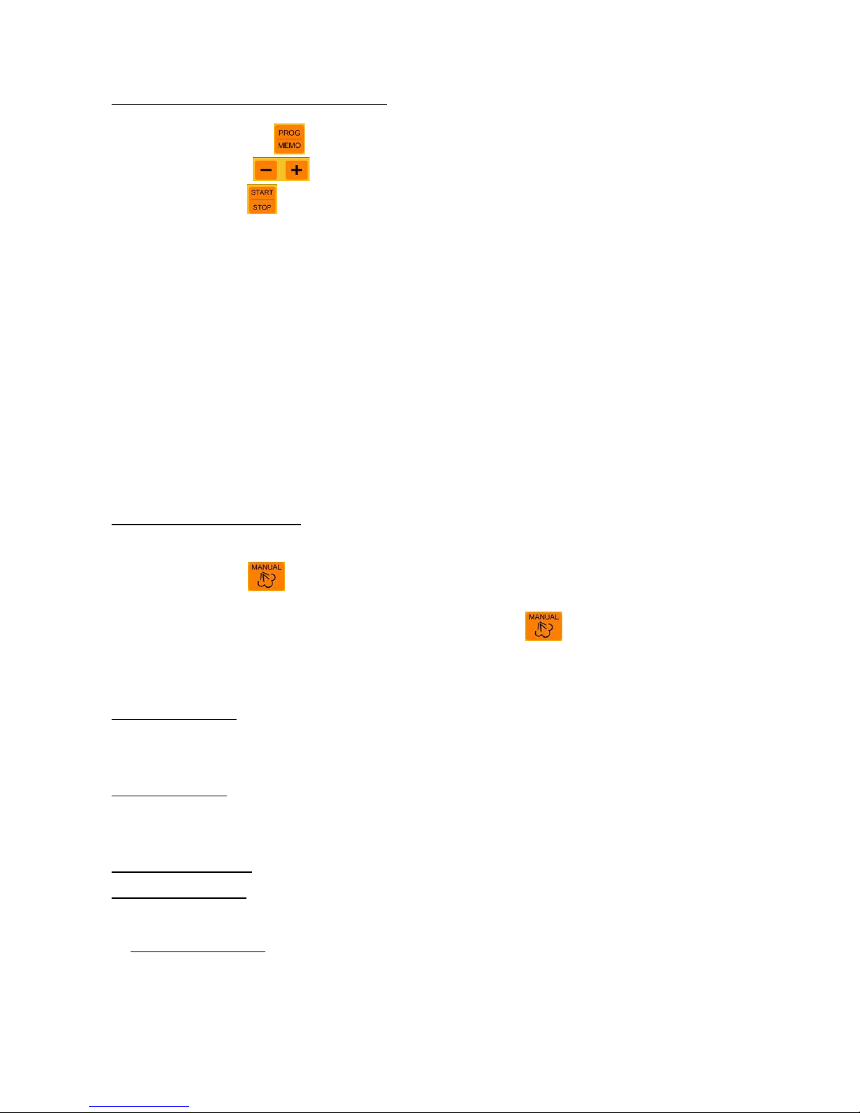
Control Panel symbol legend:
Control Panel symbol legend:Control Panel symbol legend:
Control Panel symbol legend:
1)
1)1)
1)
Parameter on signal LED
6)
6)6)
6)
Parameter value decrease button
2)
2)2)
2)
Cooking parameter selection button
7)
7)7)
7)
Parameter value increase button
3)
3)3)
3)
Step on signal LED
8)
8)8)
8)
Cooking program select/save button
4)
4)4)
4)
Cooking step selection button
9)
9)9)
9)
Manual humidifying button
5)
5)5)
5)
Parameter display
10)
10)10)
10)
START/STOP button
8. Ignition
8. Ignition8. Ignition
8. Ignition
The control panel (digital) automatically turns on as soon as the oven is electrically powered.
The lights in the cooking chamber turn on. “0.00” appears on the display to indicate time
(expressed in hours and minutes) and the time led turns on in the parameter field (symbol ).
The phase 1 led turns on in the “phase” field (set to receive cooking parameters).
9. Switch
9. Switch9. Switch
9. Switch----off
offoff
off
The control panel automatically turns off10 minutes after the cooking cycle ends (in “manual"
mode or in “automatic” mode whether switched-off automatically or by pressing the
button) without any button being pressed.
The lights in the cooking chamber turn off, the display and operating function leds turn off.
Only the button led remains on.
To restart the control panel, simply press the button.
10. Operation mode
10. Operation mode10. Operation mode
10. Operation mode
The cooking cycle can be run in “manual” or “programmed” mode which can be divided in 4
steps. TIME/TEMPERATURE/HUMIDITY cooking parameters can be set for each step.
MANUAL MODE
To select cooking parameters (TIME/TEMPERATURE/HUMIDITY), press the button the led
for the selected parameter turns on each time the button is pressed. At least cooking time and
temperature parameters must be set for the cooking cycle to start.
• To select cooking cycle steps (1 – 2 – 3 – 4), press the button the led relevant
to the selected step turns on each time the button is pressed. The led relevant to the current
step blinks during the cooking cycle.
• To set or change the selected parameter, press buttons .
Press button to increase the parameter. - Press button to decrease the parameter.
1111
2222
3333
4444
5555
6666
7777
8888
9999
1111
0000
Page 11

_ Electric Ovens _ rev. 2 _______________________________________ KF 630 D UD – KF 733 D UD – KF 937 D UD
KF 966 D AL UD – KF 966 D UD _
________________________________________________________________________________________ page. 11 _
• The time parameter (symbol ) can be set from 0 hours and 01 minutes to 9
hours and 59 minutes. If “INF” or “HLD” appear on the display, this means that the timer is
excluded. The oven operates continuously until manually turned off with the button.
When “INF” appears on the display (only displayed for step 1), steps 2 - 3 - 4 are disabled (leds
off).
When “HLD” appears on the display (only displayed for step 4), this means that the cooking
cycle, after terminating the previous steps, continues without the timer and with the parameters
set for phase 4. (The cooking cycle is switched off by pressing the button). This operation
lets the user keep food “warm” (at the end of the cooking cycle) for the desired amount of time.
The temperature parameter (symbol ) can be set from 50° C to 270° C.
The humidity parameter (symbol ) can be set from 0 to 100 (continuous humidity).
11. Cooking cycle ON/OFF
11. Cooking cycle ON/OFF11. Cooking cycle ON/OFF
11. Cooking cycle ON/OFF
The cooking cycle starts and stops by pressing the button. The resistance, motor and water
solenoid valve are switched off at the end of the cooking cycle. The buzzer sounds for 30
seconds and “0.00” blinks on the display. Temperature/humidity parameter settings for the last
cycle step remain set.
If an “extra-time” is set during the next 30 seconds, the oven automatically restarts and cooking
continues with the temperature and humidity parameters for the last step used. When “extra
time” has elapsed, the cooking cycle ends.
If the 30 seconds elapse or the cooking cycle is interrupted by pressing the button, all set
parameters are reset and the oven readies for new cooking cycle settings.
11112222. Displaying / changing parameters with the cooking cycle ON
. Displaying / changing parameters with the cooking cycle ON. Displaying / changing parameters with the cooking cycle ON
. Displaying / changing parameters with the cooking cycle ON
When the cooking cycle is on, parameters can be displayed by pressing the button and
values can be changed (keys ) in each step ( button) in the cooking cycle.
Several seconds after the last change (for any of the four steps) operating step parameters are
displayed (led blinks on current step).
If the
“Time” parameter is selected
The value set for the selected step (led on symbol ) is displayed for 4 seconds alternated by
the remaining total (COUNT DOWN) for the rest of the other steps for 4 seconds (led blinks on
symbol ).
“Temperature” parameter
The value set for the selected step (led on symbol ) is displayed for 4 seconds alternated by
the value read in the cooking chamber for 4 seconds (led blinks on symbol ).
“Humidity” parameter
The set value is displayed for the selected step (fixed led on symbol ).
Page 12

_ TECNOEKA Srl __________________________________________________________ use and instruction manual _
_ page. 12 ________________________________________________________________________________________
13. Delayed start to the cook
13. Delayed start to the cook13. Delayed start to the cook
13. Delayed start to the cooking cycle
ing cycleing cycle
ing cycle
To delay the start for the cooking cycle, proceed as follows:
• Set the required parameters for each phase in the cooking cycle, following the
instructions in the paragraph “OPERATING METHOD” (paragraph 10).
• Press the key until all the signal leds go out on the control panel. The message
“0.00” appears on the display.
• Press the / keys and set the required “DELAY TIME” on the display (maximum 9
hours and 59 minutes).
• Press the key to activate the delayed start.
The led on the key starts flashing to show that the COUNTDOWN has started shown on
the display. The DELAY TIME can be changed at any moment during the COUNTDOWN by
pressing the / keys.
When the DELAY TIME is up, the cooking cycle will start automatically.
To zero the DELAY TIME, just press the key; the display will show the operating
parameters than can be changed. Press the again to continue the cooking cycle;
otherwise a delayed start for the cooking cycle can be reset by proceeding as above.
N.B.: in case of BLACKOUT or power failure during the COUNTDOWN, the programmed
delay for the cooking cycle is cancelled and all the relative set parameters are zeroed.
A delayed start to the cooking cycle is only possible in MANUAL MODE. It cannot be included
in a programmed cooking cycle.
11114444. “Programmed” mode
. “Programmed” mode. “Programmed” mode
. “Programmed” mode
Up to 99 cooking programs (cycles) can be saved. Each program can include 1 or more cooking
steps (up to 4).
11115555. Saving cooking programs
. Saving cooking programs. Saving cooking programs
. Saving cooking programs
Follow the steps below to save a cooking program:
- press the button (led on) “P01" appears on the display.
- Press buttons and select the required program number (up to P99).
- Set the relevant cooking cycle parameters following the same procedure used for
“manual” mode.
- Press and hold down the button for at least 5 seconds: the program is successfully
saved with the saved program number blinks on the display.
To cancel a saved program, simply replace it with a new program (with the same number)
where new parameters are set for the new cooking cycle. The new program must be saved
by pressing the button.
Page 13
_ Electric Ovens _ rev. 2 _______________________________________ KF 630 D UD – KF 733 D UD – KF 937 D UD
KF 966 D AL UD – KF 966 D UD _
________________________________________________________________________________________ page. 13 _
11116666. Cooking with a saved program
. Cooking with a saved program. Cooking with a saved program
. Cooking with a saved program
Follow the steps below to run a saved cooking program:
- press the button “P01" appears on the display.
- Press buttons and select the required program number
- Press button .
“P – H” appears on the display (cooking chamber “preheating” function).
The oven operates until it reaches a temperature equal to the value set for step 1 (programmed
cycle) increased by 30°C.
When the preheating temperature is reached, “P – H” blinks on the display and the buzzer
sounds.
At this point, open the oven door, introduce food to be cooked and close the door. the buzzer
turns off and the programmed cooking cycle starts.
N.B.: the “preheating” function is available (automatically started) only in "programmed"
cooking modes.
When the oven is operating in “programmed” mode, set parameters can be displayed in the
same way as with “manual” mode.
For the user’s convenience, set parameters can be changed during oven operations in
“programmed” mode.
At the end of the programmed cooking cycle, changed parameters are automatically “RESET”
and return to the values initially saved in the program.
11117777. Manual humidifying
. Manual humidifying. Manual humidifying
. Manual humidifying
Humidity can be produced in the cooking chamber (water solenoid valve on or activation of
water pump) at any time in the cooking cycle (in both “manual” and “programmed" mode) by
pressing the button (led on).
Continuous humidity as long as the button is pressed.
If an automatic humidifying cycle is in progress, press button (water solenoid valve on or
activation of water pump) to interrupt it. Release the automatic humidifying cycle button to
resume.
11118888. Door device
. Door device. Door device
. Door device
The device stops oven operations (stops the cooking cycle) whenever the door is opened. The
cooking cycle resumes where it left off when the door is closed.
11119999. Black
. Black . Black
. Black ---- out
outout
out
When power returns after a black-out, the oven automatically resumes operations and the
cooking cycle resumes from where it left off.
20
2020
20.
. .
. Oven cooking
Oven cookingOven cooking
Oven cooking
Cooking techniques
Cooking techniquesCooking techniques
Cooking techniques
There are two different cooking techniques with this oven: convection and convection +
humidification.
Convection cooking
Convection cookingConvection cooking
Convection cooking - Heat is transferred to the foods by pre-heated air, forced to circulate by
in the cooking chamber. The heat quickly and uniformly reaches all parts of the chamber,
enabling simultaneous cooking of different types of food (providing they have the same cooking
temperature), placed on the shelves without mixing tastes and smells. Convection cooking is
particularly convenient for rapid de-freezing, and for sterilising preserves and drying mushrooms
and fruit.
Page 14

_ TECNOEKA Srl __________________________________________________________ use and instruction manual _
_ page. 14 ________________________________________________________________________________________
Cooking Co
Cooking CoCooking Co
Cooking Convection + humidification
nvection + humidificationnvection + humidification
nvection + humidification - The fact of using a hot-moist climate inside the
cooking chamber with variable temperature and moisture levels, is the most convenient and
efficient way of cooking: cooking times are reduced, the surface of the foods remains soft and
does not form a crust, there is little weight loss and the fatty mass is reduced.
22221111.
. .
. Routine cleaning and maintenance
Routine cleaning and maintenanceRoutine cleaning and maintenance
Routine cleaning and maintenance
(WARNING:
(WARNING:(WARNING:
(WARNING: Cut power to the appliance before every operation)
Cut power to the appliance before every operation)Cut power to the appliance before every operation)
Cut power to the appliance before every operation)
General cleaning
General cleaningGeneral cleaning
General cleaning - Clean the oven when it is cold. Wash enamelled parts with lukewarm
water and soap, do not use abrasive products, steel wool, or acids, which could ruin them. To
clean the steel parts, do not use products containing chlorine (sodium hypochlorite, hydrochloric
acid, etc) even if diluted. Use specific off-the-shelf products or a little hot vinegar. Rinse
thoroughly with water and dry with a soft cloth. Clean the glass door of the oven with hot
water only, and do not use rough cloths. Do not allow foods (especially acid foods such as salt,
vinegar, lemon, etc) to stagnate on the stainless steel parts, because they could deteriorate. Do
not wash the appliance with direct jets of water, because if water enters, this could limit the
appliance's safety. Do not use corrosive substances (e.g. hydrochloric acid) to clean the oven' s
support bench.
Cleaning the oven
Cleaning the ovenCleaning the oven
Cleaning the oven - It is good practice to clean the oven interior at the end of every day of
duty. In this way it will be easier to remove cooking residues, preventing them from burning
when the oven is next used. Clean it accurately with hot water and soap or with the appropriate
off-the-shelf products.
Cleaning the oven door
Cleaning the oven doorCleaning the oven door
Cleaning the oven door - To clean the oven door thoroughly, proceed as follows:
- fully open the door;
- insert the equipped plugs in the “A” holes on the hinges (Fig. 2);
- lift the door gently and withdraw it (Fig. 3);
- put back the door in the initial position by operating inverserly.
Fig.
Fig. Fig.
Fig. 2222
Fig.
Fig. Fig.
Fig. 3333
Fig.
Fig. Fig.
Fig. 4444
Replacing oven lamp
Replacing oven lampReplacing oven lamp
Replacing oven lamp - Electrically switch off the appliance; unscrew the protective glass cap
with the corresponding rings for airproofing (Fig. 4); unscrew the lamp and replace it with
another lamp suitable for high temperatures (300°C), with the following characteristics:
- Voltage 230/240 V
- Power 15 W
- Fitting E 14
Refit the glass cap with the corresponding rings for airproofing and power up the appliance.
Page 15

_ Electric Ovens _ rev. 2 _______________________________________ KF 630 D UD – KF 733 D UD – KF 937 D UD
KF 966 D AL UD – KF 966 D UD _
________________________________________________________________________________________ page. 15 _
22222222. Possible faults
. Possible faults. Possible faults
. Possible faults
Type of fault
Type of faultType of fault
Type of fault Cause
CauseCause
Cause Corrective action
Corrective actionCorrective action
Corrective action
- Incorrect electric connections to the mains - Check the mains connection
-
No mains voltage
-
Restore mains voltage
-
Thermal break safety device tripped
-
Reset the thermal break safety
device
Control panel
completely off (the
oven does not work)
-
Electronic card protection fuse (control panel)
burnt
-
Change the fuse
- Door open or ajar - Close the door
Cooking cycle set and
push button
pressed: the oven
does not work
-
Damaged door switch device
-
Contact a qualified technician to
repair the sensor
- Incorrect connection to water mains
- Connection of non-conforming pump
- Check the connection to water
mains (electrovalve) or the
connection of pump
- Cut-off cock closed (electrovalve)
-
Tank without water (pump)
- Check the cut-off cock
-
Check water level into the tank
-
Blocked water inlet filter
-
Clean the filter
Humidity production
in cooking chamber
on: No water flows
from the pipes
(on the fans)
-
Electrovalve or pump water entrance damaged
-
Contact a qualified technician to
repair the solenoid
- Seal not fitted correctly - Check the seal fitting
-
Damaged seal
-
Contact a qualified technician to
repair the seal
Door closed: water /
vapour comes out of
the seal
-
Handle mechanism loosened (lateral opening
door)
-
Contact a qualified technician to
repair the prong
- One of the motors is blocked or turns slowly (If
the oven has two motors)
- Contact a qualified technician to
repair the motor
-
The motors do not go into reverse
-
Contact a qualified technician to
repair the motor
The oven does not
cook evenly
-
Heating element not powered or is damaged
-
Contact a qualified technician to
repair the element
- Damaged lamp - Change the lamp
Lighting lamp in the
cooking chamber does
not work
-
Light bulb “unscrewed”
-
Make sure the light bulb is fully
screwed-in.
- Breaking in the connection between the cooking
chamber probe (electronic card) and the control
panel
- Check the connection to the
control panel
“ER1”
“ER1”“ER1”
“ER1” appears on the
display
-
Damaged cooking chamber probe
-
Contact a qualified technician to
repair the probe
Page 16

_ TECNOEKA Srl __________________________________________________________ use and instruction manual _
_ page. 16 ________________________________________________________________________________________
22223333.
. .
. Fuse replacement
Fuse replacementFuse replacement
Fuse replacement
If the appliance is powered but the display and leds are off on the control panel (electronic
board) it may mean that the control panel fuse is blown. To access the fuse, remove the control
panel. Slightly press the fuse box cap and, holding down, rotate it slightly counter-clockwise until
it removes. After replace the fuse with one that has the same specifications, close the fuse box
cap rotating it in the opposite direction.
22224444.
. .
. Technical
Technical Technical
Technical assistance
assistanceassistance
assistance
Before leaving the factory, the appliance was completely regulated and tested by expert
specialised personnel to guarantee the best operating results.
All repairs and settings must be performed with utmost care and attention, respecting
national safety regulations in force. Always contact your retailer or our nearest Service Centre,
giving details of the problem, the appliance model and the serial number (on the rating plate on
the rear panel).
For any maintenance the user can contact Tecnoeka by calling the telephone numbers on the
cover or going to www.tecnoeka.com
www.tecnoeka.comwww.tecnoeka.com
www.tecnoeka.com.....
22225555.
. .
. Informations to the consumers
Informations to the consumersInformations to the consumers
Informations to the consumers
Further to Directive 2002/96/EC, the symbol of the crossed rubbish skip on
the appliance means that at the end of its life, the product must be
disposed of separately from the other rubbish. The user must hand the
appliance to a specialised waste collection centre for electric and electronic
equipment.
The separate collection of the rubbish and subsequent treatment, recovery and disposal help to
produce other equipment using recycled materials, reducing the negative effects on the
environment and public health, which would be caused by incorrect management of the
rubbish.
Should the user dispose of the product abusively, administrative sanctions would be applied
pursuant.
Page 17

_ Electric Ovens _ rev. 2 _______________________________________ KF 630 D UD – KF 733 D UD – KF 937 D UD
KF 966 D AL UD – KF 966 D UD _
________________________________________________________________________________________ page. 17 _
22226666.
. .
. Wiring layouts
Wiring layoutsWiring layouts
Wiring layouts
MOD
MODMOD
MODDDDD. KF 6
. KF 6. KF 6
. KF 633330 D
0 D 0 D
0 D UD
UDUD
UD –––– KF
KF KF
KF 733
733733
733 D
D D
D UD
UD UD
UD –––– KF 937 D UD
KF 937 D UD KF 937 D UD
KF 937 D UD
Key
KeyKey
Key
M Power terminal board
T1 Safety thermostat
MI Door microswitch
SD Electronic card
EV Humidifier solenoid-valve
B Contactor coil
L Oven lighting lamp
R Circular heating-element
V Oven motorised ventilator
C Capacitor
Page 18
_ TECNOEKA Srl __________________________________________________________ use and instruction manual _
_ page. 18 ________________________________________________________________________________________
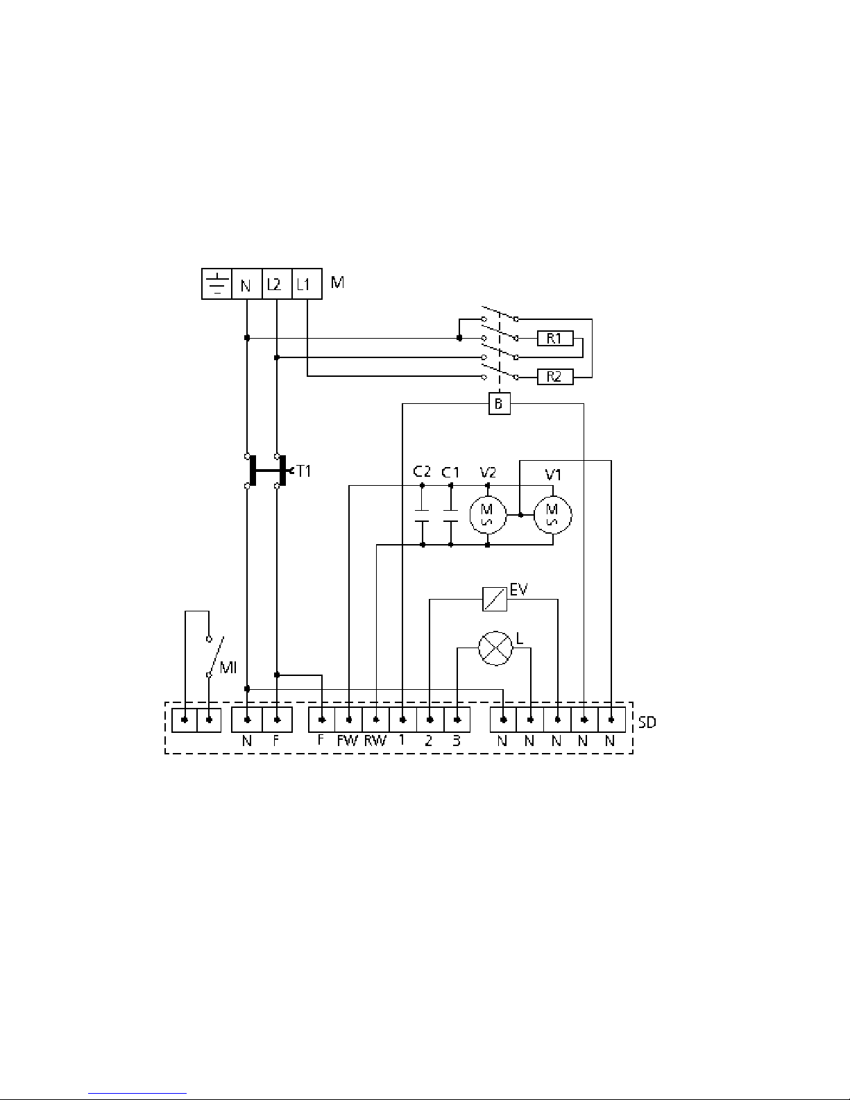
MOD
MODMOD
MODDDDD. KF
. KF . KF
. KF 966
966966
966 D
D D
D AL
ALAL
AL UD
UDUD
UD –––– KF 966 D UD
KF 966 D UD KF 966 D UD
KF 966 D UD
Key
KeyKey
Key
M Power terminal board
T1 Safety thermostat
MI Door microswitch
SD Electronic card
EV Humidifier solenoid-valve
B Contactor coil
L Oven lighting lamp
R1-R2 Circular heating-elements
V1-V2 Radial motoventilators
C1-C2 Capacitors
Page 19

_ Electric Ovens _ rev. 2 _______________________________________ KF 630 D UD – KF 733 D UD – KF 937 D UD
KF 966 D AL UD – KF 966 D UD _
________________________________________________________________________________________ page. 19 _
22227777.
. .
. The Warranty
The WarrantyThe Warranty
The Warranty
Your appliance is covered by warranty. The seller will replace or repair (and his decision will be final),
free of charge for the customer, only those parts that are defective due to a manufacturing fault on
condition that, under penalty of forfeiture:
− for domestic equipment, the customer notifies the fault within two months from the date when
he/she discovered it and anyway within 2 years form the date of purchase;
− for professional equipment, the customer notifies the fault within 8 days from the date when
he/she discovered it and anyway within 12 months from the date of purchase,
by registered letter with acknowledgement of receipt and enclosing the invoice or receipt proving the
purchase.
Apart from the case when the customer cannot produce the invoice or receipt proving the purchase or
when the above-mentioned terms are not complied with, the warranty is expressly excluded
warranty is expressly excluded warranty is expressly excluded
warranty is expressly excluded in the
following cases:
1) faults or breakage caused by the transport;
2) wrong or incorrect installation of the product (for instance because of insufficient draught of the
flue or exhausts) in light of the instructions given in the user’s handbook supplied with the
product;
3) inadequate or abnormal electrical, hydraulic and/or gas supplies;
4) carelessness, negligence or incompetence in using the product in light of the instructions given in
the user’s handbook supplied with the product;
5) use of the product for uses different from the one for which it was built or anyway in a manner
not compliant with the instructions given in the user’s handbook supplied with the product;
6) tampering with the product;
7) adjustments and/or maintenance and/or repairs carried out by unauthorised personnel and/or
with non original spare parts;
8) inadequate or careless maintenance of the product in contrast with the user’s handbook supplied
with the product;
9) damages caused by fire, natural disasters and accident as well as by any cause not attributable to
TECNOEKA SRL.
The warranty explicitly excludes
The warranty explicitly excludesThe warranty explicitly excludes
The warranty explicitly excludes: varnished or enamelled parts, knobs, handles, movable or removable
plastic parts, bulbs, glass parts, refractories and any accessories.
TECNOEKA SRL cannot be held responsible for any damages, either direct or indirect, caused by the
product breaking down or following its non-use.
Any repairs carried out during the warranty do not cause said warranty to be extended or renewed.
Nobody is authorised to modify the terms and conditions of the warranty or to issue new verbal or
written warranties.
The warranty is valid only for appliances installed in the European Union.
The warranty is valid only for appliances installed in the European Union.The warranty is valid only for appliances installed in the European Union.
The warranty is valid only for appliances installed in the European Union.
Any dispute shall be settled by the competent Court in Padua.
Warning for the
Warning for the Warning for the
Warning for the Buyer:
Buyer:Buyer:
Buyer:
1. the cooking appliance is designed only for cooking purposes while the heating appliance is
designed only for heating domestic environments;
2. TECNOEKA S.r.l. does not install the appliances; the seller shall be responsible for any installation
carried out;
3. TECNOEKA S.r.l. cannot be held responsible for any damages, either direct or indirect, to people,
pets or property caused by the appliance breaking down or following its non-use.
The Manufacturer cannot be held responsible for any inaccuracies due to misprints or mistakes in
copying in this handbook. The Manufacturer reserves the right to modify the products as he deems fit,
also in the interest of the user, without affecting the vital characteristics of functionality and safety.
 Loading...