

eka EKF 711UD–EKF 664UD–EKF 664 UD-HTEKF 664 UD/003, EKF 664 UD/003, EKF 616 U, EKF 616 UD-HT Use And Instruction Manual Use And Instruction Manual
Page 1
USE AND INSTRUCTION MANUAL
USE AND INSTRUCTION MANUALUSE AND INSTRUCTION MANUAL
USE AND INSTRUCTION MANUAL
MOD
MODMOD
MODDDDD.... EEEEKF
KF KF
KF 711
711711
711 UD
UDUD
UD –––– EEEEKF
KF KF
KF 664
664664
664 UD
UDUD
UD –––– EKF
EKF EKF
EKF 664 UD
664 UD664 UD
664 UD----HT
HT HT
HT
EKF 664 UD/003
EKF 664 UD/003EKF 664 UD/003
EKF 664 UD/003 –––– EKF
EKF EKF
EKF 616 UD
616 UD616 UD
616 UD –––– EKF
EKF EKF
EKF 616 UD
616 UD616 UD
616 UD----HT
HTHT
HT
rev.
rev.rev.
rev. 2222
TECNOEKA S.r.l.
Via Marco Polo, n.11 - 35010 Borgoricco (Padova) Italy
Tel. +39.049.9300344 – +39.049.5791479 Fax 049.5794387
www.tecnoeka.com E-mail: info@tecnoeka.com
Page 2

TECNOEKA Srl ______________________________________________________________ use and instruction manual
page 2 __________________________________________________________________________________________
X:\Sgq\PRODOTTI\1 - FORNI\FORNO ELETTRICO\LEka\MANUALI D'USO - Forno Elettrico 40 60 90 -
LEka\Lingua Inglese\NUOVA GAMMA EF\Instruction manual EKF 711 UD - EKF 664 UD (-HT) - EKF 664
UD_003 - EKF 616 UD (-HT) - GB - rev. 2.doc
Page 3
Electric Oven rev. 2 ____________________EKF 711 UD – EKF 664 UD (-HT) – EKF 664 UD/003 – EKF 616 UD (-HT)
___________________________________________________________________________________________ page 3
CE
DECLARATION OF CONFORMITY
Annexed document II A, of directive 2006/42/EC
Annexed document II A, of directive 2006/42/ECAnnexed document II A, of directive 2006/42/EC
Annexed document II A, of directive 2006/42/EC
Manufacturer’s name TECNOEKA Srl
TECNOEKA SrlTECNOEKA Srl
TECNOEKA Srl
Manufacturer’s address Via
Via Via
Via Marco Polo
Marco PoloMarco Polo
Marco Polo, 1
, 1, 1
, 11111 ---- 3501
35013501
35010000 Borgoricco
BorgoriccoBorgoricco
Borgoricco (PD)
(PD)(PD)
(PD)
Manager’s name of technical file Minotto Lorenzo
Minotto LorenzoMinotto Lorenzo
Minotto Lorenzo
Manager’s address of technical file Via
Via Via
Via Marco Polo
Marco PoloMarco Polo
Marco Polo, 1
, 1, 1
, 11111 ---- 3501
35013501
35010000 Borgoricco
BorgoriccoBorgoricco
Borgoricco (PD)
(PD)(PD)
(PD)
Type of product Electronic oven
Electronic ovenElectronic oven
Electronic oven
Purpose of the product Cooking fo
Cooking foCooking fo
Cooking food
odod
od
Model EEEEKF
KF KF
KF 711 UD
711 UD 711 UD
711 UD –––– EKF 664 UD
EKF 664 UDEKF 664 UD
EKF 664 UD –––– EKF 664 UD
EKF 664 UDEKF 664 UD
EKF 664 UD----HT
HTHT
HT
EKF 664 UD/003
EKF 664 UD/003EKF 664 UD/003
EKF 664 UD/003 –––– EKF 616 UD
EKF 616 UDEKF 616 UD
EKF 616 UD –––– EKF
EKF EKF
EKF 616 UD
616 UD616 UD
616 UD----HT
HTHT
HT
TECNOEKA Srl declares that the mentioned above products meet the following safety
regulations:
Low voltage directive 2006/95/CE
Electromagnetic compatibility Directive 2004/108/CE.
TECNOEKA Srl declares that the mentioned above products meet the following harmonised
standards:
CEI EN 60335-1 ; CEI EN 60335-2-42
CEI EN 55014-1 ; CEI EN 61000-3-2 ; CEI EN 61000-3-3 ; CEI EN 62233
TECNOEKA Srl declares that the mentioned above products meet the following directives:
Machine Directive 2006/42/CE;
Directive on the general safety of products 2001/95/CE;
Directive on the restriction in the use of dangerous substances in electrical and electronic
appliances 2011/65/CE;
Directive on waste from electrical and electronic appliances 2002/96/CE (RAEE).
TECNOEKA Srl declares that the mentioned above products meet the
CE 1907/2006 (REACH) Regulation
Borgoricco, 16/03/2015.
________________________________
________________________________________________________________
________________________________
Signature of a Representative of the Board of directors
(CRISTINA LORA)
Page 4

TECNOEKA Srl ______________________________________________________________ use and instruction manual
page 4 __________________________________________________________________________________________
Index
IndexIndex
Index
1. Technical service
2. General warnings
3. Technical specifications
4. Instructions for the installer
5. Use instructions (for the user)
6. Residual risks (for the user)
7. How to use the control panel
8. Oven cooking
9. Cleaning
10. Maintenance
11. Technical service
12. Information to the consumers
13. Wiring layout
14. The Warranty
Page 5
Electric Oven rev. 2 ____________________EKF 711 UD – EKF 664 UD (-HT) – EKF 664 UD/003 – EKF 616 UD (-HT)
___________________________________________________________________________________________ page 5
1111.
. .
. Technical service
Technical serviceTechnical service
Technical service
A technical check-up once or twice a year helps prolong the life of the appliance and
guarantees better operation.
Make sure that assistance is carried out solely and exclusively by qualified personnel.
For any spare parts orders or for any information about the appliance, always mention the serial
number and model (data indicated on the "technical data" plate at the rear of the oven).
2.
2. 2.
2. General warnings
General warningsGeneral warnings
General warnings
Very important!: keep this instruction book together with the appliance for future consultation.
These warnings were drafted for your safety and for that of others. Please read them carefully
before installing or using the appliance:
- If, on receipt of the goods, the packaging
packagingpackaging
packaging is damaged, write the following on the delivery
note: “I REVERSE THE RIGHT TO CONTROL THE GOODS
I REVERSE THE RIGHT TO CONTROL THE GOODSI REVERSE THE RIGHT TO CONTROL THE GOODS
I REVERSE THE RIGHT TO CONTROL THE GOODS”, specify the damage and get
the driver to sign in acceptance; send a claim in writing to the seller within 4 calendar
days from the date of receipt. No claim shall be accepted after such period.
- The appliance is intended for professional use and must be utilised by qualified personnel
trained to use it.
- Any modification which may be necessary on the electrical system to enable installation
of the appliance, must be carried out solely by competent personnel.
- It is dangerous to modify or attempt to modify the characteristics of this appliance.
- Never clean the appliance with direct water jets, because, if any water enters, it could
limit the machine's safety .
- Before doing any maintenance or cleaning jobs, disconnect the appliance from the
electrical mains and allow it to cool.
- Do not attempt to carry out the periodic controls or any repairs by yourself. Contact the
nearest Service Centre and use only original spare parts.
N.B.:
N.B.:N.B.:
N.B.: Improper or incorrect use and failure to observe the installation instructions shall release
Improper or incorrect use and failure to observe the installation instructions shall release Improper or incorrect use and failure to observe the installation instructions shall release
Improper or incorrect use and failure to observe the installation instructions shall release
the manufacture from all responsibility.
the manufacture from all responsibility.the manufacture from all responsibility.
the manufacture from all responsibility. In this connection, the directives in the "POSITIONING"
In this connection, the directives in the "POSITIONING" In this connection, the directives in the "POSITIONING"
In this connection, the directives in the "POSITIONING"
paragr
paragrparagr
paragraph must be strictly observed.
aph must be strictly observed.aph must be strictly observed.
aph must be strictly observed.
3.
3. 3.
3. Technical specifications
Technical specificationsTechnical specifications
Technical specifications
Models
ModelsModels
Models
EKF 711 UD
– EKF 664 UD
(-
HT)
EKF 616 UD (-HT)
EKF 664 UD/003
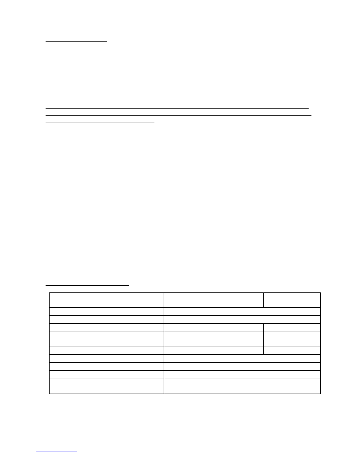
Dimensions of appliance LxDxH (mm)
Dimensions of appliance LxDxH (mm)Dimensions of appliance LxDxH (mm)
Dimensions of appliance LxDxH (mm)
935x930x825
Weight (Kg)
Weight (Kg)Weight (Kg)
Weight (Kg)
96,4
Convection heating element (kW)
Convection heating element (kW)Convection heating element (kW)
Convection heating element (kW)
4
(x2) 3 (x2)
Max. absorbed power (kW)
Max. absorbed power (kW)Max. absorbed power (kW)
Max. absorbed power (kW)
8,4 6,4
Power supply voltage (V)
Power supply voltage (V)Power supply voltage (V)
Power supply voltage (V)
AC 400V 3N (50Hz)
230 V (50Hz)
Power cable diameter
Power cable diameterPower cable diameter
Power cable diameter
5x2,5 mm
2
3x4 mm2
Type of cable
Type of cableType of cable
Type of cable
H07RN
-F
Connecting electric cable
Connecting electric cableConnecting electric cable
Connecting electric cable
Tipo Y
Class
ClassClass
Class
I
Degree of protection against humidity
Degree of protection against humidityDegree of protection against humidity
Degree of protection against humidity
IPX3
Water pressure
Water pressure Water pressure
Water pressure
(kPa)
100-200
TTTThe noise level of the appliance in operation is below 70 dB (A).
he noise level of the appliance in operation is below 70 dB (A).he noise level of the appliance in operation is below 70 dB (A).
he noise level of the appliance in operation is below 70 dB (A).
The "technical data" plate is positioned on the rear panel of the appliance.
The "technical data" plate is positioned on the rear panel of the appliance.The "technical data" plate is positioned on the rear panel of the appliance.
The "technical data" plate is positioned on the rear panel of the appliance.
Page 6

TECNOEKA Srl ______________________________________________________________ use and instruction manual
page 6 __________________________________________________________________________________________
4.
4. 4.
4. Instructions for the installer
Instructions for the installerInstructions for the installer
Instructions for the installer
The following instructions are aimed at the qualified installer, to ensure that he carries out the
installation, adjustment and maintenance operations as correctly as possible and according to
current legal regulations. Any operation must be performed with electrical power cut to the
appliance. Before using the appliance, carefully remove the special adhesive film protecting the
parts in stainless steel. Do not leave any glue residues on the surfaces. If necessary, remove
them at once, with an appropriate solvent.
Positioning
PositioningPositioning
Positioning - Position the appliance perfectly horizontally on a table or similar support (the table
or support must be at least 85 cm above the floor). Position it at a distance of not less than 10
cm from the side and rear walls, to enable natural ventilating air to circulate freely around it.
The appliance is ventilated through specific openings on the metal walls of the outer housing ,
and ensures efficiency and long-life. For this reason it is strictly forbidden to obstruct these
ventilation openings, even partially or for short periods. Failure to observe this specific
Failure to observe this specific Failure to observe this specific
Failure to observe this specific
prohibition releases the manufacturer of the appliance from all responsibility and immediately
prohibition releases the manufacturer of the appliance from all responsibility and immediately prohibition releases the manufacturer of the appliance from all responsibility and immediately
prohibition releases the manufacturer of the appliance from all responsibility and immediately
voids any guarantee rights for the said appliance,
voids any guarantee rights for the said appliance,voids any guarantee rights for the said appliance,
voids any guarantee rights for the said appliance, because its constructive conformity has been
voluntarily compromised. Furthermore, the appliance is not suitable for embedding and for
grouped positioning with other identical appliances.
Electrical connection
Electrical connectionElectrical connection
Electrical connection - The appliance must be connected to the electrical mains according to
current legal regulations. Before making the connection, make sure of the following:
- the voltage and frequency values of the power supply system match the values on the
"technical data" plate affixed on the appliance;
- the limiting valve and the system are able to support the appliance's load (see the
"technical data" plate);
- the power sup
the power supthe power sup
the power supply system has an adequate earth connection according to current legal
ply system has an adequate earth connection according to current legal ply system has an adequate earth connection according to current legal
ply system has an adequate earth connection according to current legal
regulations;
regulations;regulations;
regulations;
- a omnipolar switch with minimum between-contacts aperture of the overvoltage
category III (4000 V), sized to the load and conforming to current legal regulations, is
fitted between the appliance and the mains in the direct connection to the mains;
- the omnipolar switch used for connection is easy to reach when the appliance is
installed;
- the yellow/green earth wire is not interrupted by the switch;
the yellow/green earth wire is not interrupted by the switch;the yellow/green earth wire is not interrupted by the switch;
the yellow/green earth wire is not interrupted by the switch;
- the power supply, when the appliance is operating, must not deviate from the rated
voltage value by ±10%.
- make sure that after inserting the power supply cord into the terminal block it does not
come into contact with any of the cooking range's hot parts.
- if the supply cable is dama
if the supply cable is damaif the supply cable is dama
if the supply cable is damaged then it must be replaced by the manufacturer or by your
ged then it must be replaced by the manufacturer or by your ged then it must be replaced by the manufacturer or by your
ged then it must be replaced by the manufacturer or by your
technical support or by a qualified person to avoid any risk
technical support or by a qualified person to avoid any risktechnical support or by a qualified person to avoid any risk
technical support or by a qualified person to avoid any risk
Connection to the water mains
Connection to the water mainsConnection to the water mains
Connection to the water mains - The appliance must be fed with softened drinking water, with
hardness from 0.5°F to 5°F (it is obligatory to use a softener to reduce the formation of lime
inside the cooking chamber) and pressure in the range from 150 to 250 kPa (1.5 - 2.5 bar).
Connection to the water mains should be made through the threaded 3/4" solenoid-valve on
the rear of the appliance, fitting in between a mechanical filter and an on/off tap (before you
connect the filter, allow a certain quantity of water to flow out in order to drain any waste from
the pipe).
Page 7

Electric Oven rev. 2 ____________________EKF 711 UD – EKF 664 UD (-HT) – EKF 664 UD/003 – EKF 616 UD (-HT)
___________________________________________________________________________________________ page 7
Water drainage
Water drainageWater drainage
Water drainage
A drain pipe (see Fig. 1) comes out from the rear of the appliance, to drain the oven cavity. This
pipe must be connected up to a pipe made to resist steam temperatures (90°C-100°C) with an
internal diameter of 30 mm (DN 30). To prevent choking, it is best to use a rigid pipe and make
sure there are no "elbow" bends anywhere along the drain line. Furthermore, the drain line
must slope down (minimum slope 5%) along its full length (the length in question is from the
appliance's drain pipe to the drain point and must not exceed 2 metres). The drain line must run
into an open floor drain (Fig.2). In addition, there must be a free air gap of at least 25 mm
(distance between the drain line coming from the appliance and the funnel on the drain
standpipe). Whatever the case, in order to comply with current hygiene standards, the line
connected to the appliance's drain pipe must not come into direct contact with the drain point.
It is advisable to include a suitable trap in the line connecting the appliance's drain outlet to the
grey water waste system, thus stopping the steam coming back out of the drain.
FIG.
FIG. FIG.
FIG. 1111 FIG.
FIG. FIG.
FIG. 2222
Connecting the power cable
Connecting the power cableConnecting the power cable
Connecting the power cable (for modd. EKF 711 UD – EKF 664 UD(-HT) – EKF 616 UD(-HT)) - To
reach the power terminal board remove the left side of the appliance. Loosen the cable-clamp
on the back (at the bottom) of the appliance and pass the cable through up to near to the
terminal board. Locate the leads against the terminal board so that the earth lead is the last to
detach from its terminal in the event of reverse pulling. Connect the 3 phase
phase phase
phase leads to the
terminals marked “1” “2”
“1” “2”“1” “2”
“1” “2” and “3”
“3”“3”
“3”, the neutral
neutral neutral
neutral lead to the terminal marked “4”
“4”“4”
“4” or “5”
“5”“5”
“5” and
the earth
earth earth
earth lead to the terminal marked as shown in the following layout:
(this electrical connection lay-out is located near the power supply terminal board ). Tighten the
cable gripper and re-fit the left side-panel of the appliance.
The appliance must be connected to an equipotential system
equipotential systemequipotential system
equipotential system whose efficiency must first be
checked according to current legal regulations.
This connection must be made between different appliances by using the appropriate terminal
marked with the symbol . The equipotential conductor must have a minimum diameter of 2,5
mm
2
The equipotential terminal is at the rear of the appliance.
Page 8

TECNOEKA Srl ______________________________________________________________ use and instruction manual
page 8 __________________________________________________________________________________________
Connecting th
Connecting thConnecting th
Connecting the power cable
e power cablee power cable
e power cable (for mod. EKF 664 UD/003)- To reach the power terminal board
remove the left side of the appliance. Loosen the cable-clamp on the back (at the bottom) of
the appliance and pass the cable through up to near to the terminal board. Locate the leads
against the terminal board so that the earth lead is the last to detach from its terminal in the
event of reverse pulling. Connect the phase
phase phase
phase lead to the terminal marked ““““L”
L”L”
L”, the neutral
neutral neutral
neutral lead to
the terminal marked “N”
“N”“N”
“N” and the earth
earth earth
earth lead to the terminal marked . Tighten the cable
gripper and re-fit the left side-panel of the appliance.
The appliance must be connected to an equipotential system
equipotential systemequipotential system
equipotential system whose efficiency must first be
checked according to current legal regulations.
This connection must be made between different appliances by using the appropriate terminal
marked with the symbol . The equipotential conductor must have a minimum diameter of 2,5
mm2 The equipotential terminal is at the rear of the appliance.
Safety ther
Safety therSafety ther
Safety thermal breaker
mal breakermal breaker
mal breaker - The appliance has a manually reset safety thermal breaker. It protects
against excessive dangerous over-temperatures which could be accidentally generated inside the
appliance. If the device is tripped, it interrupts electrical power to the appliance and thus
prevents it from operating. To access this device, remove the left side-panel of the appliance.
5.
5. 5.
5. Use instructions (for the user)
Use instructions (for the user)Use instructions (for the user)
Use instructions (for the user)
This appliance is not intended for use by persons (including children) with reduced phycal,
sensory or mental capabilities, or lack of experience and knowledge. Unless they have
beengiven supervision or instruction concerning use of appliance by a person responsible for
their safety. Children should be supervised to ensure that they do not play with the appliance.
For first use, we advise you to let the appliance to run load-free at maximum temperature for
about one hour. In this way, any unpleasant smells due to thermal insulation and residual work
grease are eliminated. This appliance must be used solely for the purpose for which it was
expressly designed, i.e. cooking foods in the oven. Any other use is considered unsuitable.
The appliance can be used: for all oven cooking of deserts, pizzas, meat, fish, vegetables, as
well as for gratinating, and for re-conditioning cooled and frozen foods. When placing food in
the cooking compartment, leave a space of at least 40 mm between pans in order not to overobstruct air circulation. Do not use pans with higher than necessary edges: edges are barriers
which prevent the circulation of hot air. Warm up the oven before every cooking operation to
obtain maximum uniformity. Do not salt foods in the cooking compartment.
6.
6. 6.
6. Residual risks (for the user)
Residual risks (for the user)Residual risks (for the user)
Residual risks (for the user)
After a cooking operation, open the door cautiously, to avoid a violent outflow of heat which
could cause burns. While the oven is in operation, pay attention to the hot zones (marked on
the appliance) of its external surfaces. Place the machine on a bench or similar support, at a
height of at least 85 cm from the floor. The bench or support must be able to support the
weight of the machine and house it correctly. The appliance contains electrical parts and must
never be washed with a jet of water or steam. The appliance is electrically connected: before
attempting any cleaning operation, cut power to the appliance. To prevent incorrect connection
of the appliance, the relevant electrical and water connections are marked by identification
plates. If the internal glass panel of the door has to be cleaned, it must be dismantled with the
help of a second operator: one operator supports the glass panel, while the other unscrews its
securing screws.
Page 9

Electric Oven rev. 2 ____________________EKF 711 UD – EKF 664 UD (-HT) – EKF 664 UD/003 – EKF 616 UD (-HT)
___________________________________________________________________________________________ page 9
7.
7. 7.
7. How to use the control panel
How to use the control panelHow to use the control panel
How to use the control panel
1. "End of cooking" programming knob
2. Control thermostat knob
3. Automatic humidifier knob
4. "End of cooking" programmer indicator
light
5. Control thermostat indicator light
6. Automatic humidifier indicator light
1
2
3
4
5
6
Page 10

TECNOEKA Srl ______________________________________________________________ use and instruction manual
page 10 __________________________________________________________________________________________
Fig. 3 Fig. 4
Fig. 5
Programming cooking time
Programming cooking timeProgramming cooking time
Programming cooking time - To run the oven, turn the programmer knob (Fig. 3) in line with
symbol (continuous operation) or in line with the selected cooking time (up to 120 minutes).
In the second case, end of cooking is signalled by the oven switching OFF automatically.
Programming cooking temperature
Programming cooking temperatureProgramming cooking temperature
Programming cooking temperature - Turn the knob of the adjustment thermostat (Fig. 4) in line
with the temperature selected for cooking.
Programming vapour quantity
Programming vapour quantityProgramming vapour quantity
Programming vapour quantity - To generate vapour while the oven is in operation (cooking
compartment hot), turn the knob of the automatic humidifier (Fig. 5) in line with the required
value (from 1 to 5). If you turn the knob to position • (OFF) the humidifier will stop operating.
Remember
RememberRemember
Remember
-
If you turn the knob to positions “1” to “4”, the humidifier operates by generating vapour
“1” to “4”, the humidifier operates by generating vapour “1” to “4”, the humidifier operates by generating vapour
“1” to “4”, the humidifier operates by generating vapour
(water is introduced into the cooking compartment) at automatically adjus
at automatically adjusat automatically adjus
at automatically adjusted, cyclically
ted, cyclically ted, cyclically
ted, cyclically
repeated time intervals
repeated time intervalsrepeated time intervals
repeated time intervals (The higher the number the higher the humidifier operating time and
thus a higher quantity of vapour is produced).
-
If you turn the knob to position "5", automatic control of the humidifier is disabled
"5", automatic control of the humidifier is disabled "5", automatic control of the humidifier is disabled
"5", automatic control of the humidifier is disabled - it now
operates by continuously introducing water into the cooking compartment (continuous
production of vapour).
-
Before beginning to run the automatic humidifier, stabilise the temperature inside the
cooking compartment at a value of at least 110°C, order to optimise vapour production.
"End of cooking" programmer indicator light
"End of cooking" programmer indicator light"End of cooking" programmer indicator light
"End of cooking" programmer indicator light - The programmer green indicator light indicate
that the oven is operating and that cooking time is active.
Control thermostat indicator light
Control thermostat indicator lightControl thermostat indicator light
Control thermostat indicator light - The control thermostat orange indicator light goes OFF
whenever the programmed temperature is reached inside the cooking compartment. It lights up
again when the thermostat is tripped to re-establish this temperature.
Automatic humidifier indicator light
Automatic humidifier indicator lightAutomatic humidifier indicator light
Automatic humidifier indicator light - The orange indicator light of the automatic humidifier
indicates that the water solenoid-valve is operating and, therefore, vapour is being produced in
the cooking compartment.
Oven internal light
Oven internal lightOven internal light
Oven internal light - The light is always on when the oven is operating.
To switch off the oven
To switch off the ovenTo switch off the oven
To switch off the oven - Turn OFF the knobs of the "end of cooking" programmer and of the
thermostat. When you have finished using the oven, shut off the water ON/OFF tap upstream of
the appliance and cut out electric power.
8.
8. 8.
8. Oven cooking
Oven cookingOven cooking
Oven cooking
For cooking, before putting food in, warm up the oven to the required temperature. When the
oven reaches the temperature, put the food in and check cooking time. Switch off the oven 5
minutes before the theoretical time in order to recover stored heat.
Convection cooking (dry heat)
Convection cooking (dry heat)Convection cooking (dry heat)
Convection cooking (dry heat) - Operate the oven and turn the thermo state knob to the
desired temperature.
Convection cooking + steam (dry heat + wet heat)
Convection cooking + steam (dry heat + wet heat)Convection cooking + steam (dry heat + wet heat)
Convection cooking + steam (dry heat + wet heat) - Operate the oven and turn the thermo
state knob to the desired temperature and the humidifier know the desired steam quantity.
De freezing
De freezingDe freezing
De freezing - Operate the oven and turn the thermo state knob and the humidifier knob in
correspondence of position OFF (•).
Page 11

Electric Oven rev. 2 ____________________EKF 711 UD – EKF 664 UD (-HT) – EKF 664 UD/003 – EKF 616 UD (-HT)
___________________________________________________________________________________________ page 11
9.
9. 9.
9. Cleaning (WARNING:
Cleaning (WARNING:Cleaning (WARNING:
Cleaning (WARNING: Cut power to the appliance before every operation)
Cut power to the appliance before every operation)Cut power to the appliance before every operation)
Cut power to the appliance before every operation)
General cleaning
General cleaningGeneral cleaning
General cleaning - Clean the oven when it is cold. Wash enamelled parts with lukewarm water
and soap, do not use abrasive products, steel wool, or acids, which could ruin them. To clean
the steel parts, do not use products containing chlorine (sodium hypochlorite, hydrochloric acid,
etc) even if diluted. Use specific off-the-shelf products or a little hot vinegar. Rinse thoroughly
with water and dry with a soft cloth. Clean the glass door of the oven with hot water only, and
do not use rough cloths. Do not allow foods (especially acid foods such as salt, vinegar, lemon,
etc) to stagnate on the stainless steel parts, because they could deteriorate. Do not wash the
appliance with direct jets of water, because if water enters, this could limit the appliance's
safety. Do not use corrosive substances (e.g. hydrochloric acid) to clean the oven' s support
bench.
Cleaning the oven
Cleaning the ovenCleaning the oven
Cleaning the oven - It is good practice to clean the oven interior at the end of every day of duty.
In this way it will be easier to remove cooking residues, preventing them from burning when the
oven is next used. Clean it accurately with hot water and soap or with the appropriate off-theshelf products.
Cleaning the door
Cleaning the doorCleaning the door
Cleaning the door - The glass panel of the door facing inwards toward cooking compartment
can be cleaned with the same type of degreasing product used to clean the compartment.
Otherwise, you can use normal glass cleaning product (non toxic). A common glass detergent
can be used also to clean the glass panel of the door facing outward. In all cases, you may just
use tepid soapy water. After rinsing, thoroughly dry the glass surface with a soft cloth. If
opaque sections form between the two glass panels of the door, they can be eliminated after
dismantling the internal glass panel.
Cleaning the fans
Cleaning the fansCleaning the fans
Cleaning the fans - The fans must be periodically cleaned with specific anti-lime scale products.
All the parts must be carefully cleaned, removing all lime scale deposits. To have access to the
fans remove the fan casing after removing the screws that fix it to the cooking chamber. When
cleaning is complete, replace the casing and screws.
Cleaning the door seal
Cleaning the door sealCleaning the door seal
Cleaning the door seal - For hygiene and good operations, it is good practice to clean the door
seal at the end of each day’s work. It should be carefully washed with warm soapy water, rinsed
and dried with a soft cloth. Any incrustations or food deposits must be carefully removed,
without using sharp metal tools which could irreparably damage the seal.
10.
10. 10.
10. Maintenance
MaintenanceMaintenance
Maintenance
General information
General informationGeneral information
General information - A periodic control (at least once a year) of the appliance aids to guarantee
long life and correct operations. Any sort of maintenance work on the appliance must be done
exclusively by technically qualified operators who have been trained in the maintenance work
on this appliance. Before beginning any sort of maintenance work on the appliance, turn the
power supply off (at the magnetothermal safety switch upstream from the appliance) and let it
cool down. Access is gained to the inside components that could require maintenance work by
removing the left side of the appliance.
Changing the lighting lamp in the cooking chamber
Changing the lighting lamp in the cooking chamberChanging the lighting lamp in the cooking chamber
Changing the lighting lamp in the cooking chamber - The lamp is housed between the two
door glasses; to replace it remove the internal glass as described in the paragraph: “Cleaning
the door”. After removing the internal glass, replace the lamp with another with the same
specifications: 12V 35W 300°C (this is a halogen lamp and should not be touched with your
bare hands).
Page 12

TECNOEKA Srl ______________________________________________________________ use and instruction manual
page 12 __________________________________________________________________________________________
Changing the door seal
Changing the door sealChanging the door seal
Changing the door seal - The door seal has a rigid profile with 3 fixing tabs. The profile must be
fitted into the guide on the face of the cooking chamber. The rectangular seal fits perfectly into
the frame of the guide and, therefore, the seal profile fits perfectly onto the face of the cooking
chamber. To change the seal, remove the old one from the guide by pulling hard at the four
corners. Clean any dirt from the guide and introduce the new seal (to make this operation
easier, we advise dampening the seal profile with soapy water).
Resetting the thermal breaker safety device
Resetting the thermal breaker safety deviceResetting the thermal breaker safety device
Resetting the thermal breaker safety device - This device is reached by removing the left side of
the appliance and can be reset by pressing the red key right down (which is marked by a special
adhesive label), which is inside the electric components compartment.
Possible faults
Possible faultsPossible faults
Possible faults
Type of fault
Type of faultType of fault
Type of fault
Cause
CauseCause
Cause
Corrective action
Corrective actionCorrective action
Corrective action
Control panel
completely off (the oven
does not work)
- Incorrect electric connections to the
mains
- Check the mains connection
- No mains voltage
- Restore mains voltage
- Thermal break safety device tripped
- Reset the thermal break safety
device
Cooking cycle set: the
oven does not work
- Door open or ajar - Close the door
- Damaged magnetic sensor
- Contact a qualified tec
hnician to
repair the sensor
Automatic humidifier
ON: no steam is
produced in the cooking
chamber
- Incorrect connection to water
mains
- Check the connection to water
mains
- Cut-off cock closed
- Check the cut
-
off cock
- Blocked water inlet filter
- Clean the f
ilter
- Damaged water inlet solenoid
- Contact a qualified technician to
repair the solenoid
Door closed: steam
comes out of the seal
- Seal not fitted correctly
- Check the seal fitting
- Damaged seal
- Contact a qualified technician to
repair the seal
- Handle prong loosened
- Contact a qualified technician to
repair the prong
The oven does not cook
evenly
- One of the motors is blocked or
turns slowly
- Contact a qualified technician to
repair the motor
- The motors do not go into reverse
- Contact a qualified technic
ian to
repair the motor
- Heating element not powered or is
damaged
- Contact a qualified technician to
repair the element
Lighting lamp in the
cooking chamber does
not work
- Damaged lamp - Change the lamp
- Damaged lamp feeder
- Contact a qualified technician t
o
repair the feeder
The thermo safety
device turns on in
continuous
- Device damaged
- Contact a qualified technician to
repair the feeder
- Regulating thermo state damaged
- Contact a qualified technician to
repair the feeder
Page 13

Electric Oven rev. 2 ____________________EKF 711 UD – EKF 664 UD (-HT) – EKF 664 UD/003 – EKF 616 UD (-HT)
___________________________________________________________________________________________ page 13
11. Technical service
11. Technical service11. Technical service
11. Technical service
Before leaving the factory, the appliance was completely regulated and tested by expert
specialised personnel to guarantee the best operating results.
All repairs and settings must be performed with utmost care and attention, respecting national
safety regulations in force. Always contact your retailer or our nearest Service Centre, giving
details of the problem, the appliance model and the serial number (on the rating plate on the
rear panel).
For any maintenance the user can contact Tecnoeka by calling the telephone numbers on the
cover or going to www.tecnoeka.com
www.tecnoeka.comwww.tecnoeka.com
www.tecnoeka.com.
12.
12.12.
12. Informations to the consumers
Informations to the consumersInformations to the consumers
Informations to the consumers
Further to Directive 2002/96/EC, the symbol of the crossed rubbish skip on
the appliance means that at the end of its life, the product must be
disposed of separately from the other rubbish. The user must hand the
appliance to a specialised waste collection centre for electric and electronic
equipment.
The separate collection of the rubbish and subsequent treatme
nt, recovery and disposal help to
produce other equipment using recycled materials, reducing the negative effects on the
environment and public health, which would be caused by incorrect management of the
rubbish.
Should the user dispose of the product abusively, administrative sanctions would be applied.
Page 14

TECNOEKA Srl ______________________________________________________________ use and instruction manual
page 14 __________________________________________________________________________________________
13.
13. 13.
13.
Wiring layout
Wiring layoutWiring layout
Wiring layout
MODELS EKF 711 UD
MODELS EKF 711 UD MODELS EKF 711 UD
MODELS EKF 711 UD –––– EKF 664 UD
EKF 664 UDEKF 664 UD
EKF 664 UD((((----HT)
HT)HT)
HT) –––– EKF 616 UD
EKF 616 UDEKF 616 UD
EKF 616 UD((((----HT)
HT)HT)
HT)
Key
KeyKey
Key
M Power terminal board
Pr "End of cooking" programmer
T1 Safety thermostat
T2 Oven thermostat
U Automatic humidifier
S1 Programmer indicator light
S2 Thermostat indicator light
S3 Automatic humidifier indicator light
IM Operating direction reversing element
MI
Door microswitch
E Solenoid-valve for automatic humidifier
B1-B2-B3-B4 Contactor coil
B-R Contactor Relais
T Transformer for oven lamp
L Oven lighting lamp
V1-V2 Radial motoventilators
V3 Tangential motorised ventilator
R1-R2 Circular heating elements
C1-C2 Capacitors
Page 15

Electric Oven rev. 2 ____________________EKF 711 UD – EKF 664 UD (-HT) – EKF 664 UD/003 – EKF 616 UD (-HT)
___________________________________________________________________________________________ page 15
MODEL EKF 664 UD
MODEL EKF 664 UDMODEL EKF 664 UD
MODEL EKF 664 UD/003
/003/003
/003
Key
KeyKey
Key
M Power terminal board
Pr "End of cooking" programmer
T1 Safety thermostat
T2 Oven thermostat
U Automatic humidifier
S1 Programmer indicator light
S2 Thermostat indicator light
S3 Automatic humidifier indicator light
IM Operating direction reversing element
MI
Door microswitch
E Solenoid-valve for automatic humidifier
B1-B2 Contactor coil
B-R Contactor Relais
T Transformer for oven lamp
L Oven lighting lamp
V1-V2 Radial motoventilators
V3 Tangential motorised ventilator
R1-R2 Circular heating elements
C1-C2 Capacitors
Page 16

TECNOEKA Srl ______________________________________________________________ use and instruction manual
page 16 __________________________________________________________________________________________
14.
14. 14.
14. The Warranty
The WarrantyThe Warranty
The Warranty
Your appliance is covered by warranty. The seller will replace or repair (and his decision will be final), free
of charge for the customer, only those parts that are defective due to a manufacturing fault on condition
that, under penalty of forfeiture:
− for domestic equipment, the customer notifies the fault within two months from the date when
he/she discovered it and anyway within 2 years form the date of purchase;
− for professional equipment, the customer notifies the fault within 8 days from the date when
he/she discovered it and anyway within 12 months from the date of purchase,
by registered letter with acknowledgement of receipt and enclosing the invoice or receipt proving the
purchase.
Apart from the case when the customer cannot produce the invoice or receipt proving the purchase or
when the above-mentioned terms are not complied with, the warranty is expressly excluded
warranty is expressly excluded warranty is expressly excluded
warranty is expressly excluded in the
following cases:
1) faults or breakage caused by the transport;
2) wrong or incorrect installation of the product (for instance because of insufficient draught of the
flue or exhausts) in light of the instructions given in the user’s handbook supplied with the
product;
3) inadequate or abnormal electrical, hydraulic and/or gas supplies;
4) carelessness, negligence or incompetence in using the product in light of the instructions given in
the user’s handbook supplied with the product;
5) use of the product for uses different from the one for which it was built or anyway in a manner
not compliant with the instructions given in the user’s handbook supplied with the product;
6) tampering with the product;
7) adjustments and/or maintenance and/or repairs carried out by unauthorised personnel and/or
with non original spare parts;
8) inadequate or careless maintenance of the product in contrast with the user’s handbook supplied
with the product;
9) damages caused by fire, natural disasters and accident as well as by any cause not attributable to
TECNOEKA SRL.
The warranty explicitly excludes
The warranty explicitly excludesThe warranty explicitly excludes
The warranty explicitly excludes: varnished or enamelled parts, knobs, handles, movable or removable
plastic parts, bulbs, glass parts, refractories and any accessories.
TECNOEKA SRL cannot be held responsible for any damages, either direct or indirect, caused by the
product breaking down or following its non-use.
Any repairs carried out during the warranty do not cause said warranty to be extended or renewed.
Nobody is authorised to modify the terms and conditions of the warranty or to issue new verbal or
written warranties.
The warranty is valid only for appliances installed in the European Union.
The warranty is valid only for appliances installed in the European Union.The warranty is valid only for appliances installed in the European Union.
The warranty is valid only for appliances installed in the European Union.
Any dispute shall be settled by the competent Court in Padua.
Warning for the Buyer:
Warning for the Buyer:Warning for the Buyer:
Warning for the Buyer:
1. the cooking appliance is designed only for cooking purposes while the heating appliance is
designed only for heating domestic environments;
2. TECNOEKA S.r.l. does not install the appliances; the seller shall be responsible for any installation
carried out;
3. TECNOEKA S.r.l. cannot be held responsible for any damages, either direct or indirect, to people,
pets or property caused by the appliance breaking down or following its non-use.
The Manufacturer cannot be held responsible for any inaccuracies due to misprints or mistakes in
copying in this handbook. The Manufacturer reserves the right to modify the products as he deems fit,
also in the interest of the user, without affecting the vital characteristics of functionality and safety.
 Loading...