

Page 1
Everest
with Captain Seat
POWER WHEELCHAIR
™
OWNER'S MANUAL
GF0600050RevE06
©GF Health Products, Inc.
August 2006
IMPORTANT: READ THIS MANUAL BEFORE
OPERATING YOUR WHEELCHAIR
Page 2

CONTENTS
I INTRODUCTION ............................................................................................................... 3
II IMPORTANT SAFETY PRECAUTIONS ........................................................................... 4
III HANDLING TIPS .............................................................................................................. 9
IV GETTING STARTED ...................................................................................................... 11
V OPERATING INSTRUCTIONS ...................................................................................... 14
VI ADJUSTMENTS ............................................................................................................ 15
VII BATTERIES .................................................................................................................. 24
VIII MAINTENANCE .......................................................................................................... 32
IX TROUBLESHOOTING ................................................................................................... 38
X LIMITED WARRANTY .................................................................................................... 45
XI INDEX ............................................................................................................................ 47
2 GF0600050RevE06, August 2006 Everest with Captain Seat Owner's Manual
Page 3

READ THIS MANUAL BEFORE OPERATING YOUR WHEELCHAIR
I INTRODUCTION
Important safety, operating, and maintenance instructions that warrant your attention are included in
this owner's manual. Read the entire manual carefully before operating your new wheelchair, and refer
to it as often as necessary to help maintain good performance standards. If you do not understand the
warnings and instructions provided herein, contact your healthcare professional, Graham-Field Health
Products dealer or technical representative before proceeding with the use of this product; otherwise
personal injury or damage to your wheelchair could result.
Consult your healthcare professional and qualified Graham-Field Health Products dealer for assistance
in developing and learning safe and effective techniques for performing your daily activities according to
your individual physical abilities and needs, and to make certain that your wheelchair is properly prescribed and adjusted for your use. All procedures involved should be practiced with an attendant until
you are thoroughly familiar with them.
e safety precautions in this manual are general warnings intended to be used only as basic guidelines.
You may find it necessary to develop your own methods for safely solving frequently encountered challenges. Again, consult your professional healthcare advisors for their recommendations about safety
methods, and never hesitate to ask for their assistance.
Your new wheelchair should receive frequent, regularly scheduled maintenance, including an inspection
of the mechanical parts, to ensure proper operation. Some suggested inspection procedures, troubleshooting procedures, and adjustment procedures are included in this manual. When it comes to service
and repair, remember that your Graham-Field Health Products dealer knows your wheelchair best.
All information and specifications in this manual are current at the time of printing. However, because
it is Graham-Field Health Products policy to continually improve the quality and reliability of all our
products, we must reserve the right to make changes at any time without notice.
ank you for choosing an Everest & Jennings® product. We at Graham-Field Health Products wish to
assure you of our continuing commitment to provide innovation and quality in our products. e Everest with Captain Seat is available with either front wheel drive or rear wheel drive. It is a highly maneuverable power wheelchair, suitable for frequent users who require a power wheelchair with tight turning
capability. e Everest with Captain Seat is intended for indoor and/or outdoor use, and is ideal for tight
spaces and over firm surfaces. Its maximum weight capacity is 300 pounds (136 kg).
e person performing adjustments on the Everest with Captain Seat has the responsibility of making
certain that the user can safely operate the wheelchair with the adjustments selected. is person must
evaluate the user's ability, weight, physical condition, the environment in which the wheelchair will be
used, and the terrain over which the wheelchair will travel.
Please note the following special statements, used throughout this manual, and their significance:
Note: Special information set off from the text.
s
Caution: Damage to equipment is possible.
WARNING: Personal injury could occur.
3Everest with Captain Seat Owner's Manual GF0600050RevE06, August 2006
Page 4

II IMPORTANT SAFETY PRECAUTIONS
Important safety precautions: Always follow these safety precautions when using your
wheelchair. Failure to do so could result in personal injury to you or others or damage to
your wheelchair.
Safety requires the constant attention of the wheelchair user and the attendant. It is extremely important
to learn and always use safe methods of performing basic daily activities. Always consult healthcare professionals to determine those methods most suitable for your individual abilities.
Protect yourself and your wheelchair by having your Everest with Captain Seat serviced regularly. Whenever any part of your Everest with Captain Seat is not functioning properly, contact your Graham-Field
Health Products dealer immediately, as a hazardous situation could result, causing personal injury or
damage to your wheelchair. ONLY EXCELLENT CONDITION IS ACCEPTABLE WHERE SAFE-
TY IS CONCERNED. Periodic inspection, adjustment, and replacement of worn parts will provide
many years of superb performance.
WARNINGS
WARNING: The Everest with Captain Seat maximum weight capacity is 300 pounds
(136 kg).
WARNING: The wheelchair user must be capable of driving a power wheelchair safely.
WARNING: Do not operate this wheelchair on streets or roadways.
WARNING: Use the positioning strap at all times to prevent injury.
WARNING: Do not operate this wheelchair on hilly or rough terrain, sand, wet or icy
surfaces, or surfaces with impaired traction.
WARNING: Do not attempt any incline or decline greater than six degrees (10% grade,
or one foot of rise or fall per ten feet of ramp length).
WARNING: Exercise caution if turning wheelchair while going downhill.
WARNING: This wheelchair does not offer seating or occupant restraint equivalent to
the seat provided in a motor vehicle! To increase your safety while traveling
in a motor vehicle, always transfer to the vehicle seat and use the restraint
provided by the vehicle manufacturer.
WARNING: Do not tie down or attach anything to the wheels. This could cause tipping
and could result in personal injury or damage to the wheelchair.
4 GF0600050RevE06, August 2006 Everest with Captain Seat Owner's Manual
Page 5

WARNING: Ensure that the lowest point on the footplates clears the ground safely dur-
ing ascent or descent.
WARNING: Do not enter or exit the wheelchair without first turning wheelchair power
off, and ensuring that the drive engagement levers are engaged, to prevent
wheelchair movement.
WARNING: Disengaging the drive engagement levers will also disengage the electro-
mechanical park brakes and allow the wheelchair to roll.
WARNING: Ensure that no water, moisture, or other liquid enters the controller or hand
control.
WARNING: The controller should be adjusted only by a qualified therapist or techni-
cian. This person must evaluate the user's ability, weight, physical condition, the environment in which the wheelchair will be used, and the terrain
over which the wheelchair will travel. The controller's range of adjustment
and versatility is provided so that the requirements of many different abilities may be met, and the person setting the driving characteristics has the
responsibility of making certain that the user can safely operate the wheelchair at the speed and rates selected.
WARNING: When adjusting with the programmer, start with a slow (low number) drive
profile. Increase only if the user has the ability to control the wheelchair
safely.
WARNING: When adjusting with the programmer, use caution when changing the param-
eters to a setting different than that provided by the standard drive profiles.
WARNING: When adjusting with the programmer, do not set reverse speed faster than
forward speed.
WARNING: Ensure that wheelchair power is off before connecting or disconnecting the
programmer.
WARNING: Do not disconnect the wheelchair batteries while the programmer is con-
nected to the controller.
WARNING: Do not connect accessories to the batteries; it will decrease driving range
and shorten battery life. Do not connect ANYTHING to only one battery; this
will cause premature battery failure.
5Everest with Captain Seat Owner's Manual GF0600050RevE06, August 2006
Page 6

WARNING: Never connect a respirator or other life-support device to the wheelchair
batteries, since it will shorten the battery operating time. This could cause
an unanticipated failure of both the wheelchair and the life-support equipment.
WARNING: Do not stand or step on the footplates while transferring to or from your
wheelchair. This could cause the wheelchair to tip or may cause personal
injury or damage to your wheelchair.
WARNING: Always ensure that the wheelchair is on a stable, level surface, engage the
drive engagement levers, and turn wheelchair power off before transferring,
using a wheelchair lift, or using an elevator.
WARNING: Do not attempt to reach objects if you are required to move forward in the
seat. Do not attempt to retrieve objects from the floor if you must reach
down between your knees. Do not shift your weight in the direction that you
are reaching and/or bending; this could cause the wheelchair to tip.
WARNING: Unauthorized modification or the use of non-Everest & Jennings® replace-
ment parts could change the structure of the wheelchair, void the warranty,
and create a hazardous condition resulting in serious personal injury.
WARNING: Do not lean on this wheelchair, use it to support yourself (except while sit-
ting in it), or use it as a walker—these are practices which could result in
loss of balance and personal injury.
WARNING: Do not tow any loads or "piggyback" passengers or heavy packages.
WARNING: Keep all cables away from the moving parts of the wheelchair.
WARNING: Do not use your wheelchair on escalators.
WARNING: As a safety feature, this wheelchair is equipped with fail-safe electrome-
chanical park brakes. Any interruption in the power supply will cause these
brakes to immediately engage and stop the wheelchair. If the user is not
properly positioned, an unanticipated stop could pitch the user forward
and out of the wheelchair. Use the positioning strap at all times to prevent
injury.
GF Health Products, Inc. specifically disclaims responsibility for any personal injury or
property damage which may occur during any use which does not comply with federal,
state, or local laws or ordinances.
6 GF0600050RevE06, August 2006 Everest with Captain Seat Owner's Manual
Page 7

ELECTROMAGNETIC INTERFERENCE (EMI) FROM RADIO WAVE SOURCES
It is very important that you read this information regarding the possible effects of electromagnetic interference on your Everest & Jennings® Everest with Captain Seat power wheelchair.
Powered wheelchairs may be susceptible to electromagnetic interference (EMI), which is interfering
electromagnetic (EM) energy emitted from sources such as radio stations, TV stations, amateur radio
(HAM) transmitters, two-way radios, and cellular telephones. e interference (from radio wave sources)
can cause the powered wheelchair to release its brakes, move by itself, or move in unintended directions.
It can also permanently damage the powered wheelchair's control system. e intensity of the interfering
EM energy can be measured in volts per meter (V/m). Each powered wheelchair can resist EMI up to a
certain intensity. is is called its “immunity level”. e higher the immunity level, the greater the protection. At this time, current technology is capable of achieving at least a 20 V/m immunity level, which
would provide useful protection from the more common sources of radiated EMI.
is powered wheelchair model has an immunity level of 20 V/m.
Be aware that using different components, adding accessories, or modifying the powered wheelchair may
change the immunity level.
ere are a number of sources of relatively intense electromagnetic fields in the everyday environment.
Some of these sources are obvious and easy to avoid. Others are not apparent and exposure is unavoidable. However, we believe that by following the warnings that follow, your risk to EMI exposure will be
minimized.
e sources of radiated EMI can be broadly classified into three types:
1) Hand-held portable transceivers (transmitters-receivers) with the antenna mounted directly on the
transmitting unit. Examples include: citizens band (CB) radios, “walkie talkies”, security, fire, and
police transceivers, cellular telephones, and other personal communication devices.
Note: Some cellular telephones and similar devices transmit signals while they are on, even when not
being used;
2) Medium-range mobile transceivers, such as those used in police cars, fire trucks, ambulances, and
taxis. ese usually have the antenna mounted on the outside of the vehicle; and
3) Long-range transmitters and transceivers, such as commercial broadcast transmitters (radio and TV
broadcast antenna towers) and amateur (HAM) radios.
Note: Other types of hand-held devices, such as cordless telephones, laptop computers, AM/FM radios,
TV sets, CD players, and cassette players, and small appliances, such as electric shavers and hair
dryers, so far as we know, are not likely to cause EMI problems with your powered wheelchair.
POWERED WHEELCHAIR ELECTROMAGNETIC INTERFERENCE (EMI)
Because EM energy rapidly becomes more intense as one moves closer to the transmitting antenna
(source), the EM fields from hand-held radio wave sources (transceivers) are of special concern. It is possible to unintentionally bring high levels of EM energy very close to the powered wheelchair's control
system while using these devices. is can affect powered wheelchair movement and braking. erefore,
the warnings that follow are recommended to prevent possible interference with the control system of
the powered wheelchair.
7Everest with Captain Seat Owner's Manual GF0600050RevE06, August 2006
Page 8

EMI WARNINGS
Electromagnetic interference (EMI) from sources such as radio and TV stations, amateur radio (HAM)
transmitters, two-way radios, and cellular telephones can affect powered wheelchairs. Following the
warnings listed below should reduce the chance of unintended brake release or powered wheelchair
movement which could result in serious injury.
WARNING: Do not operate hand-held transceivers (transmitters-receivers), such as citi-
zens band (CB) radios, or turn on personal communication devices, such as
cellular telephones, while the powered wheelchair is turned on.
WARNING: Be aware of nearby transmitters, such as radio or TV stations, and try to
avoid coming close to them.
WARNING: If unintended movement or brake release occurs, turn the powered wheel-
chair off as soon as it is safe.
WARNING: Be aware that adding accessories or components, or modifying the powered
wheelchair, may make it more susceptible to EMI (Note: There is no easy
way to evaluate their effect on the overall immunity of the powered wheelchair).
WARNING: Report all incidence of unintended movement or brake release to Graham-
Field Health Products, and note whether there is a source of EMI nearby.
IMPORTANT INFORMATION
1) 20 volts per meter (V/m) is a generally achievable and useful immunity level against EMI (as of May
1994) (the higher the level, the greater the protection);
2) is powered wheelchair model has an immunity level of 20 V/m.
Be aware that using different components, adding accessories, or modifying the powered wheelchair may
change the immunity level.
8 GF0600050RevE06, August 2006 Everest with Captain Seat Owner's Manual
Page 9

III HANDLING TIPS
e Everest & Jennings® Everest with Captain Seat has been designed and engineered to perform as a stable and well balanced unit when used as intended, but it is possible to tip the Everest with Captain Seat
over if used improperly. We urge you to learn the characteristics of your wheelchair. It is most important
to learn safe methods to perform the daily activities basic to your lifestyle. Consult healthcare professionals for assistance in developing the skills and proper techniques to perform all activities safely.
BALANCE
Proper balance is the key to maintaining the stability of your wheelchair. Reaching, bending, and transferring to or from a wheelchair will change the weight distribution and center of gravity of you and your
wheelchair. When performing such activities, do so as instructed in the following paragraphs to avoid
tipping the wheelchair.
TRANSFER ACTIVITIES
WARNING: Always ensure that wheelchair is on a stable, level surface, engage the
drive engagement levers, and turn wheelchair power off before transfer.
WARNING: Do not step on the footplates during transfer; this could cause the wheel-
chair to tip. Fold the footplates up during transfer. There is a critical moment when there is little or no seat platform beneath you. Take every precaution to reduce this unsupported distance before you attempt transfer.
Transferring to or from a wheelchair is a very difficult maneuver. Exercise extreme care when transferring
without the aid of either an attendant or a patient lift. Consult healthcare professionals for assistance in
developing your individual technique. Make sure that the wheelchair is stabilized, and will not move or
slide during the transfer. Take extra precaution to prevent tipping. Use good body mechanics to prevent
personal injury.
REACHING / BENDING
Although it is not recommended, you may find it occasionally necessary to lean or reach from your
wheelchair. Consult with healthcare professionals for assistance in developing your personal safe reaching
or moving techniques suited to your ability and restrictions.
Forward or sideward
WARNING: Do not attempt to reach objects if you are required to move forward in the
seat. Do not attempt to retrieve objects from the floor if you must reach
down between your knees. Do not shift your weight in the direction that you
are reaching and/or bending; this could cause the wheelchair to tip.
1. Maneuver the wheelchair as close as possible to the object you wish to reach.
2. Reach only as far as your arm will extend without changing your sitting position. If in doubt, reposition the wheelchair or ask for assistance.
9Everest with Captain Seat Owner's Manual GF0600050RevE06, August 2006
Page 10

Backward
1. Maneuver the wheelchair as close as possible to the object; the casters will limit how close you can
get.
2. Reach only as far as your arm will extend without changing your sitting position. If in doubt, reposition the wheelchair or ask for assistance.
RAMPS AND INCLINES
WARNING: During descent, ensure that the lowest point on the footplates clears the
ground safely.
WARNING: Do not attempt any incline or decline of more than 6 degrees (10% grade, or
one foot of rise or fall per ten feet of ramp length).
WARNING: Avoid changing direction while descending a ramp or incline, as this could
cause instability.
Most people are capable of negotiating short inclines without assistance, depending upon upper body
strength, endurance, and the degree of incline. Know your own capabilities and limitations in terms of
strength and endurance before attempting to negotiate an incline or decline. Practice with an attendant
or healthcare professional first before attempting any inclines, declines curbs or ramps. Always inspect
the ramp for hazards such as holes, slippery or uneven surfaces, etc. before starting up or down. If you
can not see the entire ramp, ask someone to inspect it for you.
Ascent
Lean the upper part of your body slightly forward as you ascend the incline. If it becomes necessary to
stop on the incline, avoid any abrupt or sudden forward movement as you resume climbing, this could
cause tipping.
Descent
Always face forward when going down, but do not lean forward; this could cause tipping. Lean slightly
backward to increase stability.
It is critical to keep the wheelchair under control at all times. Descent should be made slowly and steadily, allowing the wheelchair's control system to maintain a safe speed. Upon stopping, electromechanical
park brakes will engage to prevent the wheelchair from rolling.
CURBS AND STEPS
Curbs, steps and stairways are dangerous obstacles that confront the wheelchair user. When you encounter curbs, find a way around, or use the ramps now available in most locations. If you encounter steps
and there is no ramp available, avoid the steps by utilizing the disabled designated elevators now required
in most locations.
WARNING: Never attempt to negotiate steps, stairs or escalators in your Everest with
Captain Seat.
10 GF0600050RevE06, August 2006 Everest with Captain Seat Owner's Manual
Page 11
IV GETTING STARTED
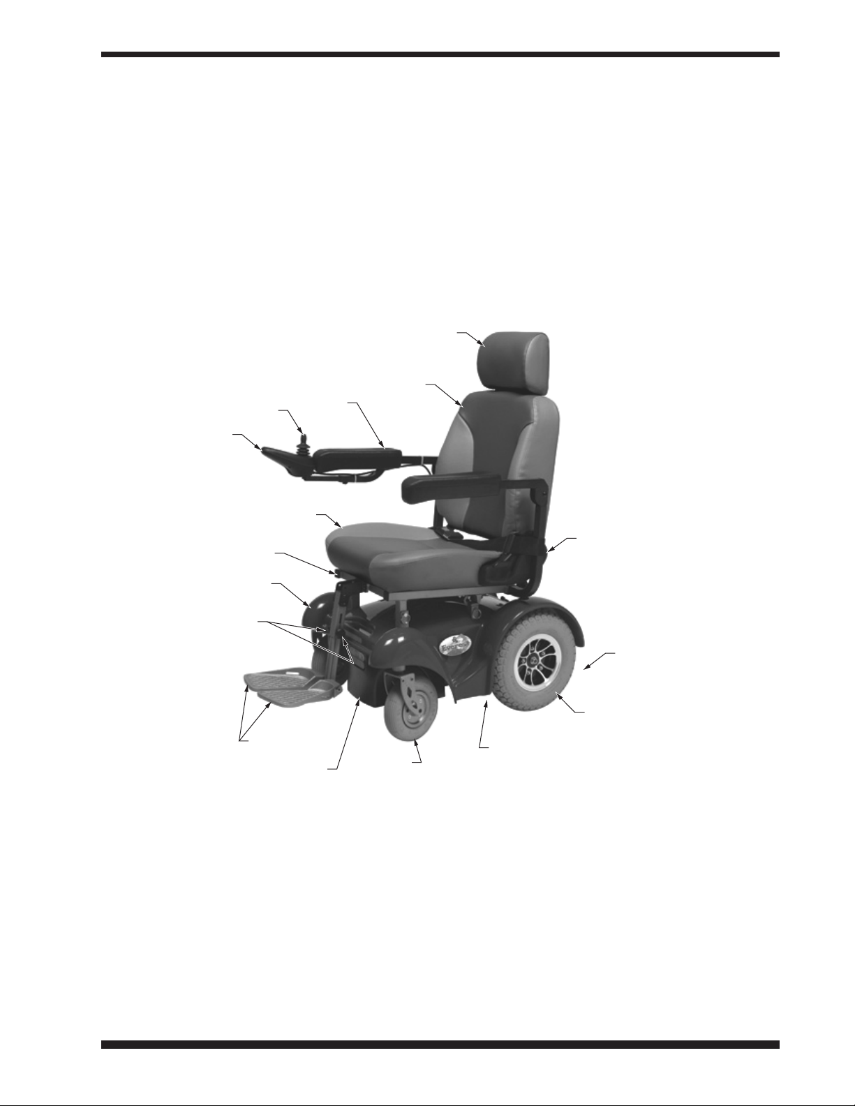
Cowl
End Cover with Circuit Breaker
(at Rear of Front Wheel Drive)
Adjustment Knob,
Footplate Extension
Length
Seat
Seat Frame
Hand
Control
Joystick
Adjustment Knob for
Width Between Arms
Drive Wheel
Arm
Back
Headrest
Footplate
Caster
Behind Drive Wheels:
Anti-Tippers (at Front
of Front Wheel Drive)
Beneath Cowl:
Base Frame, Batteries,
Motors, Controller
e Everest with Captain Seat is designed to provide the highest degree of independence and mobility.
It offers superior maneuverability and exceptionally tight turning capability. e theoretical range of the
Everest with Captain Seat is approximately 10 miles (16 km) with a 220 pound (100 kg) user
on a hard level surface with fully charged U1 sealed batteries, tested per ANSI/RESNA Specification
WC04 Energy Consumption. Actual range will vary according to your weight, the amount of start/stop
driving, ambient temperature, and the terrain on which you travel with your wheelchair. As you become
acquainted with your wheelchair, its range and performance capabilities will become apparent. e Everest with Captain Seat, Rear Wheel Drive model, is illustrated below. Main features are identified.
e Everest with Captain Seat power drive system consists of two independent drive wheels, a hand
control, the controller, independent, direct drive right and left motors, and two twelve volt batteries that
provide power.
e motors operate in both the forward and reverse direction. Motor speed and direction are controlled
by the joystick. e joystick commands are interpreted and applied to the motors by the controller.
POWER DRIVE SYSTEM
11Everest with Captain Seat Owner's Manual GF0600050RevE06, August 2006
Page 12
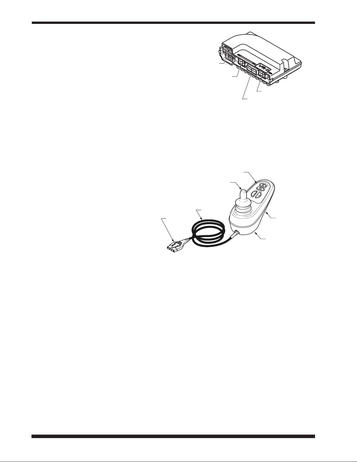
CONTROLLER
VR2 controller *
* VR2 is a trademark of
PG Drives Technology, Inc.
joystick
connector
motor 1
connector
motor 2 connector
power connector
(to batteries)
VR2 hand control
cable
controller
connector
joystick
control panel
battery charger
and programmer
receptacle
mounting holes
See picture at right. e controller is mounted below the seat. e controller contains the connectors to the rest of the wheelchair control system.
e connectors used by Everest are labelled in
the picture above - connectors not labelled in this
picture are not used by this wheelchair's control
system.
HAND CONTROL
See picture at right. e hand control is
mounted at the front of either arm. e
hand control contains the joystick, battery
charger receptacle (also used for the optional
programmer), mounting holes for the extension bracket, and those features found on the
control panel, shown on the next page: the
ON/OFF button, battery indicator, maximum speed/profile indicator, horn button,
speed profile decrease button, and speed/profile increase button. eir descriptions follow.
Joystick
e joystick controls the speed and direction of wheelchair travel. e further you move the joystick
from the rest position, the faster your wheelchair will move. When the joystick is returned to the neutral
(center) position or released, the control system will bring the wheelchair to a smooth stop. Upon stopping, electromechanical park brakes will engage to prevent the wheelchair from rolling.
Moving the joystick forward (away from the user) causes the wheelchair to move forward. Moving the
joystick back (toward the user) causes the wheelchair to travel in reverse. When the joystick is moved
right to 3 o'clock position, the wheelchair will turn to the right; when the joystick is moved left to
9 o'clock position, the wheelchair will turn to the left.
Battery charger receptacle (and optional programmer receptacle)
e receptacle for the battery charger (and optional programmer) is located on the underside of the controller, as shown above. Use only the battery charger supplied with the wheelchair.
Controller cable
e controller cable plugs into the controller.
12 GF0600050RevE06, August 2006 Everest with Captain Seat Owner's Manual
Page 13

VR2 hand control
control panel
battery indicator
horn button
speed/profile
increase button
ON/OFF button
maximum speed/
profile indicator
speed/profile
decrease button
Hand control panel features (see picture below right)
ON/OFF button
e ON/OFF button switches wheelchair power
on and off. When wheelchair power is on, the battery indicator illuminates.
Battery indicator
e three-color (green, yellow and red) battery
indicator illuminates when wheelchair power is
on. e battery indicator shows the charge level of
the batteries. As the batteries discharge, the lights
go off from green to red, similarly to an automobile's gas gauge (all lights on = full). When the batteries are nearly discharged, only the red lights will
illuminate. When one red light flashes slowly, charge batteries immediately. When you switch wheelchair
power on, the battery indicator shows an estimate of the remaining battery charge (the reading will be
more accurate about a minute after you start driving the wheelchair). e battery indicator also provides
a diagnostics display when wheelchair control system problems occur. See TROUBLESHOOTING for
a description of the battery indicator diagnostics.
Maximum speed / prole indicator
is 5-segment display indicates the maximum speed setting or which drive profile is selected, if drive
profiles have been programmed.
Horn button
is button operates the wheelchair's horn.
Speed / prole decrease button
is button decreases the maximum speed setting or selects a lower drive profile, if drive profiles have
been programmed.
Speed prole increase button
is button increases the maximum speed setting or selects a higher drive profile, if drive profiles have
been programmed.
BATTERIES
Please see Section VII, BATTERIES, which also describes the battery charger included with your Ever-
est with Captain Seat. Charge the batteries fully before operating your wheelchair. For installation and
charging information, refer to Section VII, BATTERIES.
CIRCUIT BREAKER
Your Everest with Captain Seat is equipped with a circuit breaker to protect the electrical circuits from
overload. It is located in the base end cover (back of wheelchair for front wheel drive; front of wheelchair
for rear wheel drive). In the event of an overload, the circuit breaker button will pop out. To reset the
circuit breaker, push the button in.
13Everest with Captain Seat Owner's Manual GF0600050RevE06, August 2006
Page 14

V OPERATING INSTRUCTIONS
Read and understand all safety precautions before operating your wheelchair.
1. Charge the batteries fully before use. For battery installation and charging information, refer to Section VII, BATTERIES.
2. Engage the drive wheels by turning the drive engagement levers to the outside. See the labels that
specify ON and OFF on the cowl next to the drive engagement levers; ON for engaged, and OFF
for disengaged. e drive engagement levers are located:
Front wheel drive: Toward the front of the wheelchair. Drive engagement levers are pointing
toward the rear of the wheelchair when engaged and inward when disengaged.
Rear wheel drive: Toward the rear of the wheelchair. Drive engagement levers are pointing to-
ward the front of the wheelchair when engaged and inward when disengaged.
3. With the joystick in neutral, turn the hand control ON/OFF button ON.
4. Adjust to a low speed or drive profile (if drive profiles have been programmed).
5. Move the joystick gently in the direction in which you wish to travel. If you desire a higher speed,
adjust the speed/profile increase button.
6. To stop the wheelchair, release the joystick to the neutral (center) position. e control system will
bring the wheelchair to a smooth stop. Upon stopping, electromechanical park brakes will engage to
prevent the wheelchair from rolling.
7. Attempting to overcome a stall condition may trip the circuit breaker located in the base end cover.
In the event of an overload, the circuit breaker button will pop out. To reset the circuit breaker, push
the button in.
Front wheel drive: e base end cover / circuit breaker is located at the rear of the wheelchair.
Rear wheel drive: e base end cover / circuit breaker is located at the front of the wheelchair.
14 GF0600050RevE06, August 2006 Everest with Captain Seat Owner's Manual
Page 15
VI ADJUSTMENTS
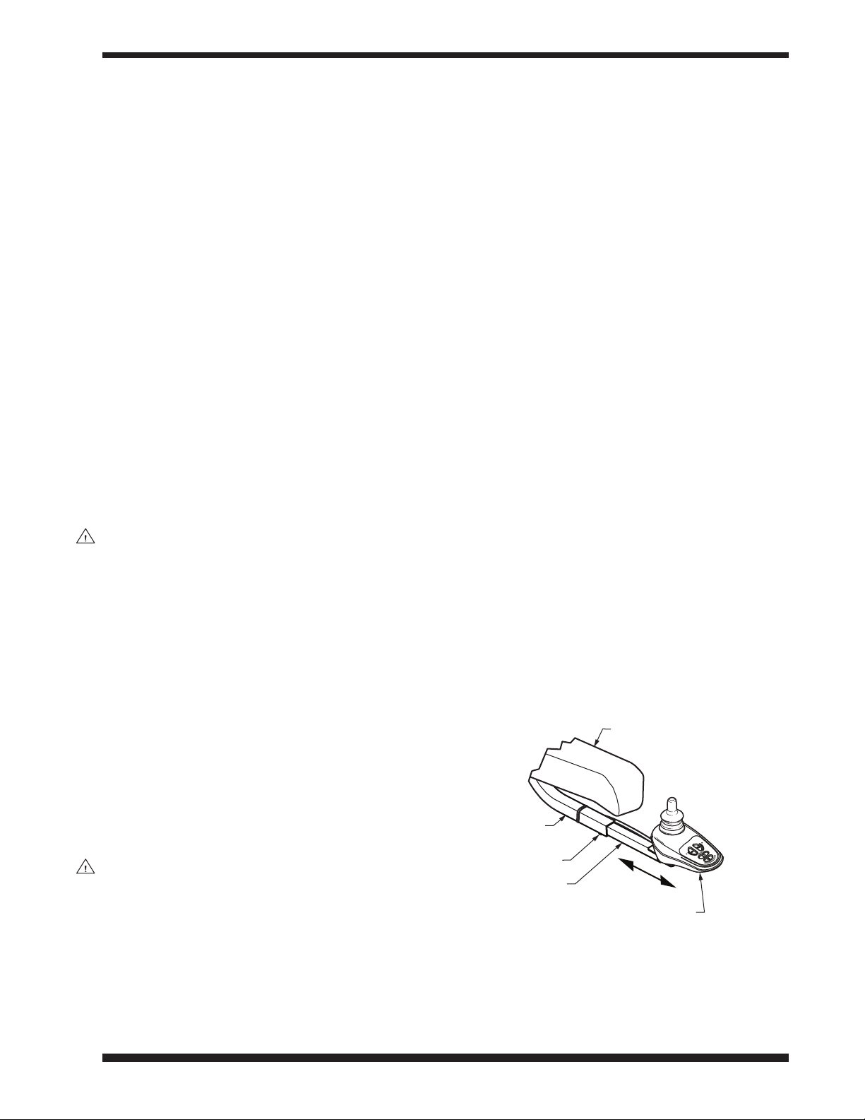
arm
set screw
extension
arm
extension tube
hand control
adjust hand control extension
backward / forward
e Everest with Captain Seat offers several adjustments to make it easier and more comfortable to drive.
Adjustments are divided by component: Arm, Back, Headrest, Seat, Cowl, Front Rigging.
Section VIII, MAINTENANCE, offers preventive maintenance suggestions for keeping your wheelchair
in excellent condition; ensure that all components are in excellent condition before adjusting. e following are recommended methods; after a few adjustments, you may develop your own. Always consult
your qualified Graham-Field Health Products dealer for assistance.
e person performing adjustments on the Everest with Captain Seat has the responsibility of making
certain that the user can safely operate the wheelchair with the adjustments selected. is person must
evaluate the user's ability, weight, physical condition, the environment in which the wheelchair will be
used, and the terrain over which the wheelchair will travel.
Specific tools needed to perform each adjustment are identified in adjustment sections. A complete list of
tools needed to perform all adjustments in Section VI follows:
Cable ties
M13 wrench
M10 wrench
M8 wrench
M5 hex key
M4 hex key
WARNING: Ensure that the wheelchair power switch is in the OFF position before per-
forming adjustments.
ARM—CONTROLS
Adjust hand control extension backward & forward
Tools needed: M4 hex key
e hand control can be moved forward and backward along arm:
1. Use M4 hex key to loosen—not remove—set
screw shown in picture at right.
2. Slide extension within arm extension tube to
preferred position.
3. Use M4 hex key to tighten set screw.
WARNING: Ensure that hand control
extension is locked in place
before occupying or operating wheelchair.
15Everest with Captain Seat Owner's Manual GF0600050RevE06, August 2006
Page 16

Adjust hand control extension—change sides
right
upper arm
cable tie
right
lower arm
hand control
connector
hand control cable
hand control
extension
arm
extension tube
mounting hardware
hand
control
seat frame
adjust hand control extension—
change sides
(seat and back not shown)
Tools needed: M13 wrench, M5 hex key, cable ties
e hand control can be mounted on either the left or right side. Only the side with the hand control
has an arm extension tube, as shown in picture at right. To change sides, you will remove both upper
arms and switch them (in picture at right, hand control is shown mounted on the right arm):
1. Engage the drive wheels (with the drive engagement levers) and turn wheelchair power
off.
2. Find the end of the hand control cable and
disconnect the hand control connector
from the extension cable connector where it
emerges from a hole in the cowl.
3. Use M13 wrench and M5 hex key to
remove hardware that secures upper arm to
lower arm.
4. Slide upper arm free of lower arm. Take
care that hand control does not fall.
5. Repeat stems 3 and 4 for other arm.
6. Install arms in opposite positions.
7. Install mounting hardware that secures
upper arm to lower arm. Use M13 wrench
and M5 hex key to tighten hardware. Repeat for other arm.
8. Connect the hand control connector to the
extension cable where it emerges from a
hole in the cowl.
9. Ensure that the hand control cable won't
catch on anything in its new position. As
shown in picture, cable ties secure the cable
to the arm extension tube and the upper
arm, to prevent its catching on anything.
If cable is loose and could possibly catch
on anything, use a cable tie to secure it to a
part of the frame where it will not contact
any moving parts.
WARNING: Ensure that arms are securely mounted, extension is securely mounted,
cables are secured, and that cables are away from all moving parts before
occupying or operating wheelchair.
16 GF0600050RevE06, August 2006 Everest with Captain Seat Owner's Manual
Page 17

Adjust arm space from seat frame (width between arms)
right arm
lower tube
left arm
lower tube
adjustment knob
seat frame tube
adjust arm space from seat frame
(width between arms)
screw
upper arm
lower arm tube
adjust arm height
Arm space from wheelchair is adjustable by changing the position of the lower arm tube in the seat tube.
Both arms are independently adjustable.
1. Turn adjustment knob to
free lower arm tube to move
inside seat tube (see picture at
right).
2. Slide lower arm tube to de-
sired position inside seat tube.
3. Turn knob to secure lower
arm tube inside seat tube.
Ensure that knob is tightened
enough to hold lower arm
tube firmly in place.
4. Perform steps 1-3 for other
arm.
5. Ensure that both arms are
mounted at the same distance
from seat frame.
WARNING: Ensure that lower arm tubes are locked in place before occupying or operat-
ing wheelchair.
Adjust arm height
Tools needed: M5 hex key
Arm height is adjustable by removing the screw that secures the upper arm inside the lower arm tube and
moving the upper arm to a new position. ere are three positions approximately 5/8 inch apart.
1. Use M5 hex to remove the screw that secures the upper arm in
the lower arm tube (see picture at right).
2. Slide upper arm to desired position inside lower arm tube.
3. Reinstall screw. Use M5 hex key to tighten.
4. Perform steps 1-3 for other arm.
5. Ensure that both upper arms are mounted at the same height.
WARNING: Ensure that arms are secure before occupy-
ing or operating wheelchair.
17Everest with Captain Seat Owner's Manual GF0600050RevE06, August 2006
Page 18

BACK
adjust back angle
back
latch
Fold back down
1. Engage the drive wheels (with the drive engagement levers) and turn wheelchair power off.
2. Pull up on latch at left side of seat. Hold back
by top and push it down, toward front of
wheelchair.
3. To restore the back to upright position, pull it
back up until latch locks into place. Ensure that
latch is locked in place.
WARNING: Ensure that back is locked in
upright position before occupying or operating wheelchair.
Adjust back angle
e back angle is adjustable to five positions.
1. Engage the drive wheels (with the drive engagement levers) and turn wheelchair power off.
2. Pull up on latch at left side of seat. Move back
to desired angle.
3. Let go of back when latch locks into place.
Ensure that latch is locked in place.
WARNING: Ensure that back is locked in upright position before occupying or operating
wheelchair.
18 GF0600050RevE06, August 2006 Everest with Captain Seat Owner's Manual
Page 19

headrest
back
button
latch
adjust headrest height
HEADREST
e headrest is adjustable to four positions, by depressing the button latch on the left headrest post (see
picture at right).
Adjust headrest height
1. Depress the button latch with one hand. With
the other hand, move the headrest up or down to
desired position.
2. Release when button latch has locked into place.
Ensure that button latch is locked in place.
WARNING: Ensure that headrest is locked
in place before occupying or
operating wheelchair.
19Everest with Captain Seat Owner's Manual GF0600050RevE06, August 2006
Page 20

SEAT
seat installed
locking pin
seat
seat frame
seat removed
seat frame
front mount tube
base frame
front mount tube
base frame
rear mount
tube
rear seat
frame hook
rear base
frame hook
You must remove the Everest with Captain Seat seat in order to perform certain seat height adjustments.
Note: Removing the seat is best performed with a partner so that you are able to use both hands to re-
move the seat.
Remove seat (refer to the pictures at right)
1. Engage the drive wheels (with the drive engagement levers) and turn wheelchair power off.
2. Find the end of the hand control cable and disconnect the hand control connector from the exten
sion cable connector where it emerges from a hole in the cowl.
3. Two locking pins secure the seat
frame to the base frame at the front
of the wheelchair. Remove these two
locking pins.
4. Lift the seat up and off the base,
moving the seat slightly forward to
disengage the seat frame from the
hooks at the back of the base that
secure seat frame to base frame.
Install seat (refer to the pictures
at right)
1. Slide the seat down and onto the
base frame. Engage the rear seat
frame hooks with the rear base
frame hooks; engage the front seat
frame mount tubes with the base
frame front mount tubes. Ensure
that rear seat frame hooks are engaged with rear base frame hooks
before continuing.
-
2. Install the two locking pins that
secure the seat frame to the base
frame at the front of the wheelchair.
3. Connect the hand control connector to the extension cable connector
where it emerges from a hole in the
cowl.
WARNING: Ensure that rear seat frame hooks are engaged with rear base frame hooks
20 GF0600050RevE06, August 2006 Everest with Captain Seat Owner's Manual
and that all four locking pins are locked in place before occupying or operating wheelchair.
Page 21

Adjust seat height (refer to the pictures on previous page)
Seat height has approximately one inch of adjustment. A small degree of extra tilt can also be gained by
placing the front of the seat in a higher position than the back of the seat.
1. Remove seat: Follow steps 1-4 in Remove seat on preceding page.
2. Remove the two locking pins that secure the rear seat mounts to the base frame at the rear of the
wheelchair.
3. Remove the two rear seat mounts and reinstall them in the desired position. Ensure that both rear
seat mounts are installed in identical positions.
4. Install the two locking pins that secure the rear seat mounts to the base frame.
5. Install seat: Follow steps 1-3 in the earlier section, Install seat
WARNING: Do not adjust seat height so that back is higher than front; this is an unsafe
position.
.
21Everest with Captain Seat Owner's Manual GF0600050RevE06, August 2006
Page 22

COWL
cowl installed
(front wheel drive shown)
rear seat
mount
locking pin
drive
engagement
lever
Remove cowl (refer to the picture at right)
1. Remove seat: Follow steps 1-4 in the earlier section, Remove seat.
2. Remove the two locking
pins that secure the rear seat
mounts to the base frame at
the rear of the wheelchair.
3. Remove the two rear seat
mounts.
4. Ensure that drive engage
ment levers are engaged, so
that levers will fit through
slots in cowl when cowl is
lifted over them.
Front wheel drive: Drive
engagement levers are
pointing toward the rear of
the wheelchair when engaged.
Rear wheel drive: Drive en-
gagement levers are pointing toward the front of the
wheelchair when engaged.
5. Lift cowl up and off base frame. ere are Velcro® strips at front and rear that secure cowl to base
frame; you must pull these loose to remove the cowl. *
* Velcro is a registered trademark of Velcro Industries B.V.
Install cowl (refer to the picture above)
1. Slide the cowl down onto the base frame. Press on the areas at front and rear where the Velcro strips
fasten the cowl to the base frame. Ensure that the cowl is securely fastened to the base frame at these
points.
2. Install the two rear seat mounts. Ensure that both rear seat mounts are installed at the same height.
3. Install the two locking pins that secure the rear seat mounts to the base frame.
22 GF0600050RevE06, August 2006 Everest with Captain Seat Owner's Manual
Page 23

FRONT RIGGING—CENTER-MOUNT FOOTREST
seat frame
footplate
extra angle mounting position
seat frame bracket
center tube
mounting
nut
adjustment knob
adjustment holes
WARNING: Ensure that the lowest point on the footplates clears the ground safely dur-
ing ascent or descent.
Flip footplates up
(see picture at right)
Hold the footplates by the front
and fold them up against the center
tube.
Adjust footplate extension
length (see picture at right)
Footplate extension length is adjustable in two ways. You can either
adjust footplate extension length
individually by loosening the knob
and moving it to a different adjustment hole, or adjust the position of
the footplate extension assembly on
the seat frame bracket.
Adjust individual footplate
extension length
1. Unscrew and remove adjust
2. Move footplate up or down in
3. Install and tighten knob.
4. Repeat for other footplate. Ensure that knobs are secure before occupying or operating wheelchair.
Adjust position of footplate extension assembly on seat frame bracket
1. Use M10 wrench and M4 hex key to remove mounting nuts and bolts, and remove footplate exten-
2. Reposition center tube in desired position on seat frame bracket.
3. Reinstall mounting nuts and bolts. Use M10 wrench and M4 hex key to tighten.
-
ment knob.
center tube to adjust footplate to desired position.
Tools needed: M10 wrench, M4 hex key
sion from seat frame bracket.
WARNING: Ensure that all parts of footrests are secure, and that footplate extension
assembly is securely mounted on seat frame, before occupying or operating
wheelchair.
23Everest with Captain Seat Owner's Manual GF0600050RevE06, August 2006
Page 24

VII BATTERIES
Batteries are of critical importance, require attention and maintenance, and will require periodic replacement. As batteries age, their ability to hold a charge decreases. Old batteries discharge much more
quickly than new batteries under the same driving conditions. is results in a decrease in the distance
the wheelchair can travel before batteries need to be charged. is decrease is often misinterpreted as a
problem with the wheelchair system, when in fact the batteries have simply reached the end of their useful lives and should be replaced. Properly maintained batteries can be expected to last approximately 9 to
18 months. e purpose of proper maintenance is to extend that life as much as possible, and to minimize the incidence of unsatisfactory wheelchair performance.
e Everest with Captain Seat uses two 12 volt deep cycle batteries, group size U1 or 22. For best performance, batteries with the highest possible amp-hour rating should be used.
s
Caution: Only deep cycle, sealed case construction batteries should be used in this device.
WARNING: Batteries contain sulfuric acid, which can burn eyes, skin, clothes, etc. Use
caution! Always wear safety glasses when working with batteries. If contact
occurs, flush immediately with water and get medical attention.
GUIDELINES TO EXTENDING BATTERY LIFE
• Give the batteries a full charge before using them for the first time.
• Limit use of new batteries for the first ten charge/discharge cycles—avoid deeply discharging the batteries. New batteries are not capable of their rated output until they have been discharged a number
of times.
• Recharge batteries after every discharge. Discharging batteries deeply before recharging them will
shorten battery life. Do not leave partially discharged batteries idle for several days; charge them as
soon as possible after discharging.
• Charge batteries fully each time before using. Allow the charger to finish its charge cycle once
started. is will help prevent deeply discharging the batteries. Unlike some rechargeable batteries,
the batteries used on wheelchairs do not exhibit a significant “memory effect”—they will recharge to
their full capacity, even if only partially discharged before each charge.
• If you must store your wheelchair for a long period of time, charge the batteries weekly.
• Perform regular maintenance on the batteries. See maintenance schedule in Section VIII,
MAINTENANCE, for recommended regularity.
24 GF0600050RevE06, August 2006 Everest with Captain Seat Owner's Manual
Page 25

BATTERY CHARGER
back
panel
front
panel
AC connector
output
connector
AC voltage
switch
battery
capacity level
indicator
status
indicator
ON/OFF
switch
output fuse
e Everest with Captain Seat 5-amp battery charger, included with the wheelchair, is pictured and
described below. is battery charger is capable of charging both gel and sealed lead acid batteries. Please
read this entire section, including SAFETY—CHARGING THE BATTERIES, before charging your
batteries.
Battery charger front panel
Output cable and connector
e output connector plugs into the battery charger receptacle on the underside of the hand control to
charge the batteries.
Status indicator
Green LED illuminates when battery charger power is switched on, then flashes a different pattern for
each charging mode (fast charge, deep charge, float charge, or maintain).
Battery capacity level indicator
One red or yellow LED illuminates at a time to show state of battery charge: ≤30% (red),
50% (red), 70% (yellow), 85% (yellow), or 100% (yellow).
Output fuse
See Check/replace the output fuse in TROUBLESHOOTING for directions on changing the output
fuse.
Battery charger back panel
ON/OFF switch
e ON/OFF switch turns battery charger power on and off.
AC voltage switch
e AC voltage switch changes the voltage between 115 volts and 230 volts. Set to 115 volts for use in
the U.S. and Canada. See Battery voltage switch on wrong setting in TROUBLESHOOTING for
directions on switching voltage.
AC connector
e AC connector plugs into the power outlet to charge the batteries.
25Everest with Captain Seat Owner's Manual GF0600050RevE06, August 2006
Page 26

SAFETY—CHARGING THE BATTERIES
WARNING: Do not use a household extension cord if the charger plug does not reach
the 115 volt outlet. Use of an improper extension cord could result in fire
and electric shock. If an extension cord must be used, use a three conductor No. 16 AWG (or heavier) cord with ground, properly wired, in good electrical condition, and keep it as short as possible.
WARNING: Do not use cords that are damaged or defective. Use of a damaged or de-
fective cord could result in fire or electric shock.
WARNING: Locate all battery charger cords so that they will not be stepped on, tripped
over, or otherwise subjected to damage or stress.
WARNING: To prevent electrical shock, do not touch uninsulated parts of the battery
charger output connector, battery connectors, or battery terminals. Ensure
that all electrical connectors are in good working condition. Do not use connectors that are cracked, corroded, or do not make adequate electrical contact. Use of a damaged or defective connector could result in fire or electric
shock.
WARNING: Ensure that the area around battery charger and batteries is well ventilated
while batteries are being charged. Do not allow clothing, blankets, or other
material to cover battery charger. Do not place battery charger under a bed.
WARNING: Keep sparks, flame, and smoking materials away from batteries. No smok-
ing!
WARNING: Battery chargers can ignite flammable materials and vapors. Do not use
near fuels, grain dust, solvents, thinners, or other flammables.
WARNING: Batteries generate gases which can be explosive. To prevent arcing or burn-
ing near batteries, do not disconnect battery charger output connector from
wheelchair battery charger receptacle when battery charger is operating.
If the charge cycle must be interrupted, move the battery charger ON/OFF
switch to OFF and disconnect the battery charger AC connector from the
power outlet, then disconnect the battery charger output connector from
the wheelchair battery charger receptacle.
WARNING: To avoid damage to any of the battery charger connectors and their cords,
disconnect by grasping the plug body and pulling it straight out of the outlet
or receptacle. DO NOT pull on the cord. DO NOT twist, rock or pull the connector sideways.
26 GF0600050RevE06, August 2006 Everest with Captain Seat Owner's Manual
Page 27

WARNING: Do not use battery chargers not supplied by Graham-Field Health Products.
status
indicator
battery capacity
level indicator
Battery chargers not supplied by Graham-Field Health Products could damage the controller and the battery charger. Electrical arcing could result,
which could cause severe personal injury, explosion, and fire.
Charging the batteries
Note: Before charging the batteries, read the rest of this manual, especially the Battery Charger section.
Note: As a safety feature, the wheelchair is inoperable during charging.
1. Ensure that power to both wheelchair and battery charger is OFF.
2. Connect battery charger output connector to receptacle on bottom of hand control.
3. North America: Plug the battery charger AC connector into a properly grounded, 115 volt, 60 cycle
single phase power outlet.
Note: Ensure that the battery charger AC voltage switch is set on the appropriate voltage for your loca-
tion.
4. Place battery charger power switch in the ON position. e green status indicator LED will illu-
minate when battery charger power is switched on, then flash a different pattern for each charging
mode automatically selected by the battery charger:
Always off: No AC power
Always on (nonflashing): Batteries not connected
Flash 1/2 second on, 1/2 second off: Fast charge (normal
charge)
Flash 2 seconds on, 2 seconds off: Float charge (almost fin-
ished)
Flash 4 times, 1 second on, 1 second off: Maintain charge
(charge complete)
Flash 2 times, 1 second off: Deep charge (batteries severely
discharged)
e battery capacity level indicator LEDs will illuminate one
at a time to show the state of battery charge: ≤30% (red),
50% (red), 70% (yellow), 85% (yellow), or 100% (yellow).
When the batteries are fully charged, the battery capacity level
indicator's 100% LED will illuminate and the status indicator will show maintain mode.
5. Allow adequate time to bring the batteries up to a full charge—the actual time required to recharge
the batteries will depend on discharge condition. e charger supplied with the wheelchair is automatic, and will not damage the batteries if left connected after batteries are fully charged.
6. When batteries are fully charged, place battery charger power switch in the OFF position.
7. Remove battery charger output connector from hand control receptacle.
Note: If you experience a problem with your battery charger, please see Troubleshooting, battery charger
in the TROUBLESHOOTING section
27Everest with Captain Seat Owner's Manual GF0600050RevE06, August 2006
Page 28

REMOVE AND INSTALL BATTERIES
WARNING: Batteries can supply a large amount of current. Do not wear jewelry or
watches when working on batteries. Take care not to connect the terminals
accidentally with anything metal; severe burns could result.
REMOVE BATTERIES
Tools needed: Group 22 batteries: two 1/2" wrenches; U1 batteries: two 7/16" wrenches
WARNING: Ensure that wheelchair power is off before removing batteries.
To access the batteries, you will first remove the seat and cowl.
1. Please see Section VI, ADJUSTMENTS, SEAT, Remove Seat, and perform steps 1-4.
2. Please see Section VI, ADJUSTMENTS, COWL, Remove Cowl, and perform steps 1-5.
3. e base frame and batteries will then be exposed.
4. Unfasten battery straps.
5. Disconnect black connectors at each battery that connect battery cables to power cable.
6. Lift batteries up and out of base frame.
7. Remove battery cables from both batteries:
Group 22 batteries: Use two 1/2" wrenches to remove nuts and screws that secure wire terminals to
battery terminals. Set aside for reassembly.
U1 batteries: Use two 7/16" wrenches to remove nuts and screws that secure wire terminals to battery
terminals. Set aside for reassembly.
28 GF0600050RevE06, August 2006 Everest with Captain Seat Owner's Manual
Page 29

INSTALL BATTERIES
slot
bracket
front battery
front
rear
rear battery
controller
location
install batteries
(rear wheel drive shown)
connect batteries
black
connector
battery
terminal
battery
terminal
power
cable
black
connector
battery
cable
battery
cable
Note: If you are changing battery size, you will need to reposition the brackets that keep the batteries
secure in the base frame. e brackets should be snug enough to keep the batteries from moving.
Adjust battery brackets (if necessary)
Tools needed: M4 hex key
1. Use M4 hex key to loosen screws enough
so that bracket is free to move along slots.
Reposition bracket in desired location.
2. Use M4 hex key to tighten screws so that
bracket does not move.
3. Repeat for other bracket.
Install batteries
Tools needed:
Group 22 batteries: two 1/2" wrenches; U1 batteries: two 7/16" wrenches
Note: Observe controller location: front wheel drive controller is located at left rear; rear wheel drive
1. Place batteries lengthwise in base frame, as
shown at right.
Group 22 batteries: Install battery cable
U1 batteries: Install battery cable positive
controller is located at right front. Position the battery adjacent to the controller with its battery
terminals away from the controller, to reduce the possibility of arcing. Position the other battery
with its terminals on the opposite side from the first battery as shown below, to allow maximum
space for routing cables.
positive wire terminal (+) on positive
battery terminal (+) of first battery as
shown above. Use two 1/2" wrenches to
secure. Install battery cable negative wire
terminal (-) to negative battery terminal
(-) of first battery as shown. Use two 1/2"
wrenches to secure.
wire terminal (+) on positive battery terminal (+) of first battery as shown above.
Use two 7/16" wrenches to secure. Install
battery cable negative wire terminal (-) to
negative battery terminal (-) of first battery as shown. Use two 7/16" wrenches to
secure.
29Everest with Captain Seat Owner's Manual GF0600050RevE06, August 2006
Page 30

2. Install second battery cable as described in step 1.
3. Ensure that all wires are connected as specified. Ensure that all connections are secure.
4. To retard corrosion, coat battery posts and terminals with petroleum jelly after all connections are
made.
5. Connect black connectors that connect battery cables to power cable.
6. Fasten battery straps.
7. Replace the cowl. Please see ADJUSTMENTS, COWL, Install cowl, and perform steps 1-3.
8. Replace the seat. Please see ADJUSTMENTS, SEAT, Install seat,
and perform steps 1-3.
9. Ensure that the circuit breaker located in the end cover is properly set by depressing its button (back
of wheelchair on front wheel drive, front of wheelchair on rear wheel drive).
10. Do not attempt to operate the wheelchair unless batteries are installed as instructed above.
11. Do not attempt to operate wheelchair until batteries are fully charged.
WARNING: Ensure that batteries are installed as described before operating wheel-
chair.
WARNING: Ensure that cowl is securely fastened to base frame, rear seat frame hooks
are engaged with rear base frame hooks, and that all four locking pins are
locked in place before occupying or operating wheelchair.
WARNING: Ensure that all cables are away from the moving parts of the wheelchair.
30 GF0600050RevE06, August 2006 Everest with Captain Seat Owner's Manual
Page 31

REGULAR BATTERY MAINTENANCE
WARNING: Batteries can supply a large amount of current. Do not wear jewelry or
watches when working on batteries. Take care not to connect the terminals
accidentally with anything metal; severe burns could result.
WARNING: Batteries contain sulfuric acid, which can burn eyes, skin, clothes, etc. Use
caution! Always wear safety glasses when working with batteries. If contact
occurs, flush immediately with water and get medical attention.
Clean batteries
Needed: baking soda
1. You will first need to remove the batteries; see Remove batteries in previous REMOVE AND IN
STALL BATTERIES section—follow steps 1-7.
2. Clean outside of batteries, and inside and outside of battery box, with a solution of one tablespoon
baking soda to ten ounces water.
3. Rinse with clear water. Allow to dry.
4. Ensure that batteries and connectors are clean and dry. Reinstall batteries; see Install batteries
in
previous REMOVE AND INSTALL BATTERIES section—follow steps 1-11.
Clean battery terminals
Tools needed: wire brush or battery terminal cleaning tool
1. You will first need to remove the batteries; see Remove batteries in previous REMOVE AND
INSTALL BATTERIES section—follow steps 1-7.
2. Clean all battery terminals and clamps with a wire brush or battery terminal cleaning tool (this can
be purchased at most auto parts stores).
3. Reinstall batteries; see Install batteries in previous REMOVE AND INSTALL BATTERIES sec-
tion—follow steps 1-11.
31Everest with Captain Seat Owner's Manual GF0600050RevE06, August 2006
Page 32

VIII MAINTENANCE
MAINTENANCE SCHEDULE
Procedure Perform at least every
Day Week 2 weeks month 3 months 6 months
Charge batteries 4
Check joystick 4
Check cables & connections 4
Check tire wear 4
Check controller & park brakes 4
Check anti-tippers 4
Wipe off base and seat frame 4
Check arms 4
Check footrests 4
Check & clean upholstery 4
Clean base and seat frame 4
Clean batteries 4
Check caster forks 4
Clean battery terminals 4
Inspect motor brushes 4
Check bearings 4
Check battery state-of-charge as needed
Protect your Everest & Jennings® Everest with Captain Seat by having it serviced regularly. Proper care
and maintenance are essential to keep your wheelchair in safe working condition. Periodic inspection,
adjustment, and replacement of worn parts will provide many years of superb performance. When you
believe that a component or part of your Everest with Captain Seat is not functioning properly, immediately contact your Graham-Field Health Products dealer, as a potentially hazardous condition could
result. Only excellent condition is acceptable where safety is concerned.
Service manual
ere is no service manual for the Everest with Captain Seat. Please contact your Graham-Field Health
Products dealer with service questions not answered by this manual.
Note: Graham-Field Health Products recommends that you have a qualified dealer perform a six month
maintenance check, as the dealer may find and correct a problem which might otherwise go undetected and eventually cause more serious problems and/or personal injury.
Do-it-yourself maintenance
You can do many of the scheduled maintenance tasks yourself, if you have mechanical ability and a few
basic tools. Refer to the maintenance schedule below for the recommended regularity of each procedure.
If any maintenance procedure is not clear to you, ask your Graham-Field Health Products dealer for assistance.
s
Caution: Improper maintenance can cause operating problems and may affect your warranty.
WARNING: Unauthorized modification or the use of non-Everest & Jennings® replace-
ment parts could change the structure of the wheelchair, void the warranty,
and create a hazardous condition resulting in serious personal injury.
32 GF0600050RevE06, August 2006 Everest with Captain Seat Owner's Manual
Page 33

List of tools and supplies
e tools and cleaning supplies listed will assist in the procedures outlined in Section VIII.
Soft cloth
Mild soap and water solution
General care
Always evaluate the overall operation of your wheelchair. It should function with ease and should travel
straight without excessive drag or pull to one side.
Remember, your qualified Graham-Field Health Products dealer knows your wheelchair best when it
comes to service and repairs. Contact your dealer with any questions or concerns regarding the safe
operation and maintenance of your wheelchair. Regular maintenance is important for your safety and
continued operation of your wheelchair.
Charge batteries
Charge the batteries daily. See Section VII, BATTERIES, Charging the batteries.
Check joystick
Check the hand control joystick daily. Turn wheelchair power off. Check that the joystick is not bent
or damaged, and that it returns to center when you release it. If there is a problem, do not operate the
wheelchair. Contact your dealer.
Check the rubber boot around the base of the joystick for damage or splitting. A visual check is sufficient—do not handle the boot. If there is a problem, contact your dealer.
ere are no serviceable parts in the controller or hand control. If you have problems with these components, see Section IX, TROUBLESHOOTING; if you are unable to resolve them, contact your Gra-
ham-Field Health Products dealer.
Check cables and connections
Inspect all control system plug connectors visually at least once a week to be sure that they are securely
fastened. Cable connections for both front wheel drive and rear wheel drive wheelchairs are shown on
the following pages.
33Everest with Captain Seat Owner's Manual GF0600050RevE06, August 2006
Page 34

front of wheelchair
control system cable connections,
front wheel drive
circuit breaker
end cover
right
motor
power cable
right
motor
cable
left
motor
left
motor
cable
controller
battery charger /
programmer
connector
(underside)
hand control
battery
cable
battery
cable
front battery
rear battery
34 GF0600050RevE06, August 2006 Everest with Captain Seat Owner's Manual
Page 35

front of wheelchair
control system cable connections,
rear wheel drive
circuit breaker
end cover
left motor
power cable
left motor cable
right motor
right motor cable
controller
battery charger /
programmer
connector
(underside)
hand control
battery
cable
battery
cable
rear battery
front battery
35Everest with Captain Seat Owner's Manual GF0600050RevE06, August 2006
Page 36

Check tires
Examine tires at least once a week for surface wear and cracks and replace them as needed. Tires should
be replaced when they become loose on the rims or cracks appear.
Check controller & park brakes
Perform the following at least once a week. It should be carried out on a level floor in a quiet area with at
least one meter (40 inches) of clear space around the wheelchair.
Turn wheelchair power on. Check that after one second the power indicator lights remain on. Push the
joystick slowly forward until you hear the brakes release. e wheelchair may start to move. Immediately
release the joystick—you must be able to hear the park brakes operate within a few seconds. Repeat the
test three times, pushing the joystick in reverse, left and right, respectively. If there is a problem, do not
operate the wheelchair. Contact your dealer.
Repairs of the electromechanical park brakes, which keep your Everest with Captain Seat from rolling
when stopped, should only be performed by an Graham-Field Health Products dealer.
Check anti-tippers
Check the anti-tippers at least once a week. Ensure that all parts of the anti-tippers are securely fastened.
Clean frame
Needed: soft cloth, mild soap and water solution
Wipe off base and seat frame frequently, at least once a week, using a soft cloth. Dry the wheelchair immediately if exposed to moisture. Clean frame every three months with a mild soap and water solution.
e frame does not need to be waxed. Do not use solvents, abrasive waxes, caustic chemicals or spray
silicone. Never use abrasive cleansers; they could scratch the finish. Never use steam or high pressure
cleaners.
Check & clean upholstery
Needed: soft cloth, mild soap and water solution
Check back and seat upholstery material at least once a month. Inspect for rips, tears and worn spots.
Clean back and seat upholstery material at least once a month with a soft cloth and a mild soap and
water solution.
Check arms
Check arms at least once a month. Inspect for sharp edges or cracks which could weaken the armrest.
Ensure that all attaching hardware is present and tight.
Check footrests
Check footrests at least once a month. Inspect the mounting hardware to confirm secure fasteners.
Check for cracks, burrs or sharp edges. Ensure that the footplate extension knobs are secure and footplates will not accidentally slip.
36 GF0600050RevE06, August 2006 Everest with Captain Seat Owner's Manual
Page 37

Check caster forks
Check the caster stems/forks for proper rotation at least every three months. e caster fork must swivel
freely to facilitate steering and handling. Adjusting the stem nut varies the amount of force required
to turn the caster. If the nut is too loose, the caster will flutter or shimmy; if the nut is too tight, the
wheelchair will be difficult to steer. If the caster requires adjustment, or the caster stem bearing requires
replacement, visit a qualified Graham-Field Health Products dealer. Ensure that stems are firmly attached
to forks, and that forks and stems are not bent. Evaluate all threads, locking nuts and bearings.
Clean Batteries
Perform this at least every three months. See Section VII, BATTERIES, REGULAR BATTERY MAINTENANCE, Clean batteries,
for this procedure.
Clean battery terminals
Clean battery terminals at least every six months. See Section VII, BATTERIES, REGULAR BATTERY
MAINTENANCE, Clean battery terminals, for this procedure.
Inspect motor brushes
e motor brushes should be inspected for wear every six months and replaced as needed. is should be
performed by a Graham-Field Health Products dealer.
s
Caution: Badly worn brushes can result in damage to the motors or controller.
s
Caution: After replacing the brushes, run the wheelchair gently for the first few miles to allow
the brushes to seat properly.
Check bearings
e Everest with Captain Seat has bearings only in the caster wheels, not in the drive wheels. Always
be alert for unusual noises in the bearings or excessive caster wobble. ese signs indicate that the bearings are becoming worn and may require replacement. e caster bearings should be inspected every six
months and replaced as needed. is should be performed by a Graham-Field Health Products dealer.
37Everest with Captain Seat Owner's Manual GF0600050RevE06, August 2006
Page 38

IX TROUBLESHOOTING
label
base frame
label
cowl
label
seat frame
label
hand control
SERIAL NUMBER LOCATIONS
Several components of your power wheelchair have been assigned serial numbers at the factory. ere
may be times when you will need to provide a serial number; for example, if you order replacement
parts. e following diagrams are provided to help you find the serial number labels.
Base frame
e base frame serial number label is located at the
caster end of the base frame, as shown at right (front
of the base frame for rear wheel drive; back of the base
frame for front wheel drive).
Cowl
e cowl serial number label is located on the underside of the cowl, as shown at right.
Seat frame
e seat frame serial number label is located at the
back of the seat frame, as shown at right.
Hand control
e hand control serial number label is located on
the underside of the hand control, as shown at right.
You must remove the hand control from its mounting
bracket to see this serial number label. Please note that
the hand control has an additional serial number label
on the side, which is not intended to be permanent;
you may remove it.
38 GF0600050RevE06, August 2006 Everest with Captain Seat Owner's Manual
Page 39

GENERAL TROUBLESHOOTING
Continual use of your Everest with Captain Seat necessitates maintenance, especially if the factory-set
adjustments have been altered. If you are unsure of the solution or unable to diagnose the problem, do
not hesitate to ask your Graham-Field Health Products dealer for assistance. Most power drive problems
are battery related. As batteries age, their ability to hold a charge decreases. Older batteries discharge
much more quickly than new batteries under the same driving conditions. is results in a decrease in
the distance the wheelchair can travel before batteries need to be charged. is decrease is often misinterpreted as a problem with the wheelchair system, when in fact the batteries have simply reached the end
of their useful lives and should be replaced. Sometimes expensive components are unnecessarily replaced
when the batteries are the real problem. If an electrical problem exists, check the following:
BATTERIES
Make sure the batteries are fully charged. Test battery state-of-charge as described in Section VII, BATTERIES, REGULAR BATTERY MAINTENANCE. Keep the posts and terminals clean and tight.
CIRCUIT BREAKER
Your Everest with Captain Seat is equipped with a circuit breaker to protect the electrical circuits from
overload. It is located in the base end cover (front of wheelchair for rear wheel drive; back of wheelchair
for front wheel drive). In the event of an overload, the circuit breaker button will pop out. To reset the
circuit breaker, push the button in.
Note: If you experience a problem with your wheelchair and are unable to service it yourself, contact
the dealer from whom you purchased the wheelchair. If the dealer is unable to help you, contact
Graham-Field Health Products Customer Service Department .
Note: Use only Everest & Jennings® replacement parts. An Everest with Captain Seat parts catalog is
available through Graham-Field Health Products dealers (and on the internet, at www.grahamfield.com), to assist in the ordering of parts.
s
Caution:: A complete inspection of your wheelchair, including maintenance, servicing and safety
checks, should be handled by a qualified Graham-Field Health Products dealer at least once a year.
WARNING: Unauthorized modification or the use of non-Everest & Jennings® replace-
ment parts could change the structure of the wheelchair, void the warranty,
and create a hazardous condition, which could result in serious personal
injury..
39Everest with Captain Seat Owner's Manual GF0600050RevE06, August 2006
Page 40

TROUBLESHOOTING: CONTROLLER
A general diagnostic guide is first, followed by the battery indicator control system status display and the
battery indicator diagnostic guide. Use the general diagnostic guide first; if you are unable to solve your
problem, use the battery indicator diagnostic guide.
WARNING: If problems or fault indicators persist, do not attempt to operate the wheel-
chair. Operation of the wheelchair could be unsafe. Contact the dealer
from whom you purchased the wheelchair. If the dealer is unable to help
you, contact Everest & Jennings' Customer Service Department for a list of
qualified Graham-Field Health Products dealers in your area.
GENERAL DIAGNOSTIC GUIDE
SYMPTOM BATTERY POSSIBLE CAUSE CORRECTIVE ACTION
INDICATOR
LIGHTS
Wheelchair Off System off Turn ON/OFF button switch ON
won’t drive
Batteries not Connect batteries
connected
Batteries not Correct Connections
connected properly, or
polarity reversed
Circuit breaker open Reset circuit breaker
Batteries severely Recharge / replace batteries
discharged
Rapidash Controlsystemfault TheControllersafetycircuitshaveoperatedandtheControllerhas
(even with been prevented from moving the wheelchair. This indicates that there
joystick is a fault. Please follow this procedure:
released)
1. Switch off the control system.
2. Ensure that all Controller and wheelchair connectors are securely
mated.
3. Check battery condition.
4. Ifyoucan'tndtheproblem,tryusingthefollowingBattery
indicator diagnostic guide.
5. Turn the Controller on again and try to drive the wheelchair. If the
faultlightsashagain,
do not try to use the wheelchair; see your dealer.
Wheelchair On, steady All is well None
drives
Slowash Lowbatteries Controllerisfunctioningcorrectlybutyoushouldchargethebatteries
as soon as possible.
Wheelchair On Speed control or If the wheelchair does not travel at full speed or does not respond
drives, but nonhazardous fault quickly enough, and battery condition is good, check speed control
movement is setting. If adjusting the speed control does not remedy the problem,
sluggish there may be a nonhazardous fault. Call your dealer.
Speed and response Reprogram to desired
have been performance
programmed slow
40 GF0600050RevE06, August 2006 Everest with Captain Seat Owner's Manual
Page 41

BATTERY INDICATOR DIAGNOSTIC GUIDE
red, yellow, &
green lights
illuminate
red, yellow, &
green lights
step up & down
red &yellow
lights
illuminate
red lights only
illuminate or
flash slowly
battery level indicator
status guide table
Battery indicator control system status display
e battery indicator also provides a control system status display. Use the picture at left below to identify the display (the number of lights illuminated), then see the fault, if any, and status / appropriate
action at the picture's right.
THE WHEELCHAIR WILL BE OPERABLE WHEN THE FOLLOWING FAULTS OCCUR.
SYSTEM
FAULT CHECK / ACTION
None Batteries charged; control system OK.
None Charge batteries if possible; control system OK.
None Low batteries; control system OK.
Charge batteries!!!
Possible Joystick out of neutral—leave joystick in neutral while turning
joystick fault wheelchair power on. Operate joystick to make sure it returns to
neutral. Turn ON/OFF button off and ON to reset.
41Everest with Captain Seat Owner's Manual GF0600050RevE06, August 2006
Page 42

Battery indicator control system fault display
2 lights flashing rapidly
1 light flashing rapidly
3 lights flashing rapidly
4 lights flashing rapidly
5 lights flashing rapidly
6 lights flashing rapidly
7 lights flashing rapidly
8 lights flashing rapidly
9 lights flashing rapidly
10 lights flashing rapidly
7 lights + S flashing rapidly
battery level indicator
control system fault
diagnostic guide table
e battery indicator also provides a diagnostic display. When a control system fault occurs, a set of
lights will flash. Use the picture at left below to identify the fault code (the number of lights flashing),
then see the system fault and appropriate action at the picture's right.
THE FOLLOWING SYSTEM FAULTS WILL PREVENT THE WHEELCHAIR FROM DRIVING.
SYSTEM
FAULT CHECK / ACTION
Low battery The battery needs charging or there is a bad connection to the
voltage batteries. Check the connections to the batteries and the controller
power connector. If the connections are good, try charging the battery.
Left motor The left motor has a bad connection. Ensure that the motor is
disconnected connected properly and the controller connectors are secure. If
problem persists, see dealer. (Check motor brushes)
Left motor The left motor has a short circuit to a battery connection. See dealer.
wiring fault (Check motor brushes)
Right motor The right motor has a bad connection. Ensure that the motor is
disconnected connected properly and the controller connectors are secure. If
problem persists, see dealer.
Right motor The right motor has a short circuit to a battery connection. See dealer.
wiring fault
Inhibit active The battery charger is preventing the controller from driving the
wheelchair. Disconnect charger from wheelchair.
Possible A joystick fault is indicated. Ensure that joystick is in neutral before
joystick fault turning ON/OFF switch on.
42 GF0600050RevE06, August 2006 Everest with Captain Seat Owner's Manual
Possible A controller fault is indicated. Ensure that all Controller connections
controller are secure. If problem persists, see dealer.
fault
Possible The park brakes have a bad connection. Check the park brake &
park brake motor connections. Ensure that controller connections are secure.
fault If problem persists, call dealer.
Excessive This is usually caused by a poor battery connection. Check the
voltage controller and battery connections.
Communication A communication fault is indicated. Ensure that hand control cable is
fault securely connected and not damaged.
Page 43

front
panel
output fuse
AC voltage
switch
back
panel
TROUBLESHOOTING: BATTERY CHARGER
back
panel
line
connector
AC fuse
compartment
SYMPTOM CHECK—ACTION
Green status LED OFF; Check that the battery charger is connected and switched ON.
Battery capacity level
indicator LED ON Check that the battery charger is plugged into a working power outlet.
Battery voltage switch on wrong setting—check and ensure that for
U.S. and Canada, switch is set to 115V. If not, use a small screwdriver
to change to correct setting, as shown in picture at right.
Check / replace the AC fuse as shown below.
WARNING: Before checking the AC fuse, disconnect the battery charger from both
power outlet and wheelchair battery charger receptacle
1. Hold line connector by its body and pull straight out from battery
charger as shown in picture at right.
2. Use a small screwdriver to open AC fuse compartment cover as
shown in lower picture at right.
3. Slide AC fuse compartment out from battery charger. There is a
spare fuse in the compartment.
4. Replace AC fuse with spare. If spare fuse has been used, replace
with same size and type.
5. Replace cover.
WARNING: Do NOT replace the AC fuse with the output fuse.
They have different fuse ratings, and interchanging
them could result in fire.
Battery charger is damaged. Contact your dealer.
Green status LED always Note: The charge indicator LED will be nonashing green when the battery charger power is
on (nonashing);
Battery capacity level
indicator LEDs all OFF; Batteries not connected—connect batteries.
batteries won't charge
Battery terminals not connected—connect battery terminals.
Batteries not connected properly, or polarity reversed—correct connections.
Batteries severely discharged, below 1/2 volt—replace batteries.
Batteries defective—replace batteries.
Output fuse blown—check / replace the output fuse.
switched on, but should change to ashing battery status pattern when the batteries are charging.
WARNING: Before checking the output fuse, disconnect battery charger from both
power outlet and wheelchair battery charger receptacle.
To check the output fuse:
1. Unscrew fuse, shown in picture at right, in direction of arrow.
2. Replace with same size and type.
Contact your Graham-Field Health Products dealer.
WARNING: Do NOT replace the output fuse with the AC fuse. They
have different fuse ratings, and interchanging them could result in fire.
43Everest with Captain Seat Owner's Manual GF0600050RevE06, August 2006
Page 44

SYMPTOM CHECK—ACTION
Green status indicator FAST CHARGE mode automatically selected by battery charger. Continue to charge batteries until
LED ashes battery capacity level indicator yellow 100% LED illuminates.
1/2 second on
1/2 second off
Green status indicator DEEP CHARGE mode automatically selected by battery charger. This indicates that the batteries have
LED ashes 2 times, been severely discharged. Continue to charge batteries until battery capacity level indicator
then 2 seconds off yellow 100% LED illuminates.
Green status indicator FLOAT CHARGE mode automatically selected by battery charger. Batteries are nearly charged. Continue
LED ashes to charge batteries until yellow 100% LED illuminates.
2 seconds on,
2 seconds off
Green status indicator MAINTAIN CHARGE mode automatically selected by battery charger. Batteries are charged.
LED ashes 4 times,
then 1 second on,
1 second off
Battery capacity level Batteries are 35% or less charged. Continue to charge batteries until battery capacity level indicator
indicator ≤35% red LED yellow 100% LED illuminates.
illuminates
Battery capacity level Batteries are 50% or less charged. Continue to charge batteries until battery capacity level indicator
indicator 50% red LED yellow 100% LED illuminates.
illuminates
Battery capacity level Batteries are 70% or less charged. Continue to charge batteries until battery capacity level indicator
indicator 70% yellow yellow 100% LED illuminates.
LED illuminates
Battery capacity level Batteries are 85% or less charged. Continue to charge batteries until battery capacity level indicator
indicator 85% yellow yellow 100% LED illuminates.
LED illuminates
Battery capacity level Batteries are 100% or charged. Battery charging is complete. Turn battery charger power off and remove
indicator 100% yellow battery charger output connector from hand control receptacle.
LED illuminates
Note: If you experience a problem with your battery charger and are unable to service it yourself,
contact the dealer from whom you purchased the wheelchair. If the dealer is unable to help you,
contact our Customer Service Department for a list of qualified Graham-Field Health Products
dealers in your area.
44 GF0600050RevE06, August 2006 Everest with Captain Seat Owner's Manual
Page 45

X LIMITED WARRANTY
6 mo. 1 yr.
EVEREST CAPTAIN SEAT MODEL POWER WHEELCHAIR
a) Base frame and seat frame.-------------------------------------------------------------------------------------------------------------
4
b) Motors, controller, hand control, cables.-----------------------------------------------------------------------------
4
c) Upholstered components, plastic parts, painted surfaces, rubber parts, bearings, ------------
4
front rigging, forks and any other parts not specifically identified above (all models).
a) Sideframe, mainframe, crossbraces, cross struts.------------------------------------------------------------------------------
4
b) New—motors, actuators, control module, hand control.--------------------------------------------------------------------
4
c) Remanufactured—motors, actuators, control module, hand control.-------------------------------
4
d) All other components.---------------------------------------------------------------------------------------
4
* e average life expectancy of a wheelchair under normal everyday use is approximately five (5) years.
** e warranty period is as designated above. If a part is replaced under warranty, the original warranty period will not be
affected. All other replacement parts will be subjected to the warranty period specified.
BATTERY CHARGERS------------------------------------------------------------------------------------------------------
4
REPLACEMENT PARTS*
WARRANTY PERIODS
5 yrs.
3 mo. 6 mo.
is warranty has been drafted to comply with the U.S. Federal Law applicable to products manufactured after July 4, 1975. is warranty is extended only to the original purchaser/consumer or dealer/
non-consumer and to no other purchaser or transferee. GF Health Products, Inc. warrants the Everest
with Captain Seat against manufacturing defects in materials and workmanship as listed below:
e Warranty period for the consumer commences on the first date a product is delivered to consumer
by seller/dealer. If the product is rented or leased, the warranty period commences on the invoice date
from GF Health Products, Inc. A copy of the invoice showing date of purchase must be provided when
submitting warranty claims. When proof of purchase date is not provided, warranty coverage shall commence upon GF Health Products, Inc.'s invoice date to the dealer/purchaser.
If within the warranty period, the product or component part is proven to GF Health Products, Inc.'s satisfaction to be defective, GF Health Products, Inc. shall provide, at its option, one
of the following: (1) repair or replacement of any defective or nonconforming part or product or
(2) a credit and/or refund of the original selling price made to GF Health Products, Inc.'s initial customer on a prorated or depreciated basis. GF HEALTH PRODUCTS, INC.'S SOLE OBLIGATION AND
YOUR EXCLUSIVE REMEDY UNDER THIS WARRANTY SHALL BE LIMITED TO SUCH
REPAIR, REPLACEMENT, CREDIT AND/OR REFUND. is warranty does not include any labor
charges incurred in replacement part(s) installation or any associated freight or shipping charges to the
manufacturer.
LIMITATIONS AND EXCLUSIONS: e foregoing warranty shall not apply to serial numbered
products if the serial number has been removed or defaced. Products subjected to negligence, abuse,
misuse, improper operation, improper maintenance, improper cleaning, improper storage, or damages
beyond GF Health Products, Inc.'s control are not covered by this warranty, and that evaluation shall
be solely determined by GF Health Products, Inc. is warranty shall not apply to problems arising
from normal wear and tear or failure to follow instructions. e warranty shall also not apply to products modified without GF Health Products, Inc.'s express written consent; nor shall it apply if parts
45Everest with Captain Seat Owner's Manual GF0600050RevE06, August 2006
Page 46

not manufactured by GF Health Products, Inc., or if parts not complying with original equipment
specifications are added to GF Health Products, Inc. products, or if the product or part is serviced by
an entity not authorized by GF Health Products, Inc.
THE FOREGOING WARRANTY IS EXCLUSIVE AND IN LIEU OF ALL OTHER
EXPRESS WARRANTIES AND IMPLIED WARRANTIES, INCLUDING BUT
NOT LIMITED TO THE IMPLIED WARRANTIES OF MERCHANTABILITY
AND FITNESS FOR A PARTICULAR PURPOSE, AND SHALL NOT EXTEND
BEYOND THE DURATION OF THE EXPRESS WARRANTY PROVIDED
HEREIN, AND THE REMEDY FOR VIOLATIONS OF ANY IMPLIED
WARRANTY SHALL BE LIMITED TO THE REPAIR, REPLACEMENT, CREDIT
AND/OR REFUND OF THE DEFECTIVE PRODUCT OR PART PURSUANT TO
THE TERMS CONTAINED HEREIN. GF HEALTH PRODUCTS, INC. SHALL
NOT BE LIABLE FOR ANY CONSEQUENTIAL OR INCIDENTAL DAMAGES
WHATSOEVER.
is warranty gives you specific legal rights and you may also have other legal rights
which vary from state to state (province to province). Some states (provinces) do not
allow the exclusion or limitation of incidental or consequential damage, or limitation on
how long an implied warranty lasts, so the above exclusion and limitations may not apply
to you.
For warranty service, please contact the authorized dealer from whom you acquired your
GF Health Products, Inc. product. In the event you do not receive satisfactory warranty
service, please contact GF Health Products, Inc. at the address on the back cover. Do not
return products to our factory without prior authorization. is warranty contains the
entire agreement between the parties and supersedes any prior, contrary or additional
representations or understandings, whether oral or written, concerning our warranty
policy.
46 GF0600050RevE06, August 2006 Everest with Captain Seat Owner's Manual
Page 47

A
Adjustments 15
Anti-tippers, check
Arm—controls
Arm height, adjust
Arms, check
Arm space from seat frame, adjust
B
Back 18
Back, fold down
Back angle, adjust
Balance
Batteries
Batteries, charging
Batteries, install
Batteries, remove
Battery charger
Battery charger, troubleshooting
Battery charger back panel
Battery charger front panel
Battery charger status display
Battery life, extending, guidelines
Battery maintenance, regular
Battery terminals, clean
Bearings, check
C
Cable connections, control system, FWD 34
Cable connections, control system, RWD
Cables and connections, check
Caster forks, check
Caution, signicance 3
Circuit breaker, location
Controller
Controller, check
Controller diagnostic guide, general
Cowl
Cowl, install
Cowl, remove
Curbs and steps
D
Drive engagement levers 14
E
Electromagnetic interference 7
EMI warnings
F
Footplate extension length, adjust 23
Footplates, ip up 23
Footrests, check
Frame, clean
G
Getting started 11
9
24
12
22
36
15
17
36
17
18
18
27
29
28
25
43
25
25
41
24
31
37
37
35
33
37
14
36
40
22
22
10
8
36
36
XI INDEX
H
Hand control 12
Hand control extension, adjust
Handling tips
Headrest
Headrest height, adjust
I
Introduction 3
J
Joystick, check
L
Limited warranty 45
M
Maintenance
Maximum weight capacity
Motor brushes, inspect
N
Note, signicance 3
O
Operating instructions 14
P
Park brakes, check 36
Power drive system
R
Ramps and Inclines 10
Range with U1 batteries
Reaching / bending
S
Safety, charging the batteries 26
Safety precautions
Seat
Seat, install
Seat, remove
Seat height, adjust
Serial number location
T
Tires, check 36
Tools, adjustment, list
Tools, maintenance, list
Transfer activities
Troubleshooting
W
Warning, signicance 3
Warnings
Warranty, limited
Width between arms, adjust
15
9
19
19
33
32
3
37
11
11
9
4
20
20
20
21
38
15
33
9
38
4
45
17
47Everest with Captain Seat Owner's Manual GF0600050RevE06, August 2006
Page 48

U.S.A., Corporate Headquarters:
Graham-Field Health Products
2935 Northeast Parkway
Atlanta, Georgia 30360
telephone: 800-347-5678, 770-447-1609
fax: 800-726-0601, 678-291-3232
www.grahamfield.com
Everest & Jennings, GF, and Graham-Field are registered trademarks,
and Everest is a trademark, of GF Health Products, Inc.
 Loading...