

Page 1

Important
Please read this User’s Manual and Setup
Manual (separate volume) carefully to
familiarize yourself with safe and effective
usage.
PRECAUTIONS
Chapter 1 Features and Overview
1-1 Features
1-2 Buttons and Indicators
1-3 Functions and Basic Operation
Chapter 2 Settings and Adjustments
2-1 Utility Disk
2-2 Screen Adjustment
2-3 Color Adjustment
2-4 Off Timer Settings
2-5 Power Indicator/EIZO Logo Display Setting
2-6 Locking Buttons
2-7 Setting Adjustment menu Display
2-8 Viewing Information/Setting Language
2-9 Setting BrightRegulator
2-10 Resumption of Default Setting
Chapter 3 Connecting Cables
3-1 Connecting Two PCs to the Monitor
Chapter 4 Troubleshooting
Chapter 5 Reference
5-1 Attaching an Arm (Option)
5-2 Power Saving Mode
5-3 Cleaning
5-4 Specifi cations
5-5 Glossary
5-6 Preset Timing
How to Setup
Please read the Setup Manual (separate volume)
Page 2

SAFETY SYMBOLS
This manual uses the safety symbols below. They denote critical information. Please read them
carefully.
WARNING
Failure to abide by the information in a WARNING
may result in serious injury and can be life threatening.
Indicates a prohibited action.
Indicates a mandatory action that must be followed.
Copyright© 2006 EIZO NANAO CORPORATION All rights reserved.
No part of this manual may be reproduced, stored in a retrieval system, or transmitted, in any form or by any means,
electronic, mechanical, or otherwise, without the prior written permission of EIZO NANAO CORPORATION.
EIZO NANAO CORPORATION is under no obligation to hold any submitted material or information confi dential
unless prior arrangements are made pursuant to EIZO NANAO CORPORATION’s receipt of said information.
Although every effort has been made to ensure that this manual provides up-to-date information, please note that EIZO
monitor specifi cations are subject to change without notice.
CAUTION
Failure to abide by the information in a CAUTION
may result in moderate injury and/or property or
product damage.
ENERGY STAR is a U.S. registered mark.
Apple and Macintosh are registered trademarks of Apple Computer, Inc.
VGA is a registered trademark of International Business Machines Corporation.
DPMS is a trademark and VESA is a registered trademark of Video Electronics Standards Association.
Windows is a registered trademark of Microsoft Corporation.
PowerManager is a trademark of EIZO NANAO CORPORATION.
FlexScan, ScreenManager and EIZO are registered trademarks of EIZO NANAO CORPORATION.
As an ENERGY STAR® Partner, EIZO NANAO CORPORATION has determined that this product
meets the ENERGY STAR guidelines for energy effi ciency.
Product specifi cation may vary with sales areas.
Confi rm the specifi cation in the manual written in language of the region of purchase.
Page 3

PRECAUTIONS
IMPORTANT
• This product has been adjusted specifi cally for use in the region to which it was originally shipped. If the product is
used outside the region, it may not operate as specifi ed in the specifi cations.
• To ensure personal safety and proper maintenance, please read carefully this section and the caution statements on
the monitor.
[Location of Caution Statement]
WARNING
If the unit begins to emit smoke, smells like something is burning, or makes
strange noises, disconnect all power connections immediately and contact
your dealer for advice.
Attempting to use a malfunctioning unit may result in fi re, electric shock, or equipment
damage.
Do not open the cabinet or modify the unit.
Opening the cabinet or modifying the unit may result in fi re, electric shock, or burn.
Refer all servicing to qualifi ed service personnel.
Do not attempt to service this product yourself as opening or removing covers may result in
fi re, electric shock, or equipment damage.
Keep small objects or liquids away from the unit.
Small objects accidentally falling through the ventilation slots into the cabinet or spillage into
the cabinet may result in fi re, electric shock, or equipment damage.
If an object or liquid falls/spills into the cabinet, unplug the unit immediately. Have the unit
checked by a qualifi ed service engineer before using it again.
PRECAUTIONS
1
Page 4

WARNING
Place the unit at the strong and stable place.
A unit placed on an inadequate surface may fall and result in injury or equipment damage.
If the unit falls, disconnect the power immediately and ask your dealer for advice. Do not
continue using a damaged unit. Using a damaged unit may result in fi re or electric shock.
Set the unit in an appropriate location.
Not doing so may result in fi re, electric shock, or equipment damage.
• Do not place outdoors.
• Do not place in the transportation system (ship, aircraft, trains, automobiles, etc.)
• Do not place in a dusty or humid environment.
• Do not place in a location where the steam comes directly on the screen.
• Do not place near heat generating devices or a humidifi er.
To avoid danger of suffocation, keep the plastic packing bags away from
babies and children.
Use the enclosed power cord and connect to the standard power outlet of your
country.
Be sure to remain within the rated voltage of the power cord.
Not doing so may result in fi re or electric shock.
To disconnect the power cord, grasp the plug fi rmly and pull.
Tugging on the cord may damage and result in fi re or electric shock.
The equipment must be connected to a grounded main outlet.
Failure to do so may result in fi re or electric shock.
Use the correct voltage.
• The unit is designed for use with a specifi c voltage only. Connection to another voltage
than specifi ed in this User’s Manual may cause fi re, electric shock, or equipment damage.
• Do not overload your power circuit, as this may result in fi re or electric shock.
PRECAUTIONS
2
Page 5

WARNING
Handle the power cord with care.
• Do not place the cord underneath the unit or other heavy objects.
• Do not pull on or tie the cord.
If the power cord becomes damaged, stop using it. Use of a damaged cord may result in fi re
or electric shock.
Never touch the plug and power cord if it begins to thunder.
Touching them may result in electric shock.
When attaching an arm stand, please refer to the user’s manual of the arm
stand and install the unit securely.
Not doing so may cause the unit to become unattached, which may result in injury or
equipment damage. When the unit is dropped, please ask your dealer for advice. Do not
continue using a damaged unit. Using a damaged unit may result in fi re or electric shock.
When reattaching the tilt stand, please use the same screws and tighten them securely.
Do not touch a damaged LCD panel directly with bare hands.
The liquid crystal that may leak from the panel is poisonous if it enters the eyes or mouth.
If any part of the skin or body comes in direct contact with the panel, please wash thoroughly.
If some physical symptoms result, please consult your doctor.
Follow local regulation or laws for safe disposal.
The backlight of the LCD panel contains mercury.
PRECAUTIONS
3
Page 6

CAUTION
Handle with care when carrying the unit.
Disconnect the power cord and cables when moving the unit. Moving the unit with the cord
attached is dangerous. It may result in injury.
When handling the unit, grip the bottom of the unit fi rmly with both hands
ensuring the panel faces outward before lifting.
Dropping the unit may result in injury or equipment damage.
Do not block the ventilation slots on the cabinet.
• Do not place any objects on the ventilation slots.
• Do not install the unit in a closed space.
• Do not use the unit laid down or upside down.
Blocking the ventilation slots prevents proper airfl ow and may result in fi re, electric shock, or
equipment damage.
Do not touch the plug with wet hands.
Doing so may result in electrical shock.
Use an easily accessible power outlet.
This will ensure that you can disconnect the power quickly in case of a problem.
Periodically clean the area around the plug.
Dust, water, or oil on the plug may result in fi re.
Unplug the unit before cleaning it.
Cleaning the unit while it is plugged into a power outlet may result in electric shock.
If you plan to leave the unit unused for an extended period, disconnect the
power cord from the wall socket after turning off the power switch for the
safety and the power conservation.
PRECAUTIONS
4
Page 7

LCD Panel
In order to suppress the luminosity change by long-term use and to maintain the stable luminosity, use of a monitor in
lower brightness is recommended.
The LCD panel is manufactured using high-precision technology. However, note that the appearance of any missing
pixels or lit pixels does not indicate damage to the LCD monitor.
Percentage of effective pixels: 99.9994% or higher.
The backlight of the LCD panel has a fi xed life span. When the screen becomes dark or begins to fl icker, please contact
your dealer.
Do not press on the panel or edge of the frame strongly, as this may result in damage to the screen. There will be prints
left on the screen if the pressed image is dark or black. If pressure is repeatedly applied to the screen, it may deteriorate
or damage your LCD panel. Leave the screen white to decrease the prints.
Do not scratch or press on the panel with any sharp objects, such as a pencil or pen as this may result in damage to the
panel. Do not attempt to brush with tissues as this may scratch the LCD panel.
When the monitor is cold and brought into a room or the room temperature goes up quickly, dew condensation
may occur inside and outside the monitor. In that case, do not turn the monitor on and wait until dew condensation
disappears, otherwise it may cause damage to the monitor.
To use the monitor comfortably
An excessively dark or bright screen may affect your eyes. Adjust the brightness of the monitor according to the
environmental conditions.
Staring at the monitor for a long time tires your eyes. Take a 10-minute rest every hour.
PRECAUTIONS
5
Page 8

CONTENTS
PRECAUTIONS ......................................................1
LCD Panel ................................................................... 5
To use the monitor comfortably ............................... 5
Chapter 1 Features and Overview .....................7
1-1 Features ............................................................ 7
1-2 Buttons and Indicators .................................... 7
1-3 Functions and Basic Operation ...................... 8
Chapter 2 Settings and Adjustments ..............10
2-1 Utility Disk ...................................................... 10
● Disk contents and software overview ............... 10
● To use ScreenManager Pro for LCD (S1721/
S1731/S1921/S1931) ....................................... 10
2-2 Screen Adjustment .........................................11
Digital Input ...........................................................11
Analog Input .........................................................11
2-3 Color Adjustment ........................................... 14
Simple adjustment [FineContrast mode] ..........14
● FineContrast Mode ........................................... 14
Advanced Adjustments [Adjustment menu] ..... 15
●
To select an appropriate mode for images ....... 15
● To set/adjust color ............................................ 15
2-6 Locking Buttons ............................................ 17
● To lock operation [Adjustment Lock] ................. 17
2-7 Setting Adjustment menu Display ................ 17
● To update menu settings [Menu Position] ........ 17
2-8 Viewing Information/Setting Language ....... 18
● To check viewing information,
usage time, etc. ................................................ 18
● To set a language to be displayed
[Language] ....................................................... 18
2-9 Setting BrightRegulator ................................ 18
● [BrightRegulator] to set “Enable” or “Disable” for
BrightRegulator. ................................................ 18
2-10 Resumption of Default Setting ..................... 18
● To reset color adjustment [Reset] ..................... 18
● To reset all settings [Reset] .............................. 18
Chapter 3 Connecting Cables ..........................19
3-1 Connecting Two PCs to the Monitor ............ 19
Chapter 4 Troubleshooting ............................... 20
Chapter 5 Reference .........................................22
5-1 Attaching an Arm (Option) ............................ 22
5-2 Power Saving Mode ....................................... 23
2-4 Off Timer Settings .......................................... 16
● To set monitor power-off time [Off Timer] ......... 16
2-5 Power Indicator/EIZO Logo Display Setting 16
● To turn off the Power indicator while a screen is
displayed [Power Indicator Setting] .................. 16
● To display EIZO logo
[EIZO Logo Hiding Function] ............................ 16
CONTENTS
6
5-3 Cleaning .......................................................... 23
5-4 Specifi cations ................................................ 24
5-5 Glossary ......................................................... 27
5-6 Preset Timing ................................................. 28
Page 9

Chapter 1 Features and Overview
Thank you very much for choosing an EIZO color LCD monitor.
1-1 Features
• Dual-input compliant (DVI-D and D-sub mini 15-pin connectors)
• DVI digital input (TMDS) compliant
• Horizontal scan frequency: Analog: 24.8 - 80 kHz, Digital: 31 - 64 kHz
• Vertical scan frequency: Analog: 50 - 75 Hz
Digital: 59 - 61 Hz (VGA text: 69 - 71 Hz)
Resolution: 1280 dots × 1024 lines
• Stereo speakers*
• BrightRegulator function incorporated
• FineContrast mode to allow the best mode for screen display
• The utility software “ScreenManager Pro for LCD” (for Windows) to control
the monitor from a PC with mouse/keyboard is included (refer to the EIZO
LCD Utility Disk).
• Ultra slim bezel
1-2 Buttons and Indicators
1
NOTE
• The stand of the unit can be replaced
with an arm or another stand. (Refer
to “5-1 Attaching an Arm” on page
22.)
®
Adjustment menu (*ScreenManager
)
Buttons
1
*
2
*
1. Sensor (BrightRegulator)
2a. Volume control button [turn down]*
2b. Brightness control button [turn down]*
3a. Volume control button [turn up]*
3b. Brightness control button [turn up]*
1
2
1
2
4. Input signal selection button
5. Control buttons (Left, Right)
6. Enter button
7. Power button
8. Power indicator
Indicator status Operation status
Blue The screen is displayed
Orange Power saving
Off Power off
* ScreenManager ® is an EIZO’s nickname of the Adjustment menu.
NOTE
• When “Off Timer” set, the power
indicator blinks 15 minutes before the
set time. (Refer to “To set monitor
power-off time” on page 16.)
*1 Speaker applied model
2
Speaker non-applied model
*
Chapter 1 Features and Overview
7
Page 10

1-3 Functions and Basic Operation
To adjust the screen and color
Adjustment menu (Refer to page 9 for operation)
(for analog signal input only)
Adjustment menu (Refer to page 9 for operation)
Color Adjustment
Advanced Adjustment [Adjustment menu]
Screen Adjustment
1
(Automatic Adjustment)
●
[Screen] to adjust flickering and
position ……………………………… see page 11
●
[Range] to adjust color gradation
automatically ………………………see page 13
Adjustment menu (Refer to page 9 for operation)
(for analog signal input only)
Screen Adjustment
2
(Advanced Adjustment)
[Adjustment menu]
Page 11
Page 11Page 14
●
“Brightness,” “Temperature,” and “Gain” can be
set for each mode (Custom/sRGB/Text).
Settable functions vary with the display mode.
Resuming the default settings
●
Reset color adjustment [Reset] ……see page 18
Shortcut button operation
Brightness Adjustment*
Press or to adjust brightness.
Brightness Adjustment*
Press or to adjust brightness.
V olume Adjustment*
Press or to adjust volume.
1
2
1
Page 15
Page 15
●
[Clock] to remove vertical bars …… see page 12
●
[Phase] to remove horizontal flickering
and blur/distortion …………………see page 12
●
[Position] to correct screen position
[Hor. Position] ……………………… see page 12
[Ver. Position] ……………………… see page 12
Chapter 1 Features and Overview
8
*1 :Speaker applied model
2
:Speaker non-applied model
*
Page 11

To make useful settings/adjustments
Adjustment menu (Refer to below for operation)
Adjustment menu (Refer to below for operation)
Language
●
[Information] to check settings, usage time, etc.
●
[Language] to select Adjustment menu language.
EIZO Logo Display Setting
●
[EIZO Logo Appearing Function] to display or not
to display the EIZO logo
Locking Adjustment
●
[Adjustment Lock] to lock operation of the monitor
Connecting Cables
●
Connecting Two PCs to the Monitor
Page 18
Page 16
Page 17
Page 19
Information
●
[Information] to check displayed input signals,
monitor information, usage time, etc.
Set the off timer
●
[Off Timer] to set the monitor power off time
………………………………………see page 16
Adjustment menu settings
●
[Menu Position] to change Adjustment menu
settings ……………………………… see page 17
Power Indicator Setting
●
[Power Indicator Setting] to turn off the indicator
while the screen is displayed ……… see page 16
BrightRegulator setting
●
[BrightRegulator] to set Enable/ Disable of
BrightRegulator ……………………see page 18
Resume the factory default settings
●
[Reset] to reset all settings …………see page 18
Page 18
Basic operation of Adjustment menu
[Displaying Adjustment menu and selecting function]
(1) Press
(2) Select a function with
(3) Select a function with
(4) Adjust the selected item with
[Exiting Adjustment menu]
(1) Choose <Return> from the sub menu and press .
(2) Choose
NOTE
• The Adjustment menu can also be exited by pressing twice quickly.
. The main menu appears.
, and press . The sub menu appears.
or
or , and press . The adjustment/setting menu appears.
or , and press . The setting is saved.
<Exit> from the main menu and press .
Chapter 1 Features and Overview
9
Page 12
Chapter 2 Settings and Adjustments
2-1 Utility Disk
An “EIZO LCD Utility Disk” (CD-ROM) is supplied with the monitor. The following table shows the disk contents and
the overview of the application software programs.
●
Disk contents and software overview
The disk includes a monitor information file, application software programs for adjustment, and User’s Manual. Refer to
“readme.txt” or the “Readme” file on the disk for software startup procedures or file access procedures.
Item Overview For Windows For Macintosh
A “readme.txt” or “Readme” fi le
Monitor information fi le (INF fi le) Available for setting the best resolution
Color Profi les (ICC Profi les) Color profi les
Screen Adjustment Program Available for easy adjustments of the
ScreenManager Pro for LCD (for
Windows) application software
User’s Manual of this monitor (PDF fi le), Specifi cations Sheet (PDF fi le)
and refresh rate for the monitor.
monitor screen following adjustment
patterns and procedures on the
screen.
A utility software program to control
monitor adjustments from a PC using
its mouse and keyboard.
(A PC must be connected to the
monitor with the supplied USB cable.)
Refer to the description later.
○○
○−
○○
○○
○−
●
To use ScreenManager Pro for LCD
For the installation and use of ScreenManager Pro for LCD, refer to its User’s Manual on the disk.
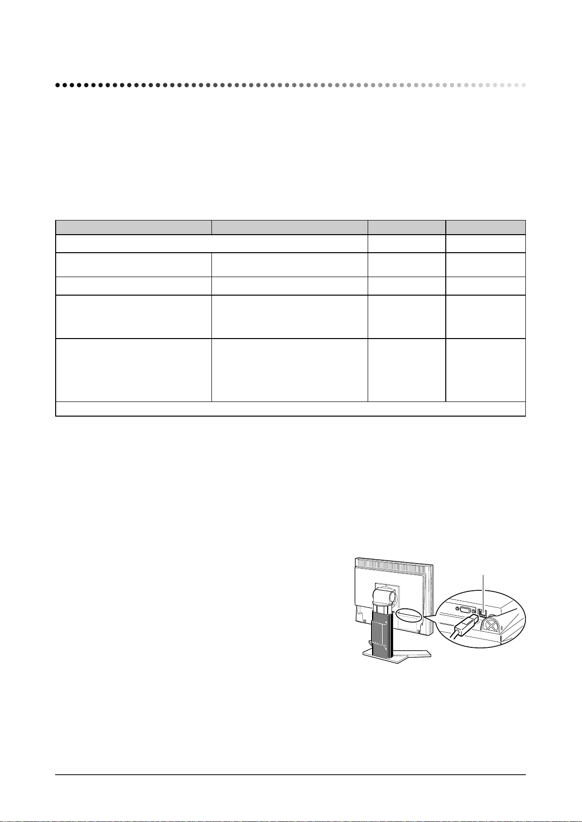
To adjust the monitor using ScreenManager Pro for LCD, connect a PC to the monitor with the supplied USB cable.
[Connection]
(1) Connect the USB port (downstream) of a USB compatible PC (or other USB hub) and the monitor’s USB port
(upstream) with the supplied USB cable.
(2) The USB function is set up automatically upon connection of the USB cable.
Upstream
Chapter 2 Settings and Adjustments
10
Page 13
2-2 Screen Adjustment
Digital Input
When digital signals are input, images are displayed correctly based on the
preset data of the monitor.
Analog Input
The monitor screen adjustment is used to suppress fl ickering of the screen or
adjust screen position and screen size correctly according to the PC to be used.
To use the monitor comfortably, adjust the screen when the monitor is set up for
the fi rst time or when the settings of the PC in use are updated.
The auto-adjustment function works in the following cases:
• When a signal is input into the monitor for the fi rst time
• When a signal is input into the monitor for the fi rst time after the
resolution or refresh rate of input signals is changed
[Adjustment Procedure]
Automatic Adjustment
To adjust screen automatically [Screen]
1
(1) Choose
.
(2) Choose <Execute>, and Press .
(3) Flickering, screen position, and screen size are corrected by the auto-
adjustment function.
<Screen> from the <Auto Adjustment> menu, and press
Attention
• Wait 20 minutes or more from
monitor power on before starting
adjustments.
NOTE
• Use “Screen Adjustment Program” on
the supplied EIZO LCD Utility Disk.
Attention
• This function works correctly when
an image is fully displayed over the
Windows or Macintosh display area.
It does not work properly when an
image is displayed only on a part of
the screen (DOS prompt window, for
example) or when a black background
(wallpaper, etc.) is in use.
• This function does not work correctly
with some graphics boards.
• “Auto in Progress” appears on the
screen during auto adjustment.
If satisfactory adjustment cannot be obtained with the autoadjustment function, perform the adjustment following the
procedure below. When the screen is displayed correctly, go to step
4 “Range Adjustment”.
Advanced Adjustment
Run the Screen Adjustment Program.
2
Load the EIZO LCD Utility Disk on the PC, and start the Screen
Adjustment Program compatible with the PC in use.
After the program starts up, perform the adjustment in step 3 following the
instructions of the program.
NOTE
• For how to start the Screen
Adjustment Program, refer to
“readme.txt” or the “Readme” fi le.
When you are using a Windows PC,
you can run the program directly from
the start menu of the disk.
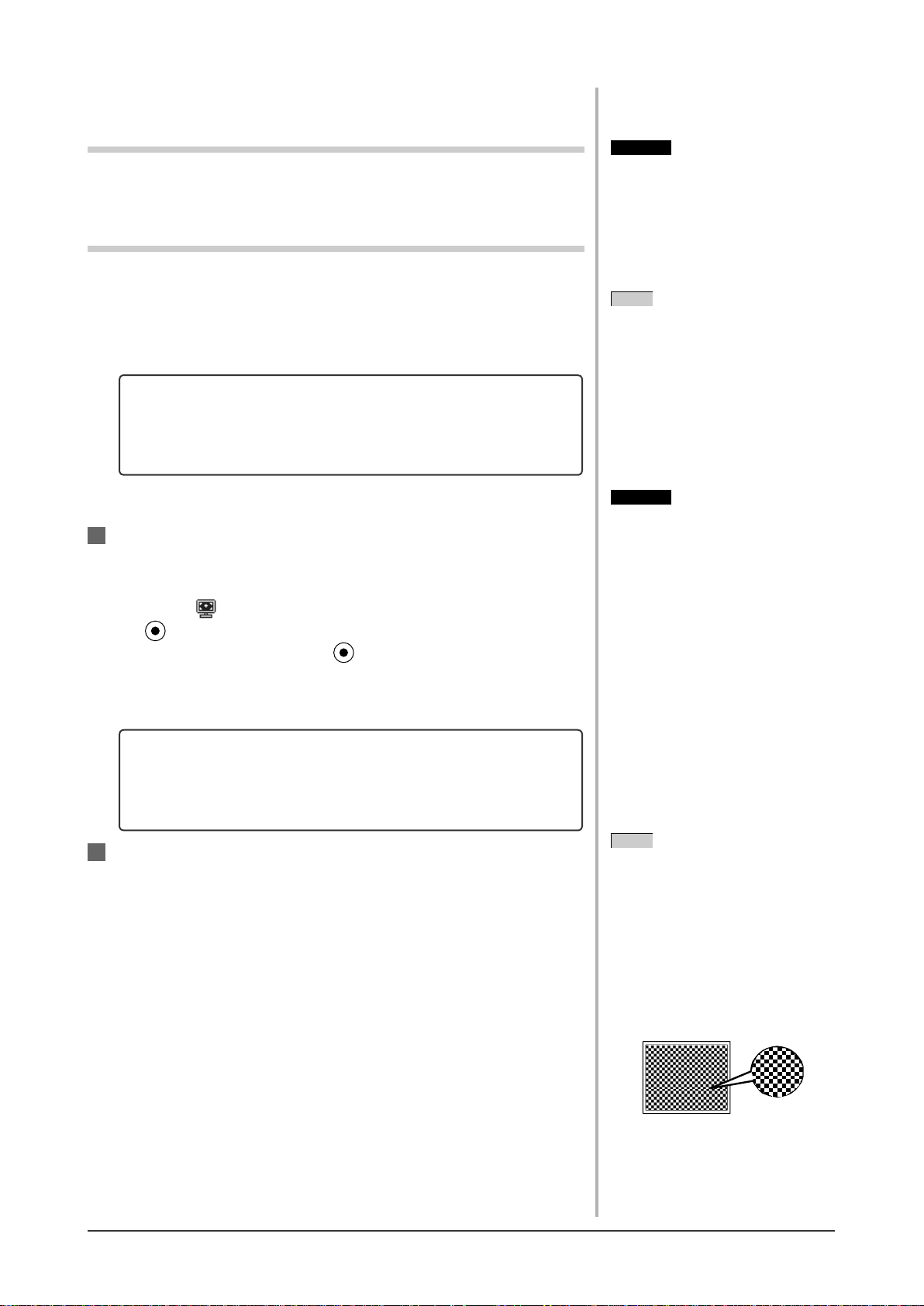
• If no adjustment program is available
for your PC, display a checkerboard
pattern on the screen (see below) and
go to the following steps.
Chapter 2 Settings and Adjustments
11
Page 14
Perform advanced adjustments for the following using the
3
<Screen> menu of the Adjustment menu.
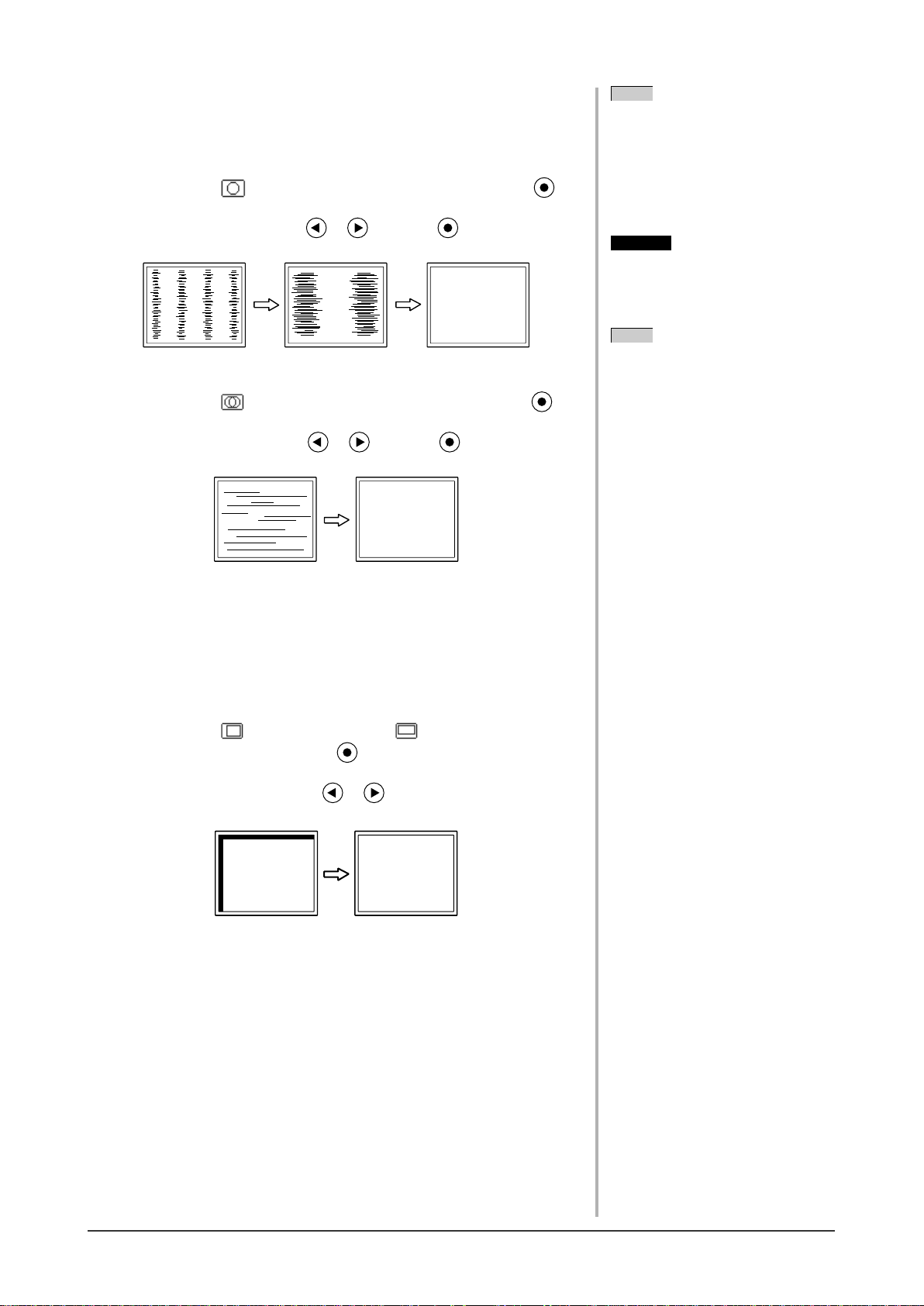
● To eliminate vertical bars [Clock]
(1) Choose <Clock> from the <Screen> menu, and press .
The <Clock> menu appears.
(2) Adjust the clock with or , and press .
The adjustment is completed.
● To remove fl ickering or blurring [Phase]
(1) Choose
The <Phase> menu appears.
<Phase> from the <Screen> menu, and press .
(2) Adjust the phase with or , and press .
The adjustment is completed.
NOTE
• Press the control button slowly so as
not to miss the adjustment point.
• When blurring, fl ickering or bars
appear on the screen after adjustment,
proceed to [Phase] to remove
fl ickering or blurring.
Attention
• Flickering or blurring may not be
eliminated depending on your PC or
graphics board.
NOTE
• When vertical bars appear on the
screen after adjustment, go back to
“To eliminate vertical bars [Clock].”
(Clock → Phase → Position)
● To correct screen position
[Horizontal Position], [Vertical Position]
Since the number of pixels and the pixel positions are fi xed on
the LCD monitor, only one position is provided to display images
correctly. The position adjustment is made to shift an image to the
correct position.
(1) Choose <Hor. Position> and or <Ver. Position> from the
<Screen> menu, and press .
The <Hor. Position> or <Ver. Position> menu appears.
(2) Adjust the position with or to display the image properly
in the display area of the monitor.
Chapter 2 Settings and Adjustments
12
Page 15
Adjust the signal output range
4
● To adjust color gradation automatically [Range Adjustment]
Every color gradation (0 to 255) can be displayed by adjusting the
signal output level.
(1) Choose
press .
(2) Choose <Execute>, and press .
(3) Color gradation is adjusted correctly by the auto-adjustment
function.
The output range is adjusted automatically to display images with the
maximum color gradation.
All the adjustments using the “Screen Adjustment Program” are completed.
<Range> from the <Auto Adjustment> menu, and
Chapter 2 Settings and Adjustments
13
Page 16
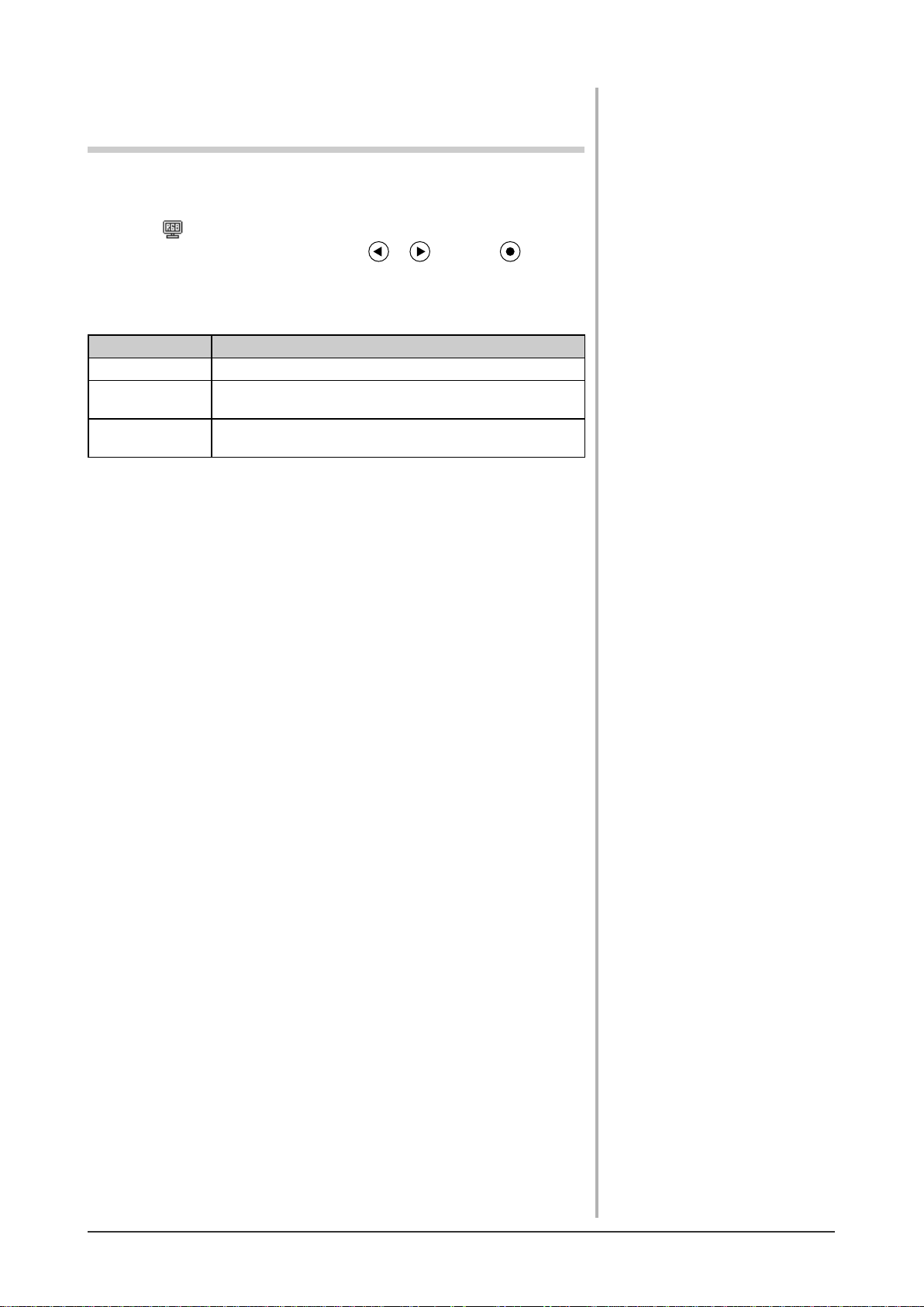
2-3 Color Adjustment
Simple adjustment [FineContrast mode]
This function allows you to select the best display mode for monitor brightness,
etc.
(1) Choose <Color Mode> from the <Color> menu.
(2) Choose [Custom], [sRGB] or [Text] with or , and press .
●
FineContrast Mode
An appropriate display mode is selectable out of three modes.
Mode Purpose
Custom Available for making desired setting.
sRGB
Text
Suitable for color matching with sRGB compatible
peripherals.
Suitable for displaying texts for word processing or
spreadsheets.
Chapter 2 Settings and Adjustments
14
Page 17
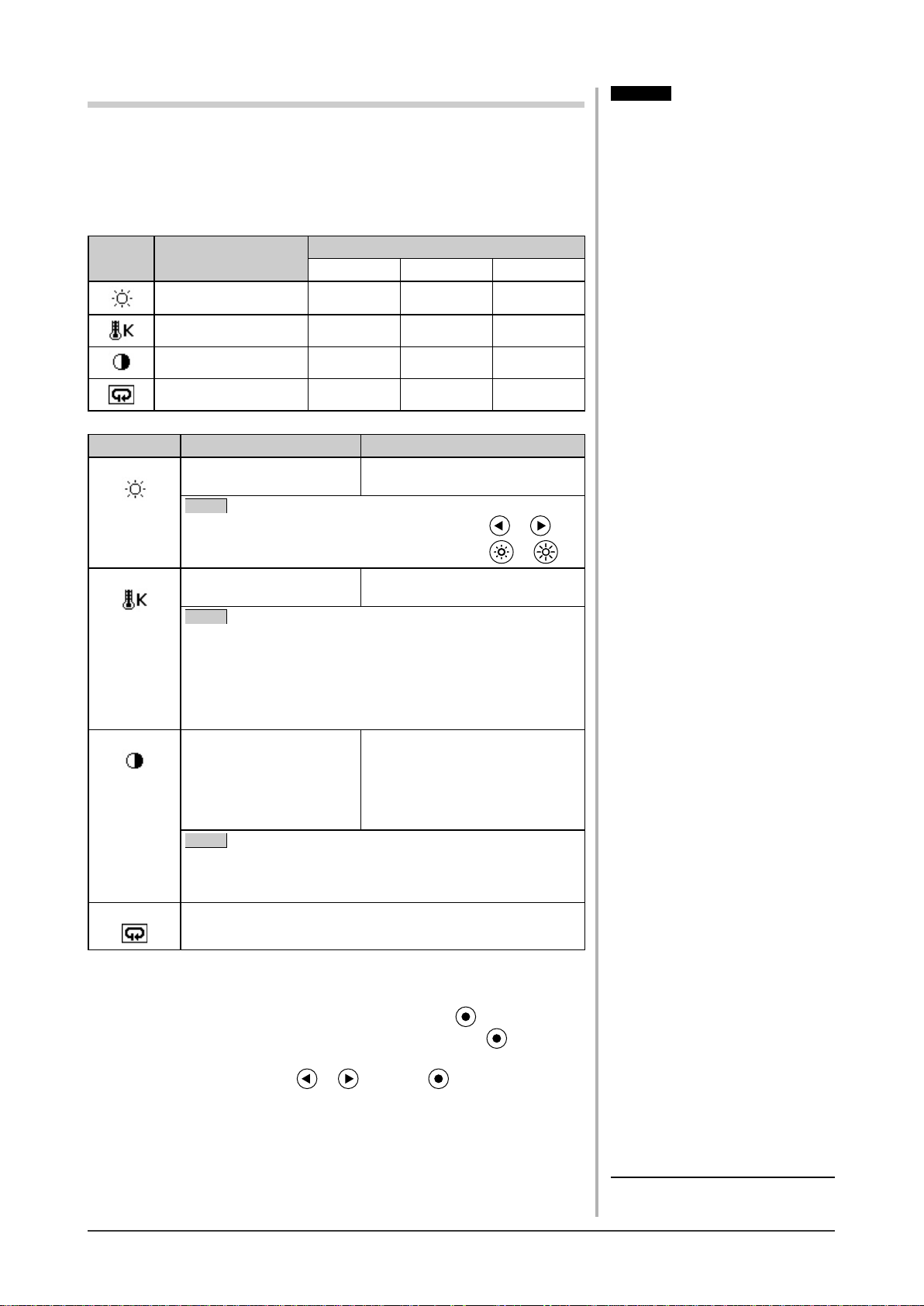
Advanced Adjustments [Adjustment menu]
Independent setting and saving of color adjustment are available for each
FineContrast mode.
●
To select an appropriate mode for images
: Adjustment/setting available −: Factory setting
✓
Icon Function
Brightness
Temperature
Gain
Reset
Menu Description Adjustment range
Brightness
To adjust the full screen
brightness as desired
NOTE
• You can also adjust the brightness by pressing or *1.
• You can also adjust the brightness by pressing
Custom sRGB Text
FineContrast mode
✓✓✓
✓
✓
✓
0 to 100%
−
✓
−−
−
✓
or *2.
Attention
• Perform [Range Adjustment] before
starting color adjustment for analog
input signals.
Refer to “To adjust color gradation
automatically” on page 13.
• The FineContrast mode cannot be
changed during color adjustment. Set
the FineContrast mode in advance on
the color mode screen.
• Wait 20 minutes or more from
monitor power on before starting the
color adjustment.
• Choose [Reset] from the Color menu
to revert to the default setting (factory
setting) of the color tone of the
FineContrast mode selected.
• The same image may be seen in
different colors on multiple monitors
due to their monitor-specifi c
characteristics. Make fi ne color
adjustment visually when matching
colors on multiple monitors.
• Adjustable functions vary depending
on the type of FineContrast mode.
Temperature
Gain
Reset
●
To set/adjust color
To select a color
temperature
NOTE
• The values shown in the Kelvin (K) are available only as
reference.
• While color temperature is adjusted, <Gain> is adjusted
automatically according to the color temperature.
• When <Gain> is set, color temperature setting is disabled,
and is set to “OFF”.
To adjust red, green, and
blue to a desired color tone
respectively
NOTE
• Values shown in percentage are available only as reference.
• The <Temperature> setting invalidates this setting. The
<Gain> setting varies with color temperature.
To reset the color settings of the selected FineContrast mode to
the default settings.
“OFF,” “5000K,” “6500K,” or
“9300K”
0 to 100%
Adjust the respective brightness of
red/green/blue to make a desired
color tone. Display an image with
white or gray background for
adjustment.
(1) Choose <Color> from the Adjustment menu, and press .
(2) Select a desired function from the <Color> menu, and press .
The selected function menu appears.
(3) Adjust the selected item with or , and press .
The adjustment is completed.
*1 :Speaker applied model
2
:Speaker non-applied model
*
Chapter 2 Settings and Adjustments
15
Page 18
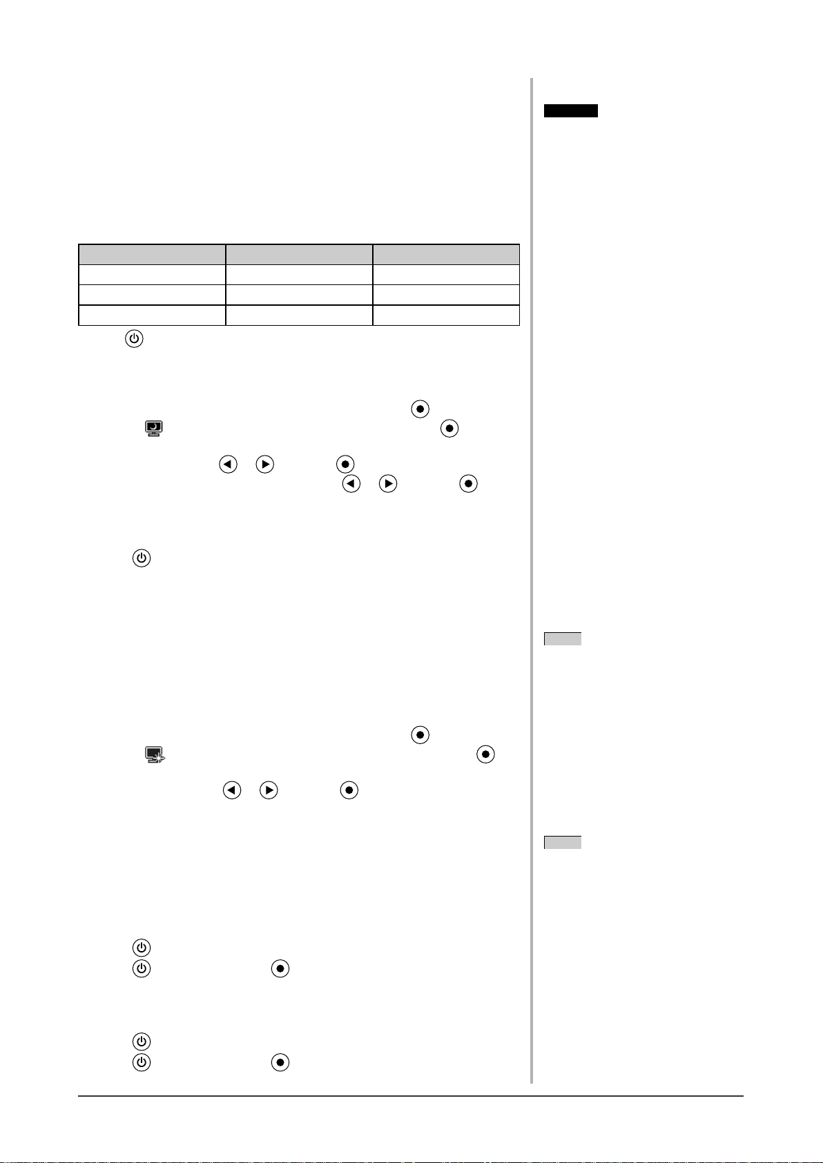
2-4 Off Timer Settings
●
To set monitor power-off time [Off Timer]
This function allows the monitor to automatically turn off after a specifi ed time
has passed. This function serves to reduce afterimages caused when the monitor
screen is left on for a long time period without use. Use this function when an
image is displayed throughout the day.
[Off Timer System]
Timer Monitor Power Indicator
ON time (1H - 23H) Operating Blue
Last 15 min. in “ON time” Advance Notice*
“ON time” expired Power Off Off
*1 When is pressed during the advance notice period, the monitor continues to operate for
additional 90 minutes. Extension of operation time can be set without limitation.
[Procedure]
(1) Choose <Others> from the Adjustment menu, and press .
(2) Choose <Off Timer> from the <Others> menu, and press .
The <Off Timer> menu appears.
(3) Select “Enable” with or , and press .
(4) Set a monitor ON time (1 to 23 hours) with or , and press .
The Off Timer setting is completed.
1
Flashing blue
Attention
• The Off Timer functions even in the
power saving mode, but the advance
notice is disabled. The monitor power
is turned off without advance notice.
[Resumption Procedure]
Press .
2-5 Power Indicator/EIZO Logo Display
Setting
●
To turn off the Power indicator while a screen is displayed
[Power Indicator Setting]
This function enables to turn off the Power indicator (blue) while a screen is
displayed.
(1) Choose <Others> from the Adjustment menu, and press
(2) Choose
The <Power Indicator> menu appears.
<Power Indicator> from the <Others> menu, and press .
(3) Select “Disable” with or , and press .
The Power Indicator setting is completed.
●
To display EIZO logo [EIZO Logo Hiding Function]
When this unit is turned on, the EIZO logo appears at the center of the screen.
Selection to display or not to display the logo is available with this function.
[Procedure]
(1) Press to power off the unit.
(2) Press
The EIZO logo does not appear on the screen.
again while pressing .
.
NOTE
• The Power indicator lights up at
power on with the default setting.
NOTE
• The logo appears with the default
setting.
[Resetting]
(1) Press
to power off the unit.
(2) Press again while pressing .
The logo appears again.
Chapter 2 Settings and Adjustments
16
Page 19
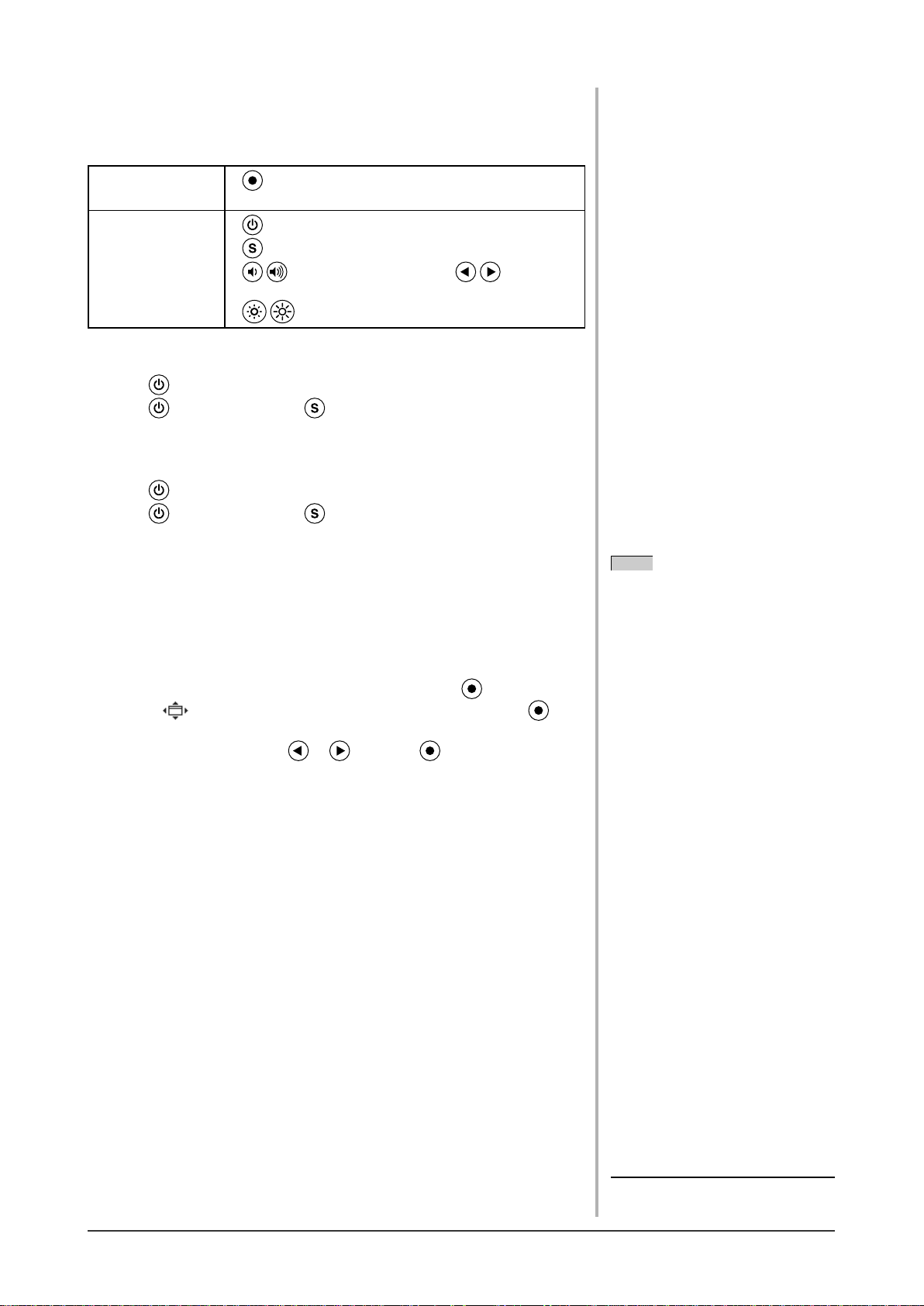
2-6 Locking Buttons
●
To lock operation [Adjustment Lock]
This function locks the buttons to retain the status adjusted or set once.
Buttons that can be
locked
Buttons that cannot
be locked
[Procedure]
(1) Press
(2) Press
The screen is displayed with the adjustment lock.
to turn off the unit.
again while pressing .
[Unlocking]
(1) Press
(2) Press
The screen is displayed with the adjustment lock released.
to turn off the unit.
again while pressing .
(Enter button) Adjustments/settings using
•
Adjustment menu
(Power button)
•
(Input signal selection button)
•
•
control button)*
• (Brightness control button)*
(Volume control button) or
1
(Brightness
2
2-7 Setting Adjustment menu Display
●
To update menu settings [Menu Position]
Menu Position
Adjust the menu position using the following procedure.
(1) Choose <Others> from the Adjustment menu, and press .
(2) Choose
The <Menu Position> menu appears.
(3) Select a menu position with or , and press .
The menu position setting is completed.
<Menu Position> from the <Others> menu, and press .
NOTE
• Five positions (center/ upper right/
lower right/ upper left/ lower left) can
be selected.
*1 :Speaker applied model
2
*
:Speaker non-applied model
Chapter 2 Settings and Adjustments
17
Page 20
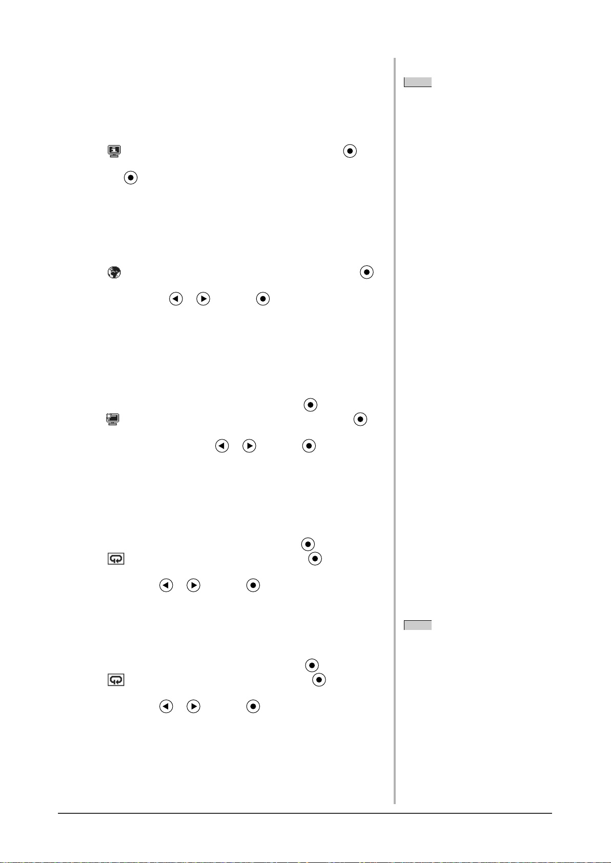
2-8 Viewing Information/Setting Language
●
To check viewing information, usage time, etc.
[Information]
This function allows you to check viewing information, model name, serial
number, and usage time of the monitor.
NOTE
• The usage time is not always “0”
when you purchase the monitor due
to factory inspection.
(1) Choose
The <Information> menu appears.
(2) Then, press to check viewing information, etc.
●
To set a language to be displayed [Language]
Select the Adjustment menu language.
Selectable languages
English/German/French/Spanish/Italian/Swedish/Mandarin/Cantonese/Japanese
(1) Choose <Language> menu from the Adjustment menu, and press .
The <Language> menu appears.
(2) Select a language with or , and press .
The language setting is completed.
<Information> from the Adjustment menu, and press .
2-9 Setting BrightRegulator
●
[BrightRegulator] to set “Enable” or “Disable” for
BrightRegulator.
(1) Choose <Others> from the Adjustment menu, and press .
(2) Choose < BrightRegulator> from the <Others> menu, and press .
The BrightRegulator setting window appears.
(3) Select “Enable” or “Disable” with or , and press .
The BrightRegulator setting is completed.
2-10 Resumption of Default Setting
●
To reset color adjustment [Reset]
Resume the default settings (factory settings) for color adjustment.
(1) Choose <Color> from the Adjustment menu, and press .
(2) Choose
The <Reset> menu appears.
(3) Select <Reset> with or , and press .
The reset operation is completed.
●
To reset all settings [Reset]
Reset all adjustments/settings to the factory default settings.
(1) Choose <Others> from the Adjustment menu, and press .
(2) Choose
The <Reset> menu appears.
(3) Select <Reset> with or , and press .
The reset operation is completed.
<Reset> from the <Color> menu, and press .
<Reset> from the <Others> menu, and press .
NOTE
• For default settings, refer to “Main
default settings (factory settings)” on
page 25.
Chapter 2 Settings and Adjustments
18
Page 21
Chapter 3 Connecting Cables
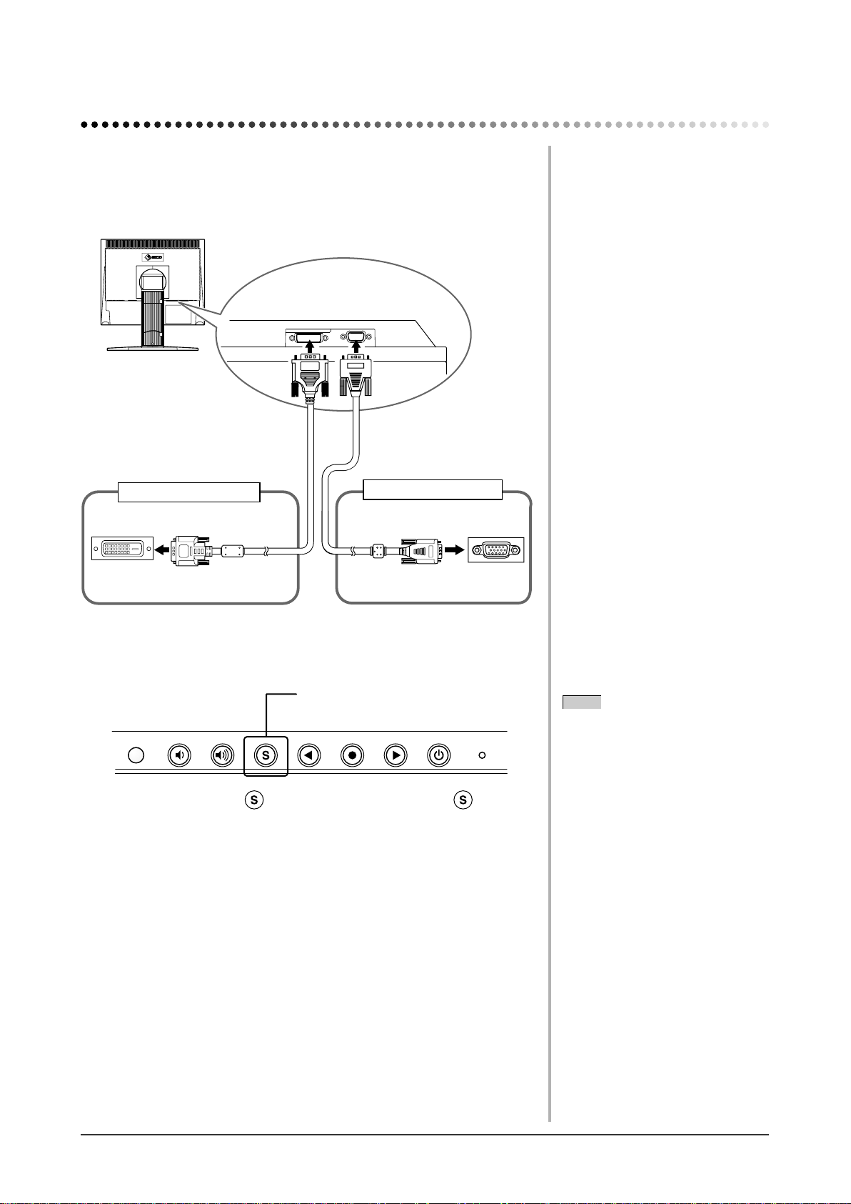
3-1 Connecting Two PCs to the Monitor
Two PCs can be connected to the monitor through the DVI-D and the D-Sub
mini 15 pin connector on the back of the monitor.
Connection examples
D-sub mini
15-pin Connector
Signal cable
MD-C87
To PC 2
D-sub mini 15-pin
Connector
DVI-D connector
To PC 1
Signal cable
(Digital) FD-C39
DVI-D connector
Selecting input signal
Input Signal Selection button
Switch the input signal with . Input signal switches each time is pressed.
When the signal is switched, the active signal type (Analog or Digital) appears
at the top right corner of the screen for two seconds.
NOTE
• The monitor recognizes the connector
through which PC signals are input.
When either PC is turned off or enters
the power-saving mode, the monitor
automatically displays signals of
another PC.
Chapter 3 Connecting Cables
19
Page 22
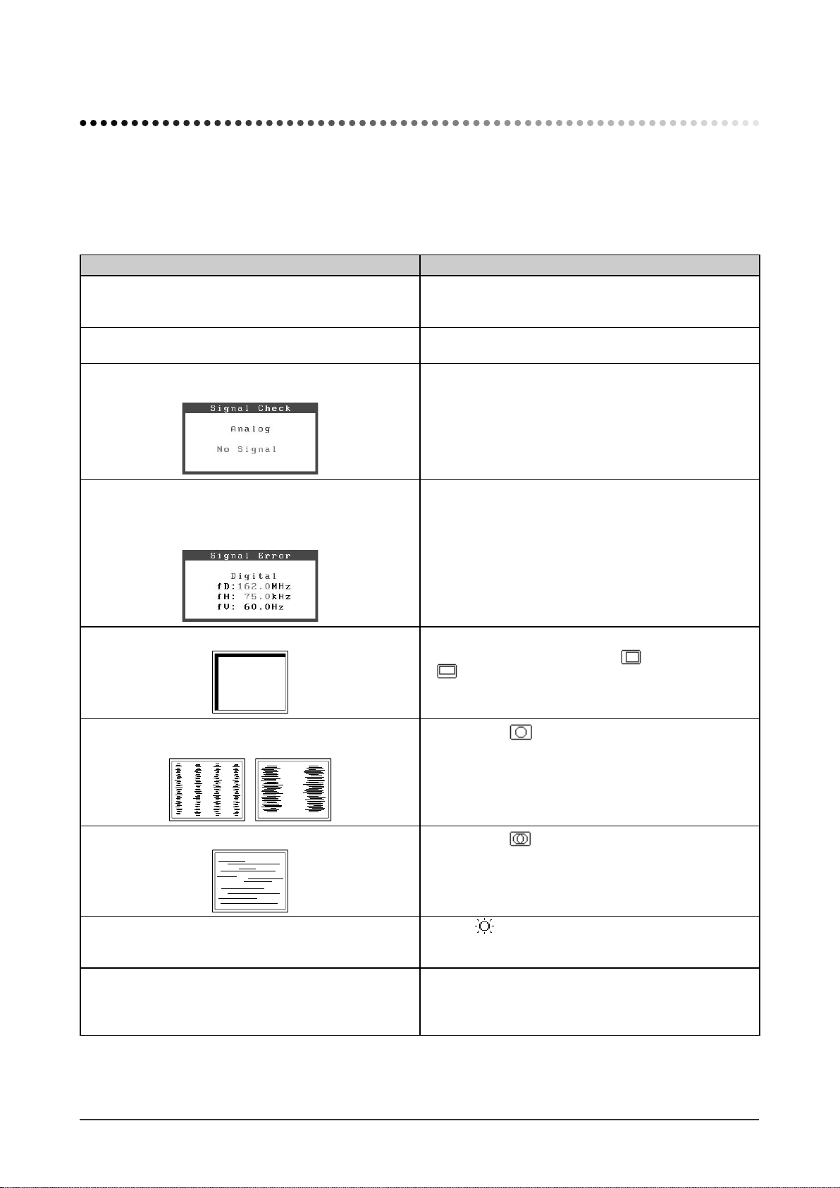
Chapter 4 Troubleshooting
If a problem still remains after applying the suggested remedies, contact your local dealer.
• No-picture problems → See No.1 - No.2.
• Imaging problems → See No.3 - No.11.
• Other problems → See No.12 - No.13.
Problems Possible cause and remedy
1. No picture
• Power indicator does not light.
• Power indicator is lighting blue.
• Power indicator is lighting orange.
2. The message below appears.
• This message appears when no signal is input.
• Check whether the power cord is connected correctly. If
the problem persists, turn off the monitor, and then turn it
on again a few minutes later.
• Check Gain setting. (see page 15)
• Operate the mouse or keyboard.
This message appears when the signal is not input
correctly even when the monitor functions properly.
• The message shown left may appear, because some
PCs do not output the signal soon after power-on.
• Check whether the PC is turned on.
• Check whether the signal cable is connected properly.
• The message below shows that the input signal is
out of the specifi ed frequency range. (Such signal
frequency is displayed in red.)
Example:
3. Display position is incorrect.
4. Vertical bars appear on the screen or a part of the
image is fl ickering.
5. Whole screen is fl ickering or blurring.
• Select an appropriate display mode using the graphics
board’s utility software. Refer to the manual of the
graphics board for details.
• Adjust image position so that it is displayed properly
within the display area using the <Hor.Position> and
<Ver.Position> adjustment.
• If the problem persists, use the graphics board’s utility
software if available to change the display position.
• Adjust using <Clock> from <Screen> menu at the
Adjustment menu.
• Adjust using <Phase>.
6. The screen is too bright or too dark.
7. Afterimages appear. • Use a screen saver or off timer function for a long-time
Chapter 4 Troubleshooting
20
• Adjust
has a fi xed life span. When the screen becomes dark or
begins to fl icker, contact your local dealer.)
image display.
• Afterimages are particular to LCD monitors. Avoid
displaying the same image for a long time.
<Brightness>. (The LCD monitor backlight
Page 23
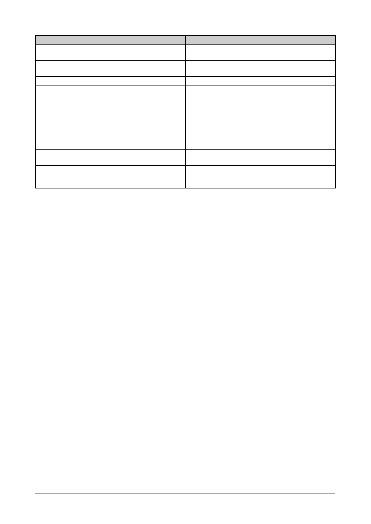
Problems Possible cause and remedy
8. Green/red/blue/white dots or defective dots remain
on the screen.
9. Interference patterns or fi ngerprints remain on the
screen.
10. The Main menu of Adjustment menu does not start. • Check for Adjustment Lock function.
11. The auto-adjustment function does not work
correctly.
12. Frequency does not change after the utility disk is
installed on Windows 98/Me/2000/XP.
13. No audio output*
*1: Speaker applied model.
1
• This is due to LCD panel characteristics and is not a
failure.
• Leave the monitor with a white screen. The symptom
may disappear.
• This function does not work when digital signal is input.
• This function works correctly when an image is fully
displayed over the Windows or Macintosh display area.
It does not work properly when an image is displayed
only on a part of the screen (DOS prompt window, for
example) or when a black background (wallpaper, etc.) is
in use.
This function does not work correctly with some graphics
boards.
• Change the input signal frequency using the graphics
board’s utility software.
• Check whether <Volume> is set to “0”.
• Check the settings of the PC and the audio playback
software.
Chapter 4 Troubleshooting
21
Page 24
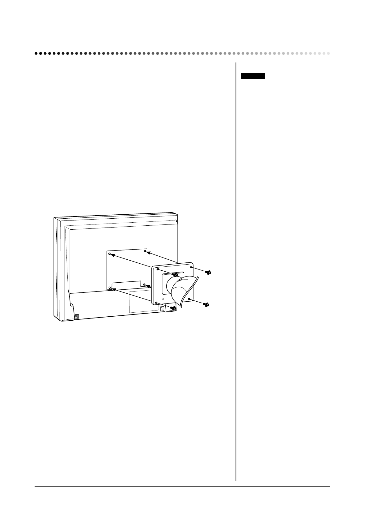
Chapter 5 Reference
5-1 Attaching an Arm (Option)
The stand can be removed and replaced with an arm (or another stand) to be
attached to the monitor. Use an arm or stand of EIZO option.
[Attaching]
Lay the LCD monitor on a soft cloth spread over on a stable
1
surface with the panel surface facing down.
Remove the stand. (Prepare a screwdriver.)
2
Unscrew the four screws securing the unit and the stand with the
screwdriver.
Attach the monitor to the arm or stand.
3
Secure the monitor to the arm or stand using the screws specifi ed in the
user’s manual of the arm or stand.
Attention
• When attaching an arm or stand,
follow the instructions of their user’s
manual.
• When using another manufacturer’s
arm or stand, confi rm the following in
advance and select one conforming to
the VESA standard. Use the M4 × 12
screws supplied with this monitor.
– Clearance between the screw holes:
100 mm × 100 mm
– Thickness of plate: 2.6 mm
– Strong enough to support weight of
the monitor unit (except the stand)
and attachments such as cables.
• Attach an arm or stand to meet the
following tilt angles of the monitor.
– Up 60 degrees, down 45 degrees
– Up 45 degrees, down 45 degrees
(vertical display, 90 degrees
clockwise)
• Connect the cables after attaching an
arm.
Chapter 5 Reference
22
Fixing screws: M4 × 12mm 4 pcs
Page 25
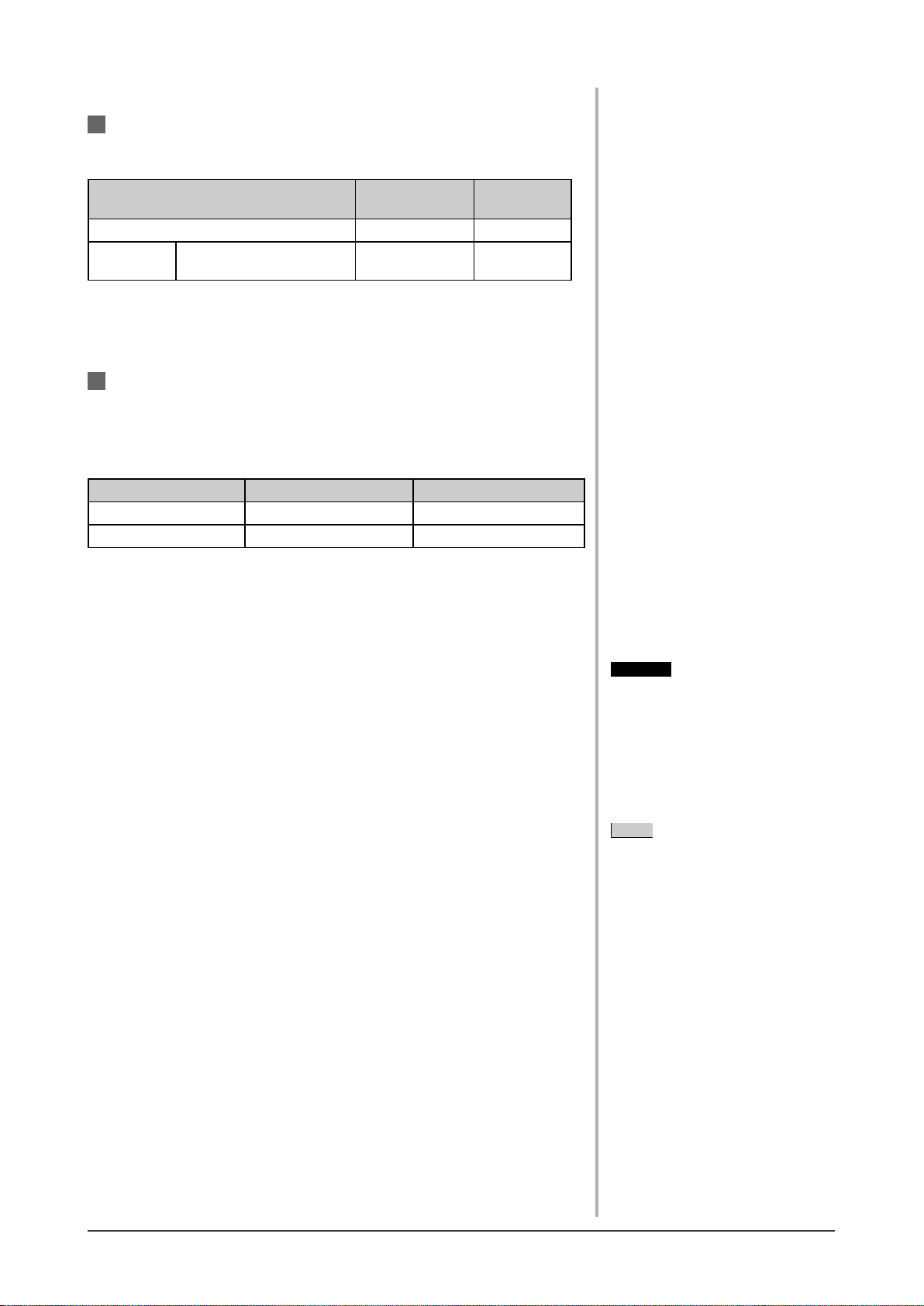
5-2 Power Saving Mode
Analog input
This monitor complies with the VESA DPMS standard.
[Power Saving System]
PC Monitor
Operating Operating Blue
Power
saving
STAND-BY
SUSPENDED OFF
Power saving Orange
[Resumption Procedure]
(1) Operate the mouse or keyboard to resume the normal screen.
Digital input
This monitor complies with the DVI DMPM standard.
[Power Saving System]
The monitor enters the power saving mode in fi ve seconds in connection with
the PC setting.
PC Monitor PowerIndicator
Operating Operating Blue
Powersaving Power saving Orange
Power
Indicator
[Resumption Procedure]
• Operate the mouse or keyboard to resume the normal screen from the PC’s
power saving mode.
5-3 Cleaning
Clean the monitor periodically to keep the monitor clean and extend its life.
Cabinet
Clean the cabinet with a soft cloth dampened with little mild detergent.
LCD Panel
• Clean the LCD panel with a soft cloth such as cotton cloth or lens cleaning
paper.
• Remove persistent stains gently with a cloth dampened with little water, and
then clean the LCD panel again with a dry cloth for better fi nishing.
Attention
• Never use any solvents or chemicals,
such as thinner, benzene, wax,
alcohol, and abrasive cleaner, which
may damage the cabinet or LCD
panel.
NOTE
• Optional ScreenCleaner is
recommended for cleaning the panel
surface.
Chapter 5 Reference
23
Page 26
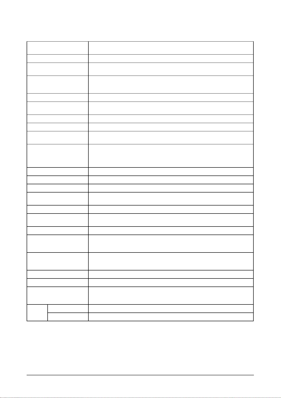
5-4 Specifi cations
LCD Panel 19-inch (48 cm) TFT color LCD with anti-glare hard coating
Viewing angle: Vertical 178°, Horizontal 178° (CR: 10 or more)
Dot Pitch 0.294 mm
Horizontal Scan Frequency Analog: 24.8 - 80 kHz (Automatic)
Digital: 31 - 64 kHz
Vertical Scan Frequency Analog: 50 - 75 Hz (Automatic)
Digital: 59 - 61 Hz
(VGA TEXT: 69 - 71 Hz)
Resolution 1280 dots × 1024 lines
Max. Dot Clock Analog: 135 MHz
Digital: 108 MHz
Max. Display Colors 16.77 million colors
Display Area (H × V) 376.3 mm (14.81 inch) × 301.0 mm (11.85 inch)
Power Supply 100 - 120 VAC ±10% 50/60 Hz, 0.65 A
200 - 240 VAC ±10% 50 Hz, 0.4 A
*1
Power Consumption
Maximum (usually): 38W (speaker not working) / 40W (speaker working)
*2
Maximum (usually): 38W
Power saving mode: 1 W or less (for single signal input with no line input connector
connected)
Input Signal Connectors DVI-D connector, D-sub mini 15-pin connector
Analog Input Signal (Sync) H/V Separate, TTL, positive/negative
Analog Input Signal (Video) Analog, positive (0.7 Vp-p/75 Ω)
Digital Signal Transmission
TMDS (Single Link)
System
Video Signal Memory Analog signal: 26 (preset: 21)
Audio output
*1
Speaker output: 0.3W + 0.3W (16Ω, THD: 10% or less)
Headphone output: 2mW + 2mW
Plug & Play VESA DDC 2B/EDID structure 1.3
Dimensions (including stand)
392.4(15.4) × 404.9(15.9) - 504.9(19.9) × 205(8.1)
(Width) × (Height) × (Depth)
mm (inch)
Dimensions (main unit)
392.4(15.4) × 330.8(13.0) × 55(2.17)
(Width) × (Height) × (Depth)
mm (inch)
Mass (including stand) 6.8 kg (15.0 lbs)
Mass (Main unit) 4.7 kg (10.4 lbs)
Environmental Conditions Operating temperature: 0 °C - 35 °C (32 °F - 95 °F)
Storage temperature: –20 °C - 60 °C (-4 °F - 140 °F)
Relative humidity: 30% - 80% (no condensation)
Standard Rev. 2.0 compliant
USB
Port Upstream port × 1
*1
Model for built-in speaker
*2
Model for no mount speaker
Chapter 5 Reference
24
Page 27
Main default settings (factory settings)
BrightRegulator Enable
FineContrast Mode Custom
Off Timer Disabled
Language English
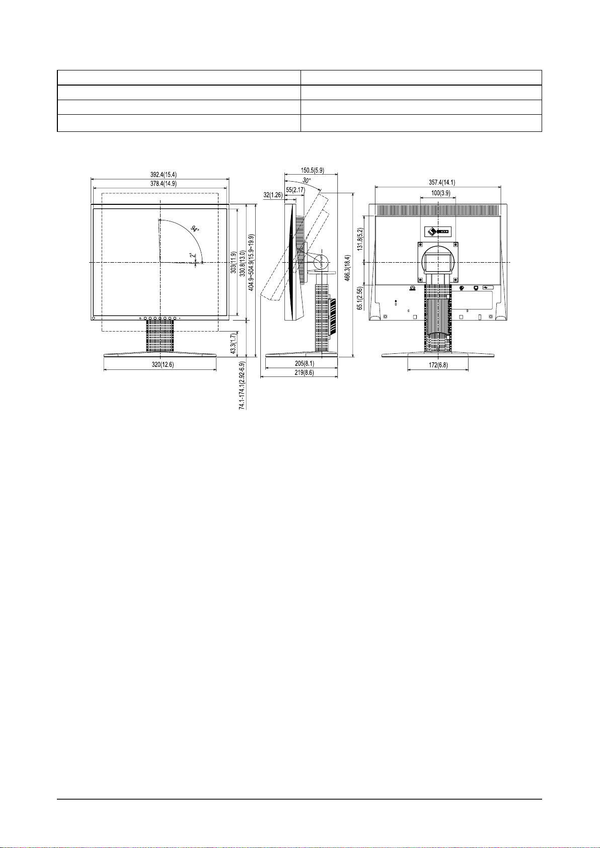
Outside Dimensions
unit : mm (inch)
Chapter 5 Reference
25
Page 28
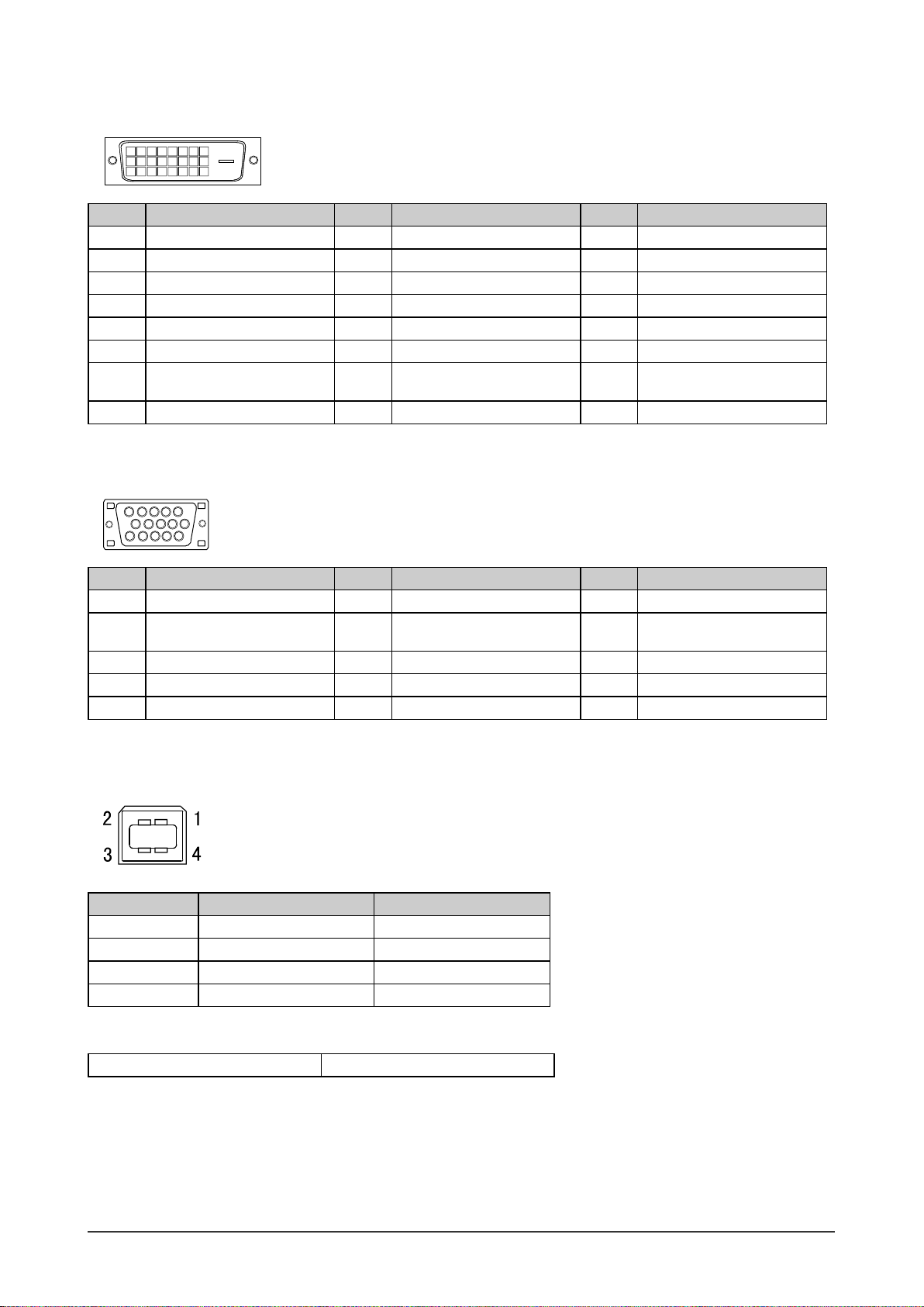
Connector Pin Assignment
• DVI-D connector
Pin No.
234
1
10
9
11
19
18 22 23
17
8
7
6
5
12
14 15
16
13
24
20
21
Signal
Pin No.
Signal
Pin No.
Signal
1 TMDS Data 2- 9 TMDS Data1- 17 TMDS Data02 TMDS Data 2+ 10 TMDS Data1+ 18 TMDS Data0+
3 TMDS Data2/4 Shield 11 TMDS Data1/3 Shield 19 TMDS Data0/5 Shield
4 NC* 12 NC* 20 NC*
5 NC* 13 NC* 21 NC*
6 DDC Clock (SCL) 14 +5V Power 22 TMDS Clock shield
7 DDC Data (SDA) 15 Ground (return for +5V,
23 TMDS Clock+
Hsync and Vsync)
8 NC* 16 Hot Plug Detect 24 TMDS Clock-
(NC*: No Connection)
• D-sub mini 15-pin connector
3
1
2
4
5
10
8
9
7
15
Pin No.
1 Red 6 Red ground 11 Ground
2 Green 7 Green ground 12 Data (SDA)
6
11
1314
12
Signal
Pin No.
Signal
Pin No.
Signal
3 Blue 8 Blue ground 13 H. Sync
4 Ground 9 NC* 14 V. Sync
5 NC* 10 Ground 15 Clock (SCL)
• USB port
Upstream
Contact No. Signal Remarks
1 VCC Cable power
2 – Data Serial data
3 + Data Serial data
4 Ground Cable ground
Option List
Cleaning Kit EIZO ScreenCleaner
(NC*: No Connection)
Chapter 5 Reference
26
Page 29

5-5 Glossary
Clock
The analog input monitor needs to reproduce a clock of the same frequency as the dot clock of the graphics system in
use, when the analog input signal is converted to a digital signal for image display.
This is called clock adjustment. If the clock pulse is not set correctly, some vertical bars appear on the screen.
DVI (Digital Visual Interface)
DVI is a digital interface standard. DVI allows direct transmission of the PC’s digital data without loss.
This adopts the TMDS transmission system and DVI connectors. There are two types of DVI connectors. One is
a DVI-D connector for digital signal input only. The other is a DVI-I connector for both digital and analog signal
inputs.
DVI DMPM (DVI Digital Monitor Power Management)
DVI DMPM is a digital interface power-saving function. The “Monitor ON (operating mode)” and “Active Off
(power-saving mode)” are indispensable for DVI DMPM as the monitor’s power mode.
Gain
This is used to adjust each color parameter for red, green and blue. An LCD monitor displays the color by the light
passing through the panel color fi lter. Red, green and blue are the three primary colors. All the colors on the screen
are displayed by combining these three colors. The color tone can be changed by adjusting the light intensity (volume)
passing through each color’s fi lter.
Phase
Phase means the sampling timing to convert the analog input signal to a digital signal. Phase adjustment is made to
adjust the timing. It is recommended that phase adjustment be made after the clock is adjusted correctly.
Resolution
The LCD panel consists of numerous pixels of specifi ed size, which are illuminated to form images. The monitor
consists of 1280 horizontal pixels and 1024 vertical pixels. At a resolution of 1280 × 1024, all pixels are illuminated
as a full screen (1:1).
sRGB (Standard RGB)
International standard for “color reproduction and color space” among peripheral devices (such as monitors, printers,
digital cameras, scanners). sRGB allows Internet users to closely match colors as a simple color matching means for
the Internet use.
Temperature
Color temperature is a method to measure the white color tone, generally indicated in degrees Kelvin. The screen
becomes reddish at a low temperature, and bluish at a high temperature, like the fl ame temperature.
5000K: Slightly reddish white
6500K: Warm white like paper white
9300K: Slightly bluish white
TMDS (Transition Minimized Differential Signaling)
A signal transmission system for digital interface.
VESA DPMS (Video Electronics Standards Association - Display Power Management Signaling)
VESA provides the standardization of signals from PC (graphics board) for power saving of PC monitors. DPMS
defi nes the signal status between PC and monitor.
Chapter 5 Reference
27
Page 30
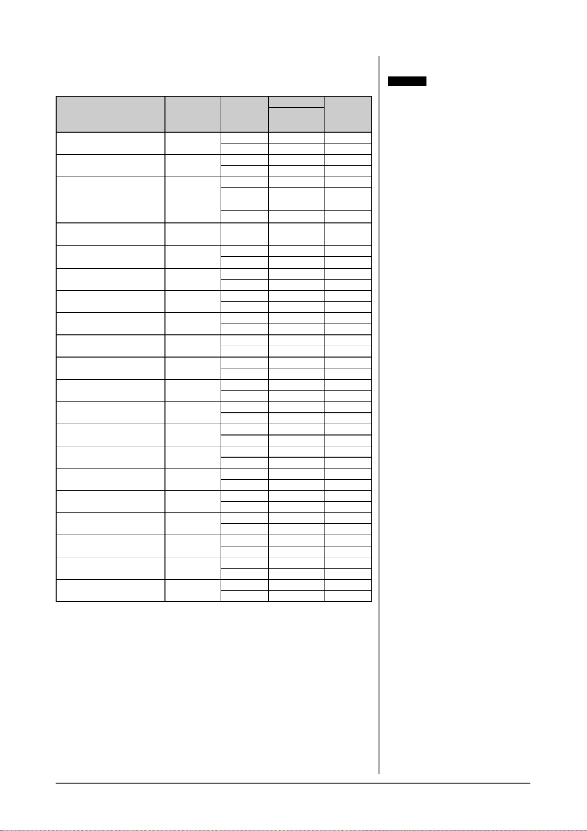
5-6 Preset Timing
The following table shows factory preset video timing.
Mode Dot clock
VGA 640×480@60Hz 25.2 MHz
VGA 720×400@70Hz 28.3 MHz
Macintosh 640×
480@67Hz
Macintosh 832×
624@75Hz
Macintosh 1152×
870@75Hz
Macintosh 1280×
960@75Hz
PC-9801 640×400@56Hz 21.0MHz
PC-9821 640×400@70Hz 25.2 MHz
VESA 640×480@72Hz 31.5 MHz
VESA 640×480@75Hz 31.5 MHz
VESA 800×600@56Hz 36.0 MHz
VESA 800×600@60Hz 40.0 MHz
VESA 800×600@72Hz 50.0 MHz
VESA 800×600@75Hz 49.5 MHz
VESA 1024×768@60Hz 65.0 MHz
VESA 1024×768@70Hz 75.0 MHz
VESA 1024×768@75Hz 78.8 MHz
VESA 1152×864@75Hz 108.0 MHz
VESA 1280×960@60Hz 108.0 MHz
VESA 1280×1024@60Hz 108.0 MHz
VESA 1280×1024@75Hz 135.0 MHz
30.2 MHz
57.3 MHz
100.0 MHz
126.2 MHz
Horizontal 31.47 Negative
Vertical 59.94 Negative
Horizontal 31.47 Negative
Vertical 70.09 Positive
Horizontal 35 Negative
Vertical 66.67 Negative
Horizontal 49.73 Negative
Vertical 74.55 Negative
Horizontal 68.68 Negative
Vertical 75.06 Negative
Horizontal 74.76 Positive
Vertical 74.76 Positive
Horizontal 24.83 Negative
Vertical 56.42 Negative
Horizontal 31.5 Negative
Vertical 70.15 Negative
Horizontal 37.86 Negative
Vertical 72.81 Negative
Horizontal 37.5 Negative
Vertical 75 Negative
Horizontal 35.16 Positive
Vertical 56.25 Positive
Horizontal 37.88 Positive
Vertical 60.32 Positive
Horizontal 48.08 Positive
Vertical 72.19 Positive
Horizontal 46.88 Positive
Vertical 75 Positive
Horizontal 48.36 Negative
Vertical 60 Negative
Horizontal 56.48 Negative
Vertical 70.07 Negative
Horizontal 60.02 Positive
Vertical 75.03 Positive
Horizontal 67.5 Positive
Vertical 75 Positive
Horizontal 60 Positive
Vertical 60 Positive
Horizontal 63.98 Positive
Vertical 60.02 Positive
Horizontal 79.98 Positive
Vertical 75.03 Positive
Frequency
Horizontal: kHz
Vertical: Hz
Polarity
Attention
• Display position may be deviated
depending on the PC connected,
which may require screen adjustment
using Adjustment menu.
• If a signal other than those listed in
the table is input, adjust the screen
using the Adjustment menu. However,
screen display may still be incorrect
even after the adjustment.
• When interlace signals are used, the
screen cannot be displayed correctly
even after screen adjustment using the
Adjustment menu.
Chapter 5 Reference
28
Page 31

Congratulations!
The display you have just purchased carries the TCO’03 Displays label. This
means that your display is designed, manufactured and tested according to
some of the strictest quality and environmental requirements in the world.
This makes for a high performance product, designed with the user in focus
that also minimizes the Impact on our natural environment.
Some of the features of the TCO’03 Display requirements:
Ergonomics
● Good visual ergonomics and image quality in order to improve the working environment for the user
and to reduce sight and strain problems. Important parameters are luminance, contrast, resolution,
refl ectance, colour rendition and image stability.
Energy
● Energy-saving mode after a certain time - benefi cial both for the user and environment
● Electrical safety
Emissions
● Electromagnetic fi elds
● Noise emissions
Ecology
● The products must be prepared for recycling and the manufacturer must have a certifi ed environmental
management system such as EMAS or ISO 14000
● Restrictions on
● chlorinated and brominated fl ame retardants and polymers
● heavy metals such as cadmium, mercury and lead.
The requirements includes in this label have been developed by TCO Development in co-operation with scientists,
experts, users as well as manufacturers all over the world. Since the end of the 1980s TCO has been involved in
infl uencing the development of IT equipment in a more user-friendly direction. Our labeling system with displays
in 1992 and is now requested by users and IT-manufacturers all over the world.
For more information, please visit
www.tcodevelopment.com
Chapter 5 Reference
29
Page 32
For U.S.A. , Canada, etc. (rated 100-120 Vac) Only
FCC Declaration of Conformity
We, the Responsible Party EIZO NANAO TECHNOLOGIES INC.
5710 Warland Drive, Cypress, CA 90630
Phone: (562) 431-5011
declare that the product Trade name: EIZO
Model: FlexScan S1961
is in conformity with Part 15 of the FCC Rules. Operation of this product is subject to the following two
conditions: (1) this device may not cause harmful interference, and (2) this device must accept any
interference received, including interference that may cause undesired operation.
This equipment has been tested and found to comply with the limits for a Class B digital device, pursuant to Part 15
of the FCC Rules. These limits are designed to provide reasonable protection against harmful interference in a
residential installation. This equipment generates, uses, and can radiate radio frequency energy and, if not installed
and used in accordance with the instructions, may cause harmful interference to radio communications. However,
there is no guarantee that interference will not occur in a particular installation. If this equipment does cause harmful
interference to radio or television reception, which can be determined by turning the equipment off and on, the user
is encouraged to try to correct the interference by one or more of the following measures.
* Reorient or relocate the receiving antenna.
* Increase the separation between the equipment and receiver.
* Connect the equipment into an outlet on a circuit different from that to which the receiver is connected.
* Consult the dealer or an experienced radio/TV technician for help.
Changes or modifi cations not expressly approved by the party responsible for compliance could void the user’s
authority to operate the equipment.
Note
Use the attached specifi ed cable below or EIZO signal cable with this monitor so as to keep interference within the
limits of a Class B digital device.
- AC Cord
- Shielded Signal Cable (D-SUB mini 15 pin - D-SUB mini 15 pin, the enclosed signal cable)
- Stereo mini-jack cable (Speaker applied model)
Canadian Notice
This Class B digital apparatus complies with Canadian ICES-003.
Cet appareil numérique de le classe B est comforme à la norme NMB-003 du Canada.
30
Page 33

Hinweise zur Auswahl des richtigen Schwenkarms für Ihren Monitor
Dieser Monitor ist für Bildschirmarbeitsplätze vorgesehen. Wenn nicht der zum Standardzubehör gehörige
Schwenkarm verwendet wird, muss statt dessen ein geeigneter anderer Schwenkarm installiert werden. Bei der
Auswahl des Schwenkarms sind die nachstehenden Hinweise zu berücksichtigen:
Der Standfuß muß den nachfolgenden Anforderungen entsprechen:
a) Der Standfuß muß eine ausreichende mechanische Stabilität zur Aufnahme des Gewichtes vom Bildschirmgerät
und des spezifi zierten Zubehörs besitzen. Das Gewicht des Bildschirmgerätes und des Zubehörs sind in der
zugehörenden Bedienungsanleitung angegeben.
b) Die Befestigung des Standfusses muß derart erfolgen, daß die oberste Zeile der Bildschirmanzeige nicht höher
als die Augenhöhe eines Benutzers in sitzender Position ist.
c) Im Fall eines stehenden Benutzers muß die Befestigung des Bildschirmgerätes derart erfolgen, daß die Höhe der
Bildschirmmitte über dem Boden zwischen 135 – 150 cm beträgt.
d) Der Standfuß muß die Möglichkeit zur Neigung des Bildschirmgerätes besitzen (max. vorwärts: 5°, min. nach
hinten ≥ 5°).
e) Der Standfuß muß die Möglichkeit zur Drehung des Bildschirmgerätes besitzen (max. ±180°). Der maximale
Kraftaufwand dafür muß weniger als 100 N betragen.
f) Der Standfuß muß in der Stellung verharren, in die er manuell bewegt wurde.
g) Der Glanzgrad des Standfusses muß weniger als 20 Glanzeinheiten betragen (seidenmatt).
h) Der Standfuß mit Bildschirmgerät muß bei einer Neigung von bis zu 10° aus der normalen aufrechten Position
kippsicher sein.
Hinweis zur Ergonomie :
Dieser Monitor erfüllt die Anforderungen an die Ergonomie nach EK1-ITB2000 mit dem Videosignal, 1280 ×
1024 RGB analog, 0,7 Vp-p und mindestens 60,0 Hz Bildwiederholfrequenz, non interlaced. Weiterhin wird aus
ergonomischen Gründen empfohlen, die Grundfarbe Blau nicht auf dunklem Untergrund zu verwenden (schlechte
Erkennbarkeit, Augenbelastung bei zu geringem Zeichenkontrast.)
„Maschinenlärminformations-Verordnung 3. GPSGV:
Der höchste Schalldruckpegel beträgt 70 dB(A) oder weniger gemäss EN ISO 7779“
31
Page 34

Recycle Auskunft
Die Rücknahme dieses Produktes nach Nutzungsende übernimmt EIZO in Deutschland zusammen mit dem
Partner eds-r gmbh rucknahmesysteme. Dort werden die Geräte in ihre Bestandteile zerlegt, die dann der
Wiederverwertung zugeführt werden. Um einen Abholtermin zu vereinbaren und die aktuellen Kosten zu erfahren,
benutzen Sie bitte folgende Rufnummer: 02153-73 35 00. Weitere Informationen fi nden Sie auch unter der
Internet-Adresse: http://www.eizo.de.
Recycling Information for customers in Switzerland:
All recycling information is placed in the SWICO’s website.
http://www.swico.ch
Recycling-Information für Kunden in der Schweiz:
Alle Informationen zum Thema Recycling finden Sie auf der Homepage des Brancheverbandes SWICO.
http://www.swico.ch
Renseignements de recyclage pour les clients en Suisse:
Vous trouvez tous les renseignements pour le sujet de recyclage sur la page WEB de I’UNION DE BRAN CHE
SWICO.
http://www.swico.ch
Recycling Information for customers in USA:
All recycling information is placed in the EIZO Nanao Technologies, Inc’s website.
http://www.eizo.com
Återvinnings information för kunder i Sverige:
All information om återvinning finns på Eizo Europe AB:s hemsida:
http://www.eizo.se
32
Page 35
 Loading...