

Page 1
Color LCD Monitor
Touch Panel Color LCD Monitor
日本語
English
中文
한국어
セットアップ マ ニュアル
重 要: ご使用前に必ずこのセットアップマニュアルおよび取扱説明書(CD-ROM内)
をよくお読みになり、正しくお使いください。このセットアップマニュアルは大
切に保管してください。
Setup Manual
Important: Please read this Setup Manual and the User’s Manual stored (on the CD-
ROM) carefully to familiarize yourself with safe and effective usage. Please
retain this manual for future reference.
设定手册
重要事项: 请仔细阅读本设定手册和用户手册(储存在光盘上),以便掌握如何安全、
有效地使用本产品。请保留本手册,以备日后参考。
설치 설명서
중요: 보관된 본 설치 설명서 및 사용 설명서(CD-ROM)를 자세히 읽어서 안전하고
효과적인 사용 방법을 반드시 숙지하시기 바랍니다. 향후 참조를 위해 본
설명서를 보관하십시오.
Page 2
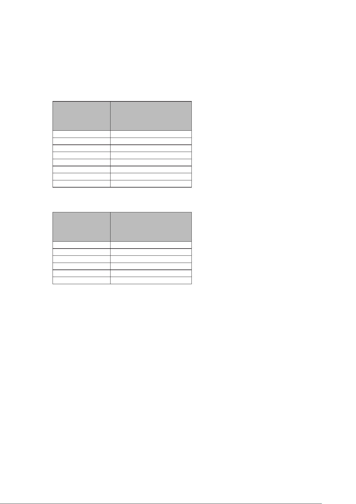
● 対応解像度
この製品は次の解像度に対応しています。
The monitor supports the following resolutions.
本显示器支持下列分辨率。
모니터에서 지원하는 해상도는 다음과 같습니다.
/ Compatible Resolutions
兼容的分辨率
/
アナログ信号入力時/Analog Input / 模拟输入 / 아날로그 입력
호환되는 해상도
/
解像度
Resolution
分辨率
해상도
640 × 480 ~75 Hz
720 × 400 70 Hz
800 × 600 ~75 Hz
1024 × 768 ~75 Hz
1152 × 864 75 Hz
1152 × 900 ~76 Hz
1280 × 960 60 Hz
1280 × 1024
*1
垂直走査周波数
Vertical Scan Frequency
垂直扫描频率
수직 스캔 주파수
~75 Hz
デジタル信号入力時/Digital Input/数字输入 / 디지털 입력
解像度
Resolution
分辨率
해상도
640 × 480 60 Hz
720 × 400 70 Hz
800 × 600 60 Hz
1024 × 768 60 Hz
1280 × 960 60 Hz
1280 × 1024
*1
垂直走査周波数
Vertical Scan Frequency
垂直扫描频率
수직 스캔 주파수
60 Hz
VESA 規格に準拠したグラフィックスボードが必要です。
The graphics board should comply with the VESA standard.
显卡应符合 VESA 标准。
그래픽 보드는 VESA 표준을 준수합니다.
*1 推奨解像度です。
*1 Recommended resolution
*1 推荐的分辨率
*1 권장 해상도
Page 3
カラー液晶モニター
タッチパネル装着カラー液晶モニター
絵表示について
本書および本体では次の絵表示を使用しています。内容をよく理解してから本文をお読みください。
日本語
警告
注意
この表示を無視して誤った取扱いをすると、人が死亡または重傷を負う可能性がある内容を
示しています。
この表示を無視して誤った取扱いをすると、人が傷害を負う可能性がある内容、および物的
損害のみ発生する可能性がある内容を示しています。
注意(警告を含む)を促すものです。
禁止の行為を示すものです。
行為を強制したり指示するものです。
セットアップマニュアルと取扱説明書の記載内容について
セットアップマニュアル
(本書)
モニターの取扱説明書
※1
タッチパネルドライバの取
扱説明書
※1※2
使用上の注意およびモニターの設置から使いはじめるまで
の基本説明。
モニターの画面調整や設定、仕様などについての応用説
明。
タッチパネルドライバのインストール方法や使用方法につ
いての説明。
TPOsetの取扱説明書
※1 CD-ROM内、PDFファイル(PDFファイルを見るには、Adobe® Readerのインストールが必要です。)
※2 FDS1904Tの場合にのみ使用します。
1. 本書の著作権はEIZO株式会社に帰属します。本書の一部あるいは全部をEIZO株式会社からの事前の許諾
を得ることなく転載することは固くお断りします。
2. 本書の内容について、将来予告なしに変更することがあります。
3. 本書の内容については、万全を期して作成しましたが、万一誤り、記載もれなどお気づきの点がありま
したら、ご連絡ください。
4. 本機の使用を理由とする損害、逸失利益などの請求につきましては、上記にかかわらず、いかなる責任
も負いかねますので、あらかじめご了承ください。
5. 乱丁本、落丁本の場合はお取り替えいたします。販売店までご連絡ください。
※1※2
TPOset(タッチパネルの感度調整用ソフトウェア)の使
用方法についての説明。
1
Page 4
使用上の注意
重要
• この製品は、船舶の海図表示システム、レーダー表示用、または機関監視用用途などでの使用を意
図しています。
次のような極めて高い信頼性、安全性が必要とされる用途への使用は意図しておりませんので、これらの用途
には使用しないでください。
- 防災防犯装置など各種安全装置
- 生命に直接関わる装置(生命維持装置や手術室用機器などの医療用機器)
- 原子力制御機器(原子力制御システム、原子力施設の安全保護系システムなど)
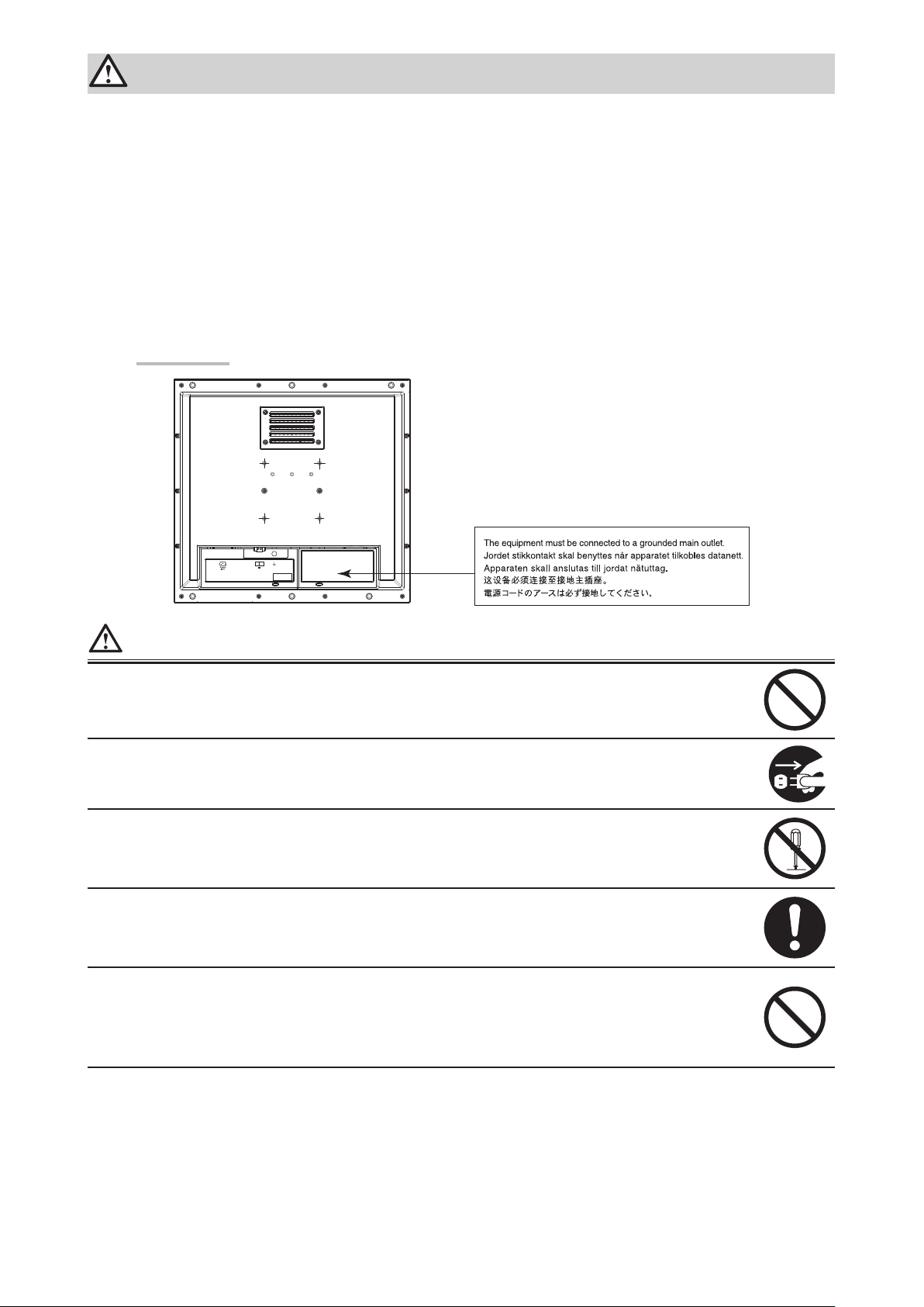
• ご使用前には、「使用上の注意」および本体の「警告表示」をよく読み、必ずお守りください。
警告表示位置
-+
24V 2.7A
警告
この製品は筐体機器組み込み型のため、モニター単体での使用は絶対にしない
そのまま使用すると感電や故障の原因となります。
万一、異常現象(煙、異音、においなど)が発生した場合は、すぐに電源を切り、電源入力を
遮断して販売店またはEIZOサポートに連絡する
そのまま使用すると火災や感電、故障の原因となります。
裏ぶたを開けない、製品を改造しない
この製品の内部には、高電圧や高温になる部分があり、感電、やけどの原因となります。ま
た、改造は火災、感電の原因となります。
修理は販売店またはEIZOサポートに依頼する
お客様による修理は火災や感電、故障の原因となりますので、絶対におやめください。
異物を入れない、液体を置かない
この製品の内部に金属、燃えやすい物や液体が入ると、火災や感電、故障の原因となります。
万一、この製品の内部に液体をこぼしたり、異物を落とした場合には、すぐに電源入力を遮断
して、販売店またはEIZOサポートにご連絡ください。
2
Page 5
警告
次のような場所で使用しない
火災や感電、故障の原因となります。
・屋外。強い振動や衝撃を受ける場所への搭載。
・湿気やほこりの多い場所。
・水滴のかかる場所。浴室、水場など。
・油煙や湯気が直接当たる場所や熱器具、加湿器の近く。
・直射日光が直接製品に当たる場所。
・可燃性ガスのある環境。
使用者が背面の電源入力部に触れることがないように設置する
電源入力部に触れると感電の原因となります。
電源入力部に対しては、組み込み後の最終製品の適用規格に従って絶縁保護してください。
定格電圧範囲内で使用する
火災や感電、故障の原因となります。
電源: AC AC100-240V、50/60Hz
DC DC+24V
AC電源コネクタを使用する場合は、電源コードが次の要件を満たしていることを確認する
この製品に電源コードは付属していません。要件を満たす電源コードを準備してください。
日本語
* 電源コードは、この製品を使用する国や地域の強制規格に適合したものでなければなりま
せん。
- 日本: 定格 AC125V 7A 、 コードタイプ VCTF、0.75mm
- ヨーロッパ: 定格 AC250V 10A、 コードタイプ H05VV-F、GTCE-3、0.75mm
- アメリカ: 定格 AC125V 10A、 コードタイプ SVT、3/18AWG(0.75mm2)
- 中国: 定格 AC250V 10A、 コードタイプ 配60227 IEC53 3×1平方毫米
2
2
AC電源コネクタを使用する場合は、電源コードのアースを必ず接地する
感電の原因となります。
DC電源端子台を使用する場合は、確実に接続する
端子台が外れると火災や感電の原因となります。
次のような誤った電源接続をしない
誤った接続は火災、感電、故障の原因となります。
・本体表示や取扱説明書で指定された極性、電源電圧以外への接続。
・タコ足配線。
すべての電源接続が完了してから、電源を入力する
電源が入力された状態で接続すると、感電の原因となります。
DC電源端子台を使用している場合は、通電中に端子台に触れない
端子台に触れると感電の原因となります。
電源コードを抜くときは、プラグ部分を持つ
コード部分を引っ張るとコードが傷つき、火災、感電の原因となります。
3
Page 6
警告
DC電源端子台を取り外すときは、端子台部分を持つ
ケーブル部分を引っ張るとケーブルが傷つき、火災、感電の原因となります。
電源コードを傷つけない
電源コードに重いものをのせる、引っ張る、束ねて結ぶなどをしないでください。電源コード
が破損(芯線の露出、断線など)し、火災や感電の原因となります。
液晶パネルが破損した場合、破損部分に直接素手で触れない
もし触れてしまった場合には、手をよく洗ってください。
万一、漏れ出た液晶が、誤って口や目に入った場合には、すぐに口や目をよく洗い、医師の診
断を受けてください。そのまま放置した場合、中毒を起こす恐れがあります。
注意
運搬のときは、接続コードやオプション品を外す
コードを引っ掛けたり、移動中にオプション品が外れたりして、けがの原因となります。
通風孔をふさがない
・通風孔の上や周囲にものを置かない。
・風通しの悪い、狭いところに置かない。
・横倒しや逆さにして使わない。
通風孔をふさぐと、内部が高温になり、火災や感電、故障の原因となります。
濡れた手で電源プラグに触れない
感電の原因となります。
電源プラグ周辺は定期的に掃除する
ほこり、水、油などが付着すると火災の原因となります。
クリーニングの際は電源入力を遮断する
電源を入力したままでおこなうと、感電の原因となります。
4
Page 7
梱包品の確認
次のものがすべて入っているか確認してください。万一、不足しているものや破損しているものがある場合は、販
売店またはEIZOサポートにご連絡ください。
参考
• 梱包箱や梱包材は、この製品の移動や輸送用に保管していただくことをお勧めします。
• モニター本体
• EIZO LCDユーティリティディスク(CD-ROM)
• セットアップマニュアル(保証書付き(本書))
• お客様ご相談窓口のご案内
• クリーニングクロス
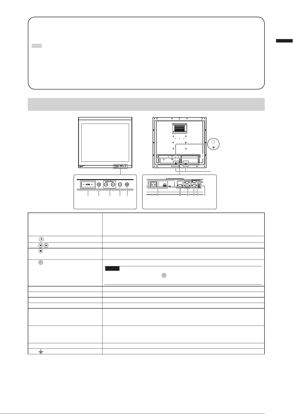
各部の名称と機能
日本語
-+
24V 2.7A
13
12
1 2 4 5 7 9 106 8
1. ECDISインジケータ モニターの輝度がECDISの調整値に設定されている場合は、「ECDIS」の文字が
2.
(RETURN)ボタン
(BRILLIANCE)ボタン
3.
(ENTER/MENU)ボタン※1調整メニューを表示し、各メニューの調整項目を決定したり、調整結果を保存
4.
5.
6. 電源入力 左:AC電源コネクタ/右:DC電源端子台
7. 信号出力コネクタ D-Sub15ピン(ミニ)コネクタ
8. 信号入力コネクタ 上:D-Sub15ピン(ミニ)コネクタ/下:DVI-Dコネクタ
9. RS-232Cポート D-Sub9ピン(メス)コネクタ:モニター制御用
10. RS-232Cポート
(FDS1904Tのみ)
11. USBポート
(FDS1904Tのみ)
12. ケーブルホルダー(2箇所) ケーブル抜け防止のため、ケーブルを固定します。
13.
※1 電源を入れると、ボタンが橙色に点灯します。
※2 同時に使用することはできません。両方にケーブルを接続すると、USB接続が優先されます。
※1
ボタン
マーク 機能接地端子
※1
※2
※2
3
緑色に点灯します。
輝度がECDISの調整値より高い場合は「+」が、低い場合は「-」が赤色に点灯
します。
調整/設定をキャンセルしたり、調整メニューを終了します。
※1
画面の明るさを調整します。
します。
電源のオン/オフを切り替えます。
注意点
• 電源をオフにするときは、 を5秒以上押してください。
(電源オフの予告メッセージが表示されます。)
D-Sub9ピン(オス)コネクタ:タッチパネル制御用
タッチパネルモニターとして使用する場合に、コンピュータとモニターをRS232Cケーブルで接続します。
アップストリームポート:タッチパネル制御用
タッチパネルモニターとして使用する場合に、コンピュータとモニターをUSB
ケーブルで接続します。
11
5
Page 8
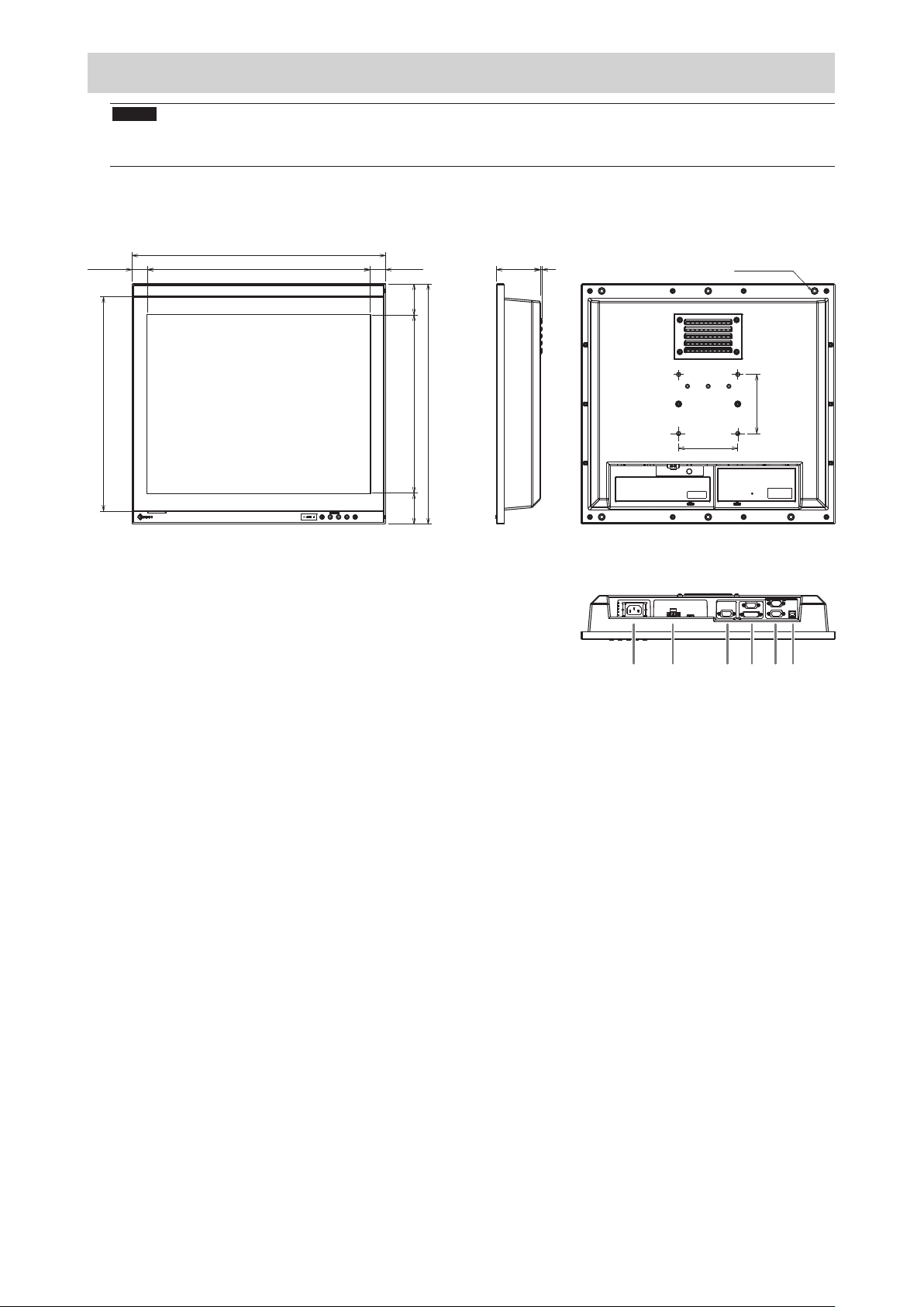
設置する
429
362
1 2 3 4 5
6
注意点
• 周囲に十分な空間を確保し、空気が循環するように設置してください。
• 設置場所を変更した場合は、キャリブレーションを実行してください(FDS1904Tのみ)。
● 外観図
26.34
376.32
26.34
52.47
74.5
4
単位:mm
筐体取付穴
(上下3箇所)
呼び径5
画面表示領域
406
301.06
100
52.47
1. AC電源コネクタ
2. DC電源端子台
3. D-Sub 15ピン(ミニ)コネクタ(出力)
4. 上:D-Sub15ピン(ミニ)コネクタ(入力)
下:DVI-Dコネクタ
5. 上:D-Sub9ピンコネクタ(タッチパネル制御用:FDS1904Tのみ)
下:D-Sub9ピンコネクタ(モニター制御用)
6. USBポート(タッチパネル制御用:FDS1904Tのみ)
100
6
Page 9
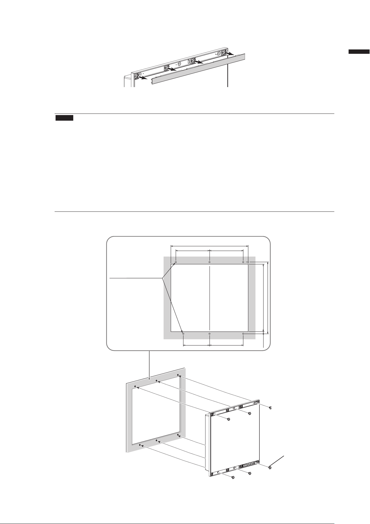
● 取付方法
モニター本体にはめ込まれているねじ目隠しカバーを取り外します。
1.
ねじ目隠しカバー(上/下)
モニターの筐体取付穴(上下3箇所)と組み込み先の筐体をねじで固定します(推
2.
奨トルク:1.6~1.8N・m)。
注意点
• この製品に取り付け用のねじは付属していません。別途、組み込み先の筐体に対応する、呼び径5mmのねじ
(6本)を準備してください。
• この製品の設置可能な角度(チルト)は次のとおりです。
- 0°(垂直)~60°上向き
• モニターはコンパスから離して設置してください。コンパスの誤差の原因となります。
モニターとコンパスとの安全距離は次のとおりです。
- 標準コンパス:0.95m
- 操舵用コンパス:0.60m
• 縦置きに設置する場合は、時計回りに90˚回転してください。
• アームや金具などを使用する場合は、VESA準拠のものを選択してください。また、取り付けには、M4×
12mmのねじをご使用ください。
日本語
●
取付条件
• パネル開口寸法/ねじ穴間隔(単位:mm)
取付穴
(上下3箇所)
呼び径5
180
140
412
180
180
382
360
11±0.3
モニター下部には通風孔があります。十分な空
間を確保するため、組み込み先の筐体の厚みは
7mm以下にしてください。
ねじ
(呼び径5mm)
7
Page 10

ねじ目隠しカバーをモニターに取り付けます。
3.
モニター本体にはめ込んでください。
8
Page 11
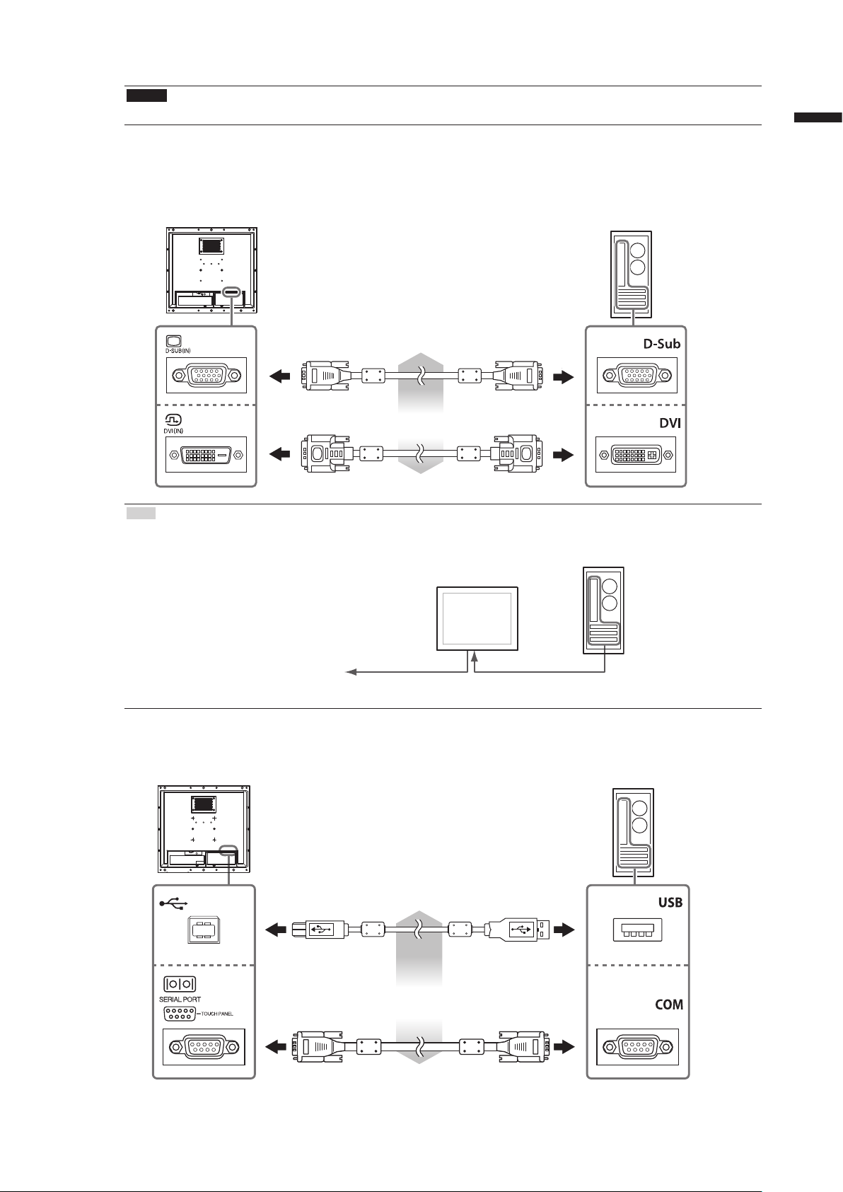
● 接続方法
注意点
• 使用するコネクタにキャップが取り付けてある場合は、ケーブル接続時に取り外してください。
信号ケーブルを信号入力コネクタとコンピュータに接続します。
1.
コンピュータのコネクタの形状を確認して、ケーブルを接続してください。
接続後、各コネクタの固定ねじを最後までしっかりと回して、確実に固定してください。
日本語
アナログ接続
(D-Sub)の場合
デジタル接続
(DVI)の場合
参考
• モニターに入力された信号を他のモニターに出力することができます(アナログ信号のみ)。信号ケーブル
をモニターの信号出力コネクタと他のモニターに接続してください。
他のモニターへ
※モニターの電源が入っていないと、信号を出力することはできません。
FDS1904Tを使用する場合は、USBケーブルまたはRS-232Cケーブル(クロスタイ
2.
または
V55(オプション)
DD200(オプション)
D-SUB(IN)D-SUB(OUT)
プ)をモニターとコンピュータに接続します。
USBケーブル(市販品)
または
RS-232Cケーブル(市販品)
9
Page 12
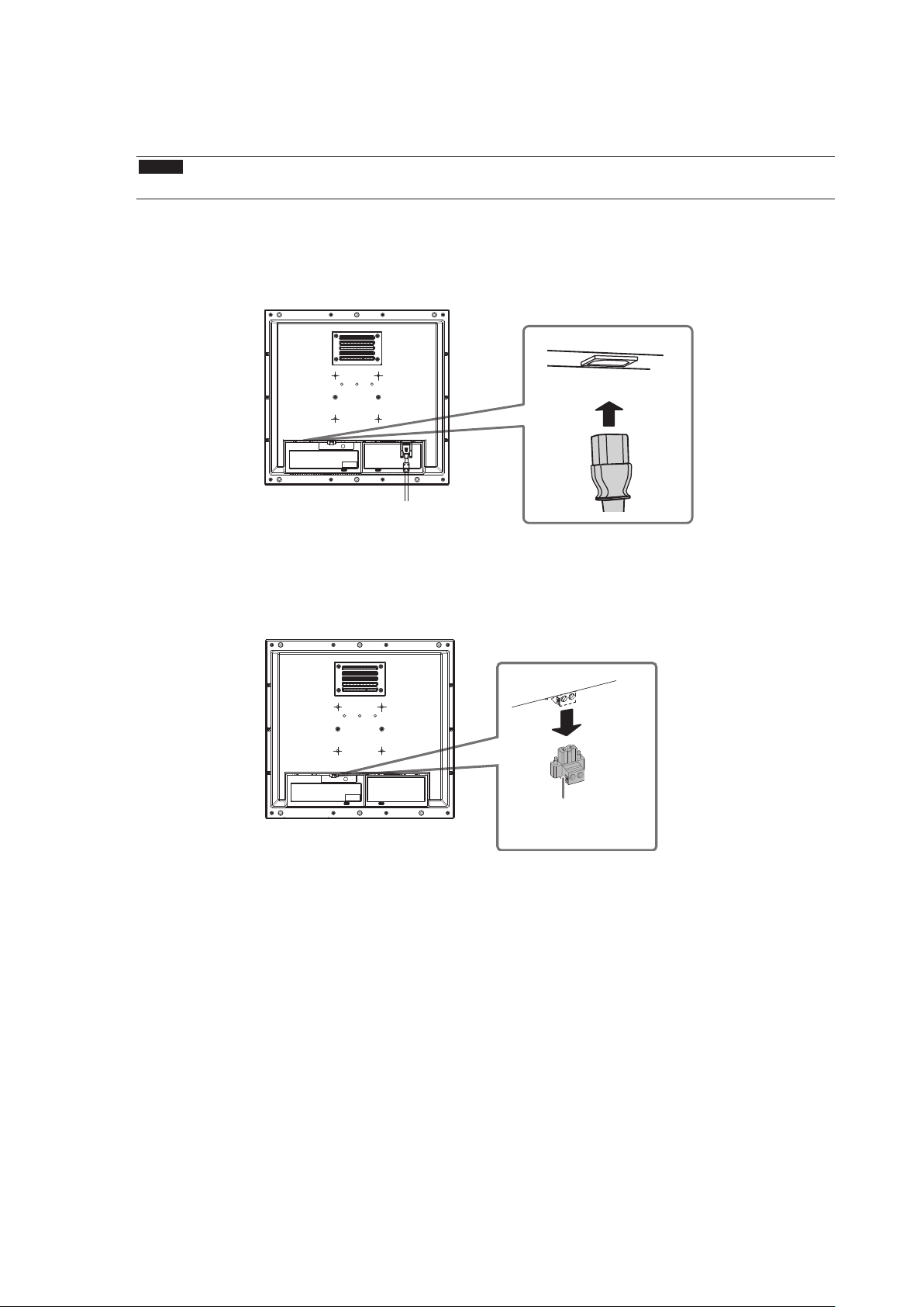
モニターを電源に接続します。
3.
電源への接続方法は次の2とおりあります。設置環境や使用条件などに応じて接続してください。
• AC電源コネクタを使用する場合
• DC電源端子台を使用する場合
注意点
• 電源への接続が完了するまで、モニターの電源を入力したり、接続する電線に通電したりしないでください。
●
AC電源コネクタを使用する場合
1. AC電源コネクタに電源コードを接続します。
電源プラグを確実に固定してください。
2. 電源コンセントに電源コードを接続します。
●
DC電源端子台を使用する場合
1. 端子台を取り外します。
DC電源端子台
10
Page 13
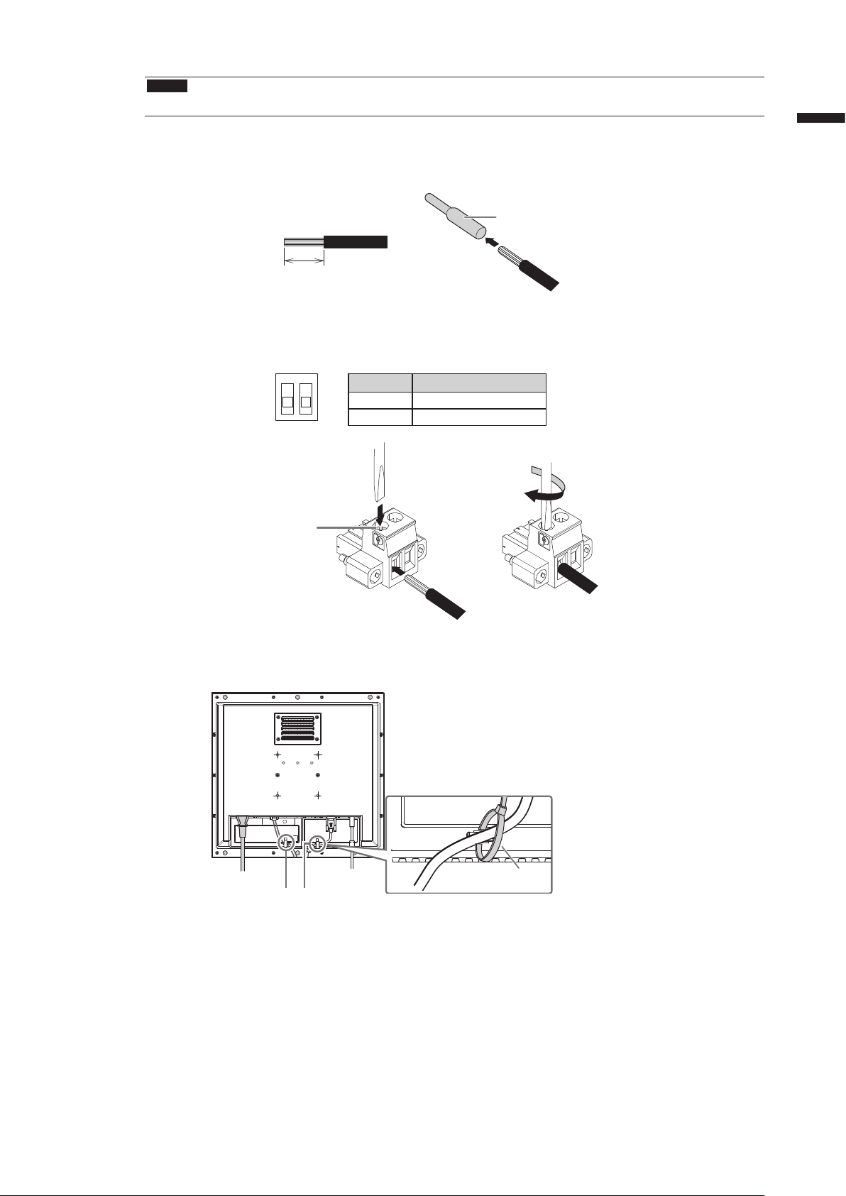
2. 端子台に電線を接続します。
注意点
• 電線は、AWG 18~12(0.8~3mm2)のものを使用してください。
1. 電線の被覆を剥きます(被覆剥き線長さ:7±0.5mm)。
2. 先端処理が必要な場合は、棒端子(フェルール)を取り付けます。
フェルールは、フエニックス・コンタクト社製のものをご使用ください。
棒端子
7±0.5mm
3. 端子台に電線を挿入し、先端幅2.5mmのマイナスドライバでクランプねじを締めます(推奨トルク:0.5
~0.6N・m)。
端子台の入力極性は次のとおりです。
ピンNo. 入力極性
1 2
マイナスドライバ
1 DC+
2 DC-
日本語
クランプねじ
電線
ケーブル類が抜けないようクランパーで固定します。
4.
クランパー
(DC電源端子台)
信号ケーブル用電線用
※1 この製品にクランパーは付属していません。
別途準備してください。
※1
11
Page 14
画面を表示する
を押して、モニターの電源を入れます。
1.
モニターの操作ボタンが橙色に点灯します。
コンピュータの電源を入れます。
2.
画面が表示されます。
電源を入れても画面が表示されない場合には、「症状に対する処置をおこなっても解消されない場合
は、販売店またはEIZOサポートにご相談ください。」(P.13)を参照してください。
FDS1904Tを使用する場合は、引き続きタッチパネルの設定をおこなってください。
注意点
• 使用後は、電源を切ってください。
タッチパネルの設定をする(FDS1904T)
● モニターとコンピュータをUSBケーブルで接続している場合
OSがWindows8.1/Windows8/Windows7のとき
Windows標準のタッチパネルドライバを使用します。新たにドライバをインストールする必要はあ
りません。
キャリブレーションなど、タッチパネルの設定をおこなってください。詳細は、モニターの取扱説明
書(CD-ROM 内)を参照してください。
OSがWindowsXPのとき
「EIZO LCD ユーティリティディスク」(CD-ROM)のタッチパネルドライバを使用します。ドライ
バのインストール方法、設定方法などについては、タッチパネルドライバの取扱説明書(CD-ROM
内)を参照してください。
● モニターとコンピュータをRS-232Cケーブルで接続している場合
「EIZO LCD ユーティリティディスク」(CD-ROM)のタッチパネルドライバを使用します。ドライ
バのインストール方法、設定方法などについては、タッチパネルドライバの取扱説明書(CD-ROM
内)を参照してください。
注意点
• 「EIZO LCD ユーティリティディスク」(CD-ROM)のタッチパネルドライバを使用する場合は、ドライバをイン
ストールする前に、USBケーブルまたはRS-232Cケーブルがモニターとコンピュータに接続されていることを確認
してください。
• OSがWindows XPの場合は、「タッチパネル設定ツール」の「基本設定」で、「設定ファイル」を「Mouse.mfd」
に変更してください。「Touch.mfd」(初期設定)にすると、タッチ位置が正しく認識されないことがあります。
12
Page 15
こんなときは
症状に対する処置をおこなっても解消されない場合は、販売店またはEIZOサポートにご相談ください。
● 画面が表示されない場合
症状 原因と対処方法
1. 画面が表示されない
• すべての操作ボタンが点灯しない
•
ボタンのみ点灯:橙色 • を押してください。
• すべての操作ボタンが点灯:橙色 • 画面の明るさを調整してみてください。
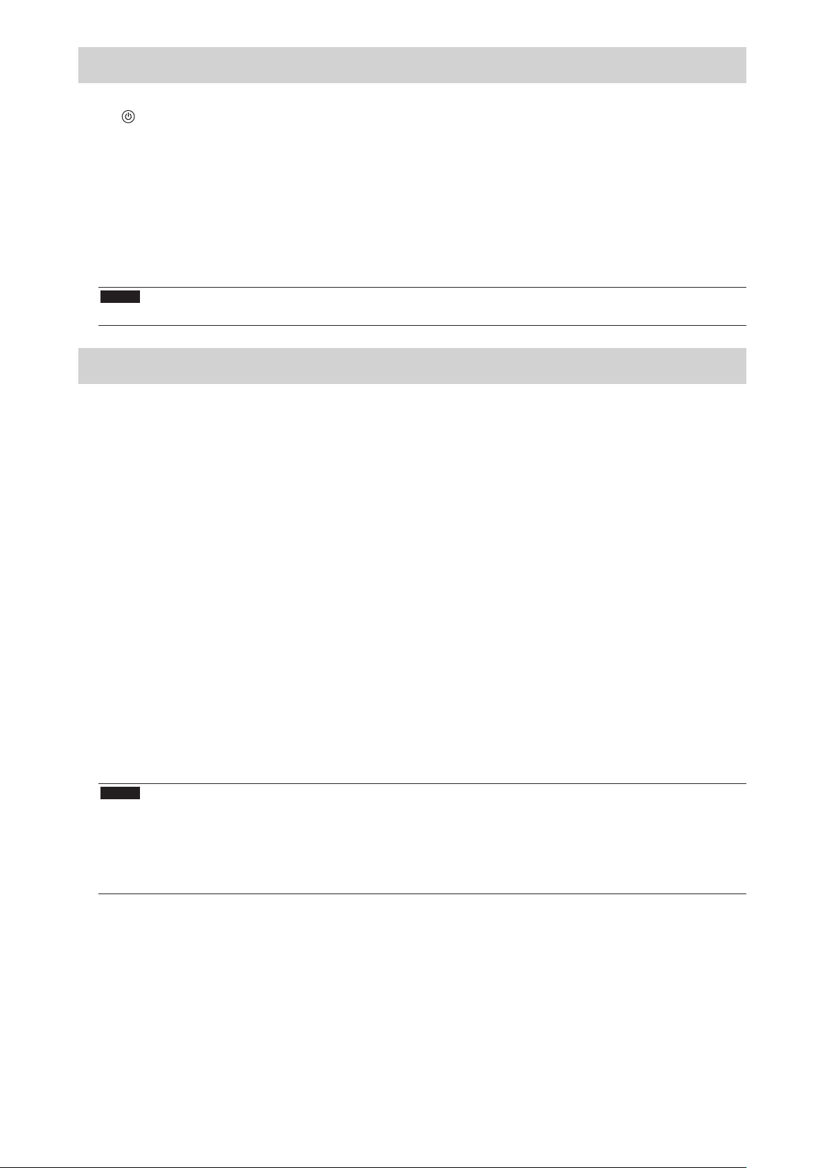
2. 次のようなメッセージが表示される この表示はモニターが正常に機能していても、信号が正
• 信号が入力されていない場合の表示です。
例:
• 電源コードは正しく接続されていますか。
• 主電源を入れてください。
• 主電源を切り、数分後にもう一度電源を入れてみてく
ださい。
• マウス、キーボードを操作してみてください。
• コンピュータの電源は入っていますか。
しく入力されないときに表示されます。
• コンピュータによっては電源を入れても信号がすぐに
出力されないため、左のような画面が表示されること
があります。
• コンピュータの電源は入っていますか。
• 信号ケーブルは正しく接続されていますか。
日本語
• 入力されている信号が周波数仕様範囲外であ
ることを示す表示です。(範囲外の周波数は
マゼンタで表示されます。)
例:
fD: ドットクロック(デジタル信号入力時の
み表示されます)
fH: 水平走査周波数
fV: 垂直走査周波数
• コンピュータの設定が、この製品で表示できる解像
度、垂直走査周波数になっていますか(「対応解像
度」(表紙の裏)参照)。
• コンピュータを再起動してみてください。
• グラフィックスボードのユーティリティなどで、適切
な表示モードに変更してください。詳細はグラフィッ
クスボードの取扱説明書を参照してください。
13
Page 16
● 画面に関する症状(デジタル・アナログ共通)
症状 原因と対処方法
1. 画面が明るすぎる/暗すぎる • 調整メニューの「ブリリアンス」を調整してください
(モニターの取扱説明書(CD-ROM内)参照)。(液晶
モニターのバックライトには、寿命があります。画面が
暗くなったり、ちらついたりするようになったら、EIZO
サポートにご相談ください。)
2. 画面が突然暗くなった/調整メニューの
「ブリリアンス」の値を上げることができ
ない
3. 文字がぼやけて見える • コンピュータの設定が、この製品で表示できる解像度、
4. 残像が現れる • この現象は液晶パネルの特性であり、固定画面で長時間
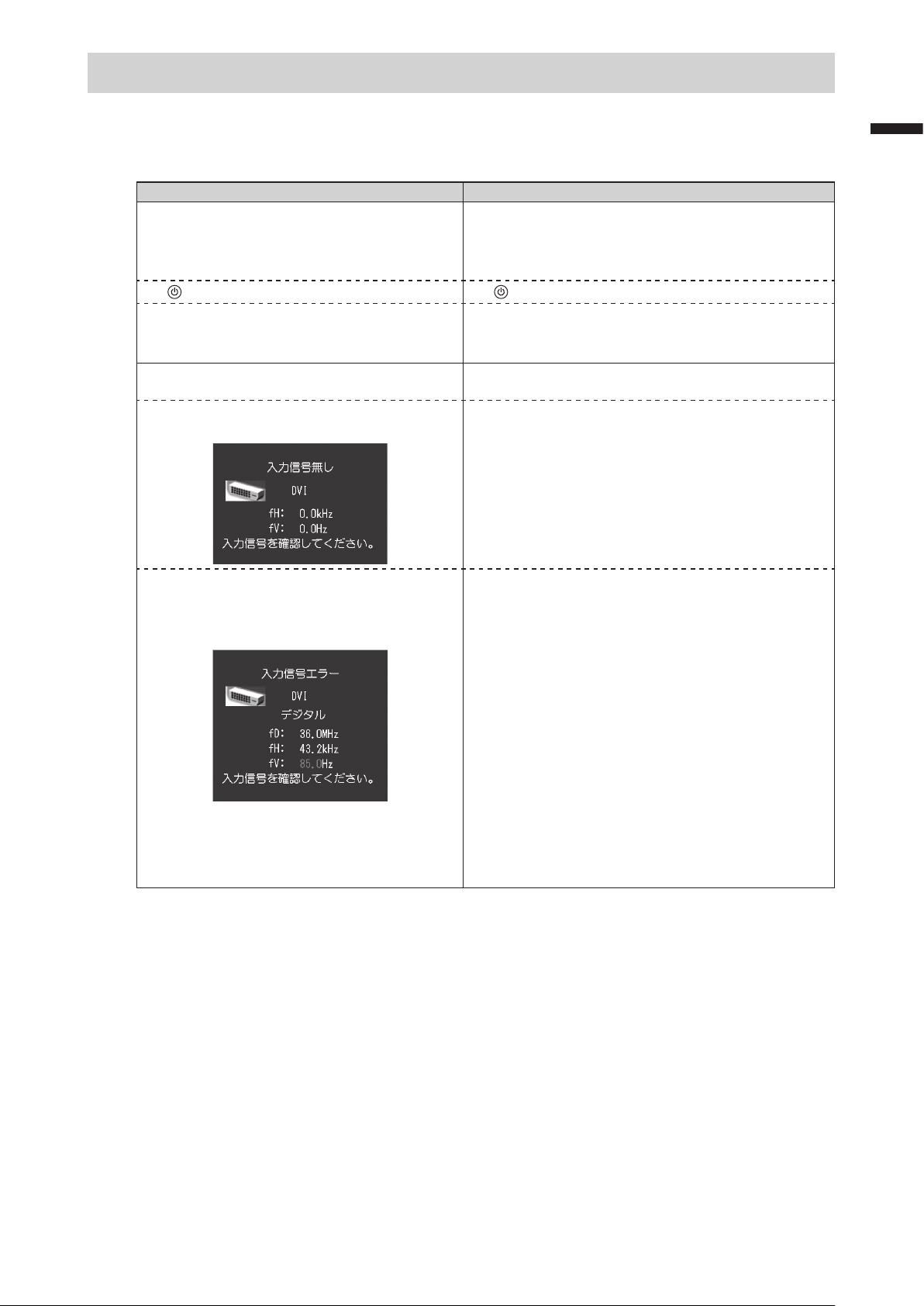
5. 画面に緑、赤、青、白のドットが残るまた
は点灯しないドットが残る
6. 画面上に干渉縞が見られる/パネルを押し
た跡が消えない
7. 画面にノイズが現れる • HDCP方式の信号を入力した場合、正常な画面がすぐに表
8. 画面を拭いても曇りが取れない/ガラスの
内側に結露が生じた
• この製品は常に本体内部の温度を監視しています。内部
が高温になり、一定の温度を超えると、温度を下げるた
め自動的に次の状態になります。
-「ブリリアンス」の設定値が下がる
-「ブリリアンス」の設定値を上げることができない
この状態は、内部の温度が下がると元に戻ります。
また、「ブリリアンス」を下げても、本体内部の温度が
さらに高くなった場合には、「WARNING」のメッセー
ジが表示され、自動的にモニターの電源が切れます。
(電源ランプが緑色に点滅します。)
垂直走査周波数になっていますか(「対応解像度」(表
紙の裏)参照)。
• 調整メニューの「輪郭補正」で調整してみてください
(モニターの取扱説明書(CD-ROM内)参照)。
使用することをできるだけ避けることをお勧めします。
• 長時間同じ画像を表示する場合は、コンピュータのスク
リーンセーバーまたはパワーセーブ機能を使用してくだ
さい。
• これらのドットが残るのは液晶パネルの特性であり、故
障ではありません。
• 画面全体に白い画像または黒い画像を表示してみてくだ
さい。症状が解消されることがあります。
示されないことがあります。
• 画面を拭いても曇りが取れない場合は、パネルを保護し
ているガラスの内側に結露が生じていることがありま
す。この場合は、モニターの電源を入れて画面を表示し
てください。しばらくすると結露は消えます。また、ド
ライヤーなどでガラスを温めることで結露が消えるまで
の時間が短くなる場合があります。なお、このようにガ
ラスの内側に結露が発生しても、製品の故障や劣化には
影響はありません。
● 画面に関する症状(アナログのみ)
症状 原因と対処方法
1. 画像がずれている • 調整メニューの「ポジション」で画像の位置を合わせ
2. 画面に縦線が出ている/画面の一部がちらつい
ている
14
てください(モニターの取扱説明書(CD-ROM内)参
照)。
• グラフィックスボードのユーティリティなどに画像の
位置を変える機能があれば、その機能を使用して調整
してください。
• 調整メニューの「クロック」で調整してみてください
(モニターの取扱説明書(CD-ROM内)参照)。
Page 17
症状 原因と対処方法
3. 画面全体がちらつく、にじむように見える • 調整メニューの「フェーズ」で調整してみてください
(モニターの取扱説明書(CD-ROM内)参照)。
● その他の症状
症状 原因と対処方法
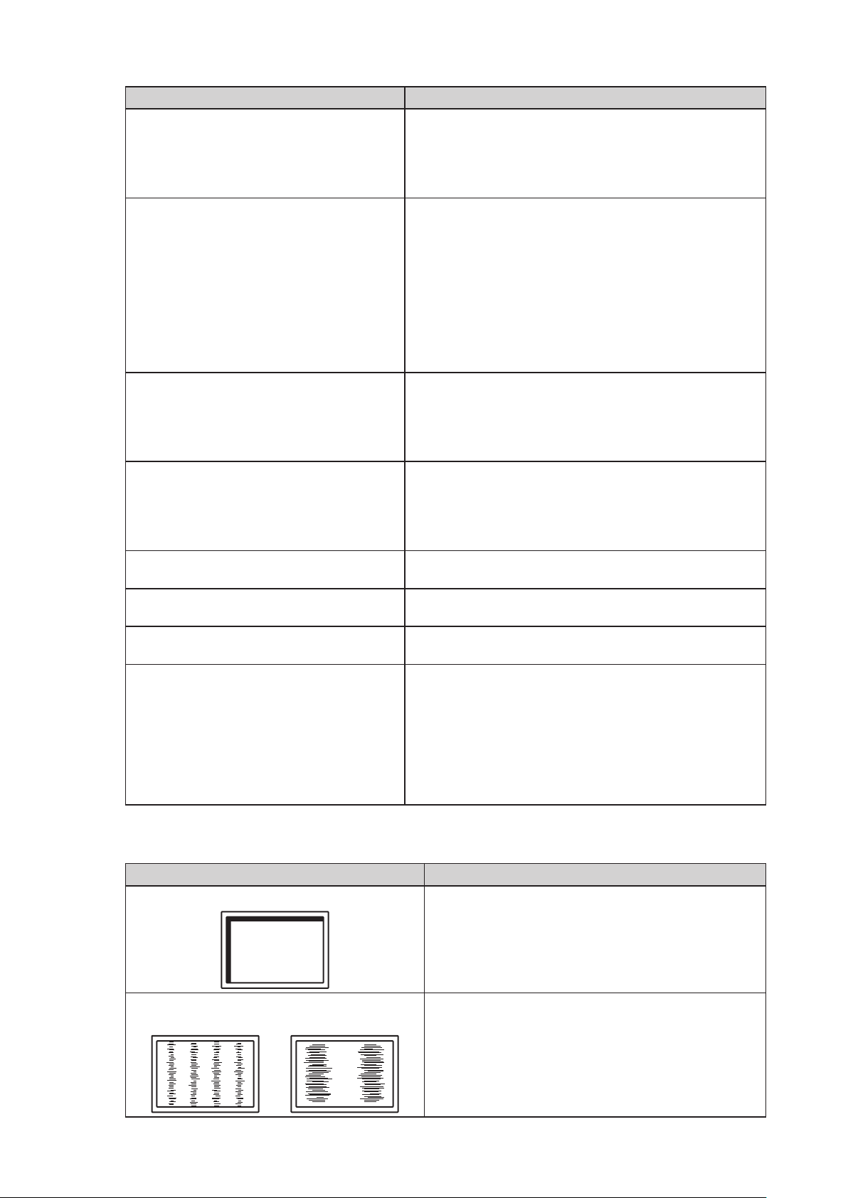
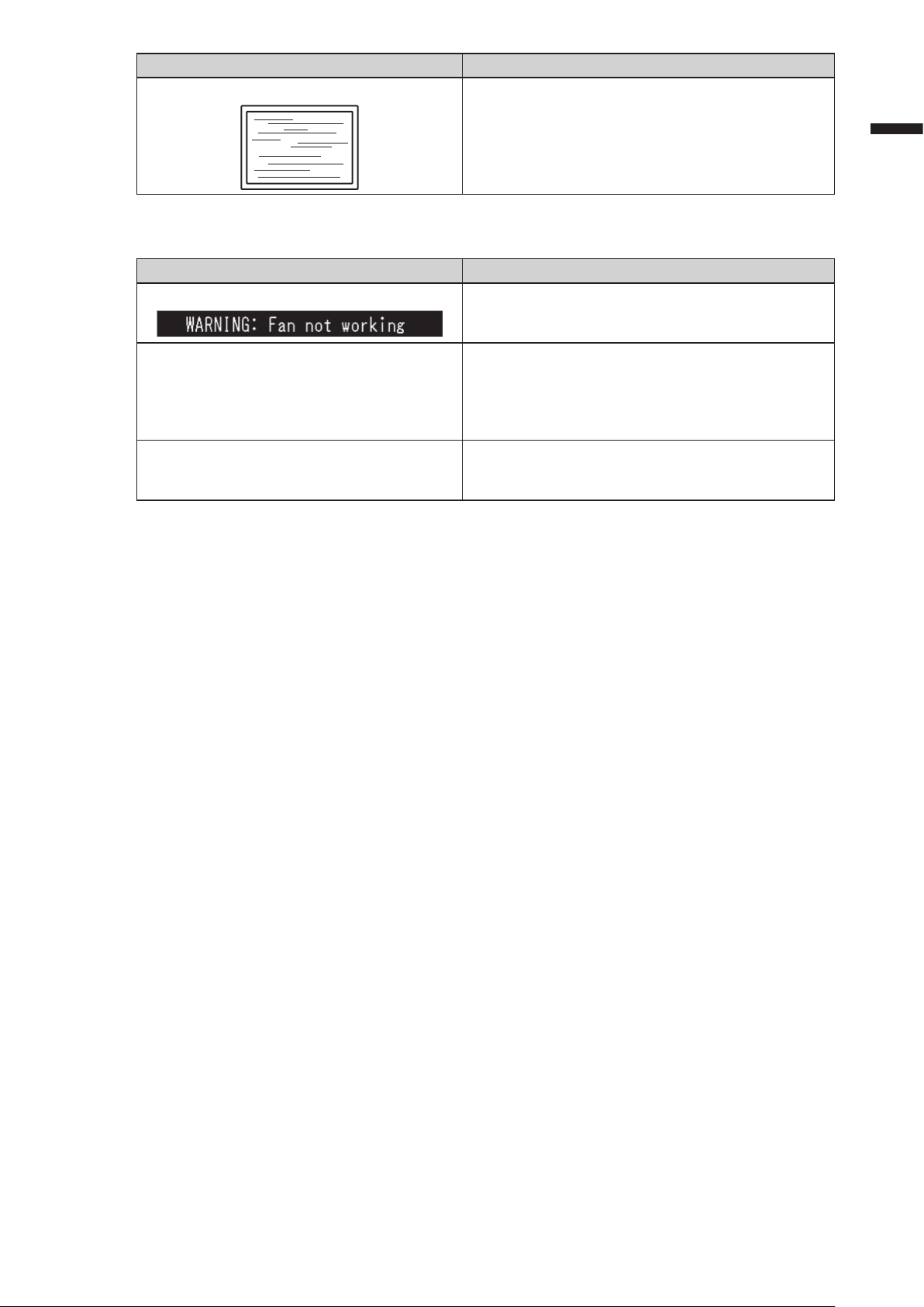
1. 画面に次のようなメッセージが表示される • 本体の冷却ファンが正常に動作していないときに表示
されます。本体背面の冷却ファンの状態を確認してく
ださい。
2. 調整メニューが表示できない • 操作ボタンのロックが機能していないか確認してみ
てください(モニターの取扱説明書(CD-ROM内)参
照)。
• ロックが機能していると、画面に「Locked」と表示
されます。
3. ファンの動作音が気になる • この製品は、本体内部の温度上昇を抑えるための冷却
ファンを内蔵しています。設置位置によっては動作音
が聞こえる場合がありますが、異常ではありません。
日本語
15
Page 18
● タッチパネルに関する症状(FDS1904T)
症状 原因と対処方法
1. タッチ操作が効かない • モニターとコンピュータがUSBケーブルまたは
RS-232Cケーブルで接続されていることを確認してく
ださい。
• モニターの電源を入れなおしてみてください。
• モニターおよびコンピュータの電源コードのアース
が接地されていることを確認してください。アース
が接地されていないと、誤動作の原因となることが
あります。
• TPOsetでタッチパネルの感度調整を実行してみてく
ださい。
2. タッチ位置とカーソル位置がずれる/カーソル
が飛ぶ
3. カーソルがタッチ位置に表示されず、モニター
の中央を中心に点対称の位置に表示される
4. カーソルが揺れる/描画線が安定しない • モニターおよびコンピュータの電源コードのアース
5. (ご使用のOSがWindows8.1/Windows8/
Windows7の場合)
キャリブレーションが正しく動作しない
• セットアップマニュアルに記載のケーブルでモニ
ターとコンピュータを接続してください。変換アダ
プタなどを利用すると、タッチパネルが正しく動作
しない場合があります。
• モニターの電源を入れなおしてみてください。
• 再度キャリブレーションを実行してください。
• モニターおよびコンピュータの電源コードのアース
が接地されていることを確認してください。アース
が接地されていないと、誤動作の原因となることが
あります。
• TPOsetでタッチパネルの感度調整を実行してみてく
ださい。
• モニターの位置や角度を変更すると、カーソルが飛
ぶ場合があります。
• 金属をパネル面に近づけた状態で使用するとカーソ
ル位置がずれる場合があります。
• タッチパネルが汚れていると、誤動作する場合があ
ります。モニターの取扱説明書(CD-ROM内)を参
照し、パネル面のクリーニングをおこなってくださ
い。
• パネル面のクリーニングに帯電防止剤入りのクリー
ナを使用するとタッチパネルの感度に影響し、カー
ソル位置がずれる原因になることがあります。
• コンピュータやモニターの起動時、およびケーブル
の接続後、5秒間はタッチしないでください。カーソ
ル位置がずれたり、タッチ操作が効かなくなる場合
があります。その場合は、およそ2分間タッチパネル
に触れずにおくか、モニターの電源を入れなおして
ください。それでも改善しないときは、再度キャリ
ブレーションを実行してください。
• 再度キャリブレーションを実行してください。
が接地されていることを確認してください。アース
が接地されていないと、誤動作の原因となることが
あります。
• TPOsetでタッチパネルの感度調整を実行してみてく
ださい。
• 金属の影響がある場合、カーソルが安定しない場合
があります。
• 複数台のモニターを近接して設置している場合は、
モニター間の間隔をあけて設置してください。
• いったん調整状態をリセット(Windowsコントロー
ルパネルの「タブレットPC設定」/「Tablet PC設定」
の「画面」タブで「リセット」をクリック)して、
再度キャリブレーションを実行してください。
16
Page 19
症状 原因と対処方法
6. (ご使用のOSがWindows8.1/Windows8/
Windows7の場合)
タッチ音が鳴らない
注意点
• TPOset(タッチパネルの感度調整用ソフトウェア)については、TPOsetの取扱説明書(CD-ROM内)を参
照してください。
• コンピュータの音声出力端子からのみ音が出力され
ます。タッチ音を鳴らす場合はスピーカーを接続し
てください。
• 操作の対象となるものが何もない場所をタッチして
も音は鳴りません。
日本語
17
Page 20

アフターサービス
この製品のサポートに関してご不明な場合は、EIZOサポートにお問い合わせください。EIZOサポート一覧
は、別紙の「お客様ご相談窓口のご案内」に記載してあります。
修理を依頼されるとき
• 保証期間中の場合
保証書の規定に従い、EIZOサポートにて修理または交換をさせていただきます。お買い求めの販売
店、またはEIZOサポートにご連絡ください。
• 保証期間を過ぎている場合
お買い求めの販売店、またはEIZOサポートにご相談ください。修理範囲(サービス内容)、修理費
用の目安、修理期間、修理手続きなどを説明いたします。
修理を依頼される場合にお知らせいただきたい内容
• お名前・ご連絡先の住所・電話番号/FAX番号
• お買い上げ年月日・販売店名
• 製品名・製造番号
(製造番号は、本体の背面部のラベル上に表示されている8桁の番号です。
例)S/N 12345678)
• 使用環境(コンピュータ/グラフィックスボード/OS・システムのバージョン/表示解像度など)
• 故障または異常の内容(できるだけ詳細に)
修理について
• 修理の際に当社の品質基準に達した再生部品を使用することがありますのであらかじめご了承くだ
さい。
製品回収・リサイクルシステムについて
• パソコン及びパソコン用モニターは「資源有効利用促進法」の指定再資源化製品に指定されてお
り、メーカーは自主回収及び再資源化に取り組むことが求められています。
当社製品は、一般社団法人「パソコン3R 推進協会」が回収させていただきます。
回収を希望されるお客様は当社のWeb サイトよりお申し込みください。
(http://www.eizo.co.jp)
※この製品は業務用途を意図した製品ですので、ご使用後廃棄される場合は有償となります。
ユーザー登録のお願い
お買い上げいただきましたお客様へより充実したサポートをお届けするため、次のアドレス
にアクセスし、ユーザー登録をお願いいたします。
18
http://www.eizo.co.jp/registration/
Page 21
Color LCD Monitor
Touch Panel Color LCD Monitor
SAFETY SYMBOLS
This manual and this product use the safety symbols below. They denote critical information. Please
read them carefully.
WARNING
CAUTION
Failure to abide by the information in a WARNING may result in serious injury and can be
life threatening.
Failure to abide by the information in a CAUTION may result in moderate injury and/or
property or product damage.
Indicates an attention to be required.
Indicates a prohibited action.
Indicates a mandatory action that must be followed.
About Setup Manual and User’s Manual
Setup Manual
(this manual)
Describes precautions and basic information ranging from
installation of the monitor to using the monitor.
English
User’s Manual of this
monitor
*1
User’s Manual for
Touch Panel Driver
User’s Manual for
TPOffset
*1 PDF le on the CD-ROM (Installation of Adobe Reader is required.)
*2 Used only for the FDS1904T
No part of this manual may be reproduced, stored in a retrieval system, or transmitted, in any form or by
any means, electronic, mechanical, or otherwise, without the prior written permission of EIZO Corporation.
EIZO Corporation is under no obligation to hold any submitted material or information condential unless
prior arrangements are made pursuant to EIZO Corporation’s receipt of said information. Although every
effort has been made to ensure that this manual provides up-to-date information, please note that EIZO
monitor specications are subject to change without notice.
*1*2
Describes the application information of the monitor such as
screen adjustments, settings, and specications.
Describes the installation and use of the touch panel driver.
*1*2
Describes how to use TPOffset (software for adjusting touch
panel sensitivity).
1
Page 22
PRECAUTIONS
IMPORTANT
• This product is intended for applications such as nautical chart display systems, ship radar displays,
and ship engine monitoring.
This product is not developed for applications which would require higher reliability, and safety such
as those listed below.
- Safety devices (Disaster prevention system, security control system, etc.)
- Equipment with direct effect on human life (Life support systems, Medical equipment or devices
used in the operating room, etc.)
- Nuclear energy control devices (Nuclear energy control systems, security control systems of
nuclear facilities, etc.)
• To ensure personal safety and proper maintenance, please read carefully this section and the
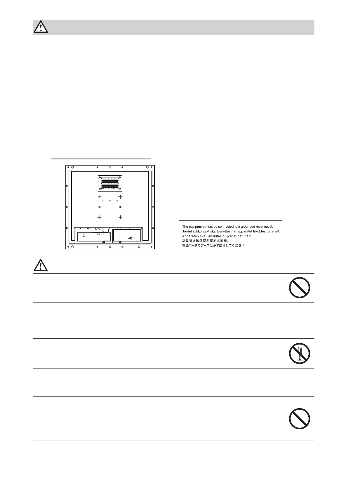
caution statements on the monitor.
Location of the Caution Statements
-+
24V 2.7A
WARNING
This product is intended to be housed in an enclosure. Do not use the bare monitor separately.
Attempting to use a malfunctioning unit may result in electric shock, or equipment damage.
If the unit begins to emit smoke, smells like something is burning, or makes strange
noises, disconnect all power connections immediately and contact your local EIZO representative for advice.
Attempting to use a malfunctioning unit may result in re, electric shock, or equipment damage.
Do not open the cabinet or modify the unit.
Opening the cabinet or modifying the unit may result in re, electric shock, or burn.
Refer all servicing to qualied service personnel.
Do not attempt to service this product yourself as opening or removing covers may result in re,
electric shock, or equipment damage.
Keep small objects or liquids away from the unit.
Small objects accidentally falling through the ventilation slots into the cabinet or spillage into
the cabinet may result in re, electric shock, or equipment damage. If an object or liquid falls/
spills into the cabinet, block the power supply immediately. Have the unit checked by a qualied
service engineer before using it again.
2
Page 23

WARNING
Use the unit in an appropriate location.
Not doing so may result in re, electric shock, or equipment damage.
• Do not place outdoors.
• Do not place in a location where it may be affected by strong vibration or shocks.
• Do not place in a dusty or humid environment.
• Do not place in a location where water is splashed on the screen (bathroom, kitchen, etc.).
• Do not place in a location where the steam comes directly on the screen.
• Do not place near heat generating devices or a humidier
• Do not place in a location where the product is subject to direct sunlight.
• Do not place in an inammable gas environment.
Install the monitor so that users are unable to touch the power input terminal on the rear
of the monitor.
Touching the power input terminal may result in electric shock.
Apply insulation protection to the power input terminal according to the applicable standards for
nished products after enclosure installation.
Use the unit within the rated voltage range.
Not doing so may result in re, electric shock, or equipment damage.
Power supply: AC AC 100-240 V, 50/60Hz
DC DC +24 V
English
If using the AC power connector, make sure the power cord meets the following requirements.
This product does not include a power cord. Please prepare separately a power cord which
meets the requirements.
* The power cord must be compliance with the mandatory standards of the country and region
in which this product is to be used.
- For Europe: The power cord set has rated value of at least AC 250V~ 10A and has cord type
H05VV-F, GTCE-3, 0.75mm
- For USA: The power cord set has rated value of at least AC 125V~ 10A and has cord type SVT,
3/18AWG (0.75mm
- For Japan The power cord set has rated value of at least AC 125V~ 7A and has cord type VCTF,
0.75mm
- For China: The power cord set has rated value of at least AC 250V~ 10A and has cord type “
60227 IEC53 3×1
2
.
2
).
平方毫米
2
.
配
”
The equipment must be connected to a grounded main outlet.
Failure to do so may result in re or electric shock.
If using the DC power terminal block, connect it securely.
Accidental disconnection of the terminal may result in re, electric shock, or equipment damage.
Use the correct voltage.
• The unit is designed for use with a specic voltage only. Connection to polarities and voltages
other than those specied on the monitor or in this User’s Manual may cause re, electric
shock, or equipment damage.
• Do not overload your power circuit, as this may result in re or electric shock.
Only supply power after completing all power connections.
Making connections with power supplied may result in electric shock.
If using the DC power terminal block, do not touch the terminal block while it is electri-
ed.
Touching the terminal block in this state may result in electric shock.
3
Page 24

WARNING
To disconnect the power cord, grasp the plug rmly and pull.
Tugging on the cord may damage and result in re or electric shock.
To remove the DC power terminal block, grasp the terminal block rmly and pull.
Tugging on the wiring may damage it and may result in re or electric shock.
Handle the power cord with care.
• Do not place the cord underneath the unit or other heavy objects.
• Do not pull on or tie the cord.
If the power cord becomes damaged, stop using it. Use of a damaged cord may result in re or
electric shock.
Do not touch a damaged LCD panel directly with bare hands.
The liquid crystal that may leak from the panel is poisonous if it enters the eyes or mouth. If any
part of the skin or body comes in direct contact with the panel, please wash thoroughly. If some
physical symptoms result, please consult your doctor.
CAUTION
Handle with care when carrying the unit.
Disconnect the power cord and cables when moving the unit. Moving the unit with the cord
attached is dangerous. It may result in injury.
Do not block the ventilation slots on the cabinet.
• Do not place any objects on the ventilation slots.
• Do not install the unit in a closed space.
• Do not use the unit laid down or upside down.
Blocking the ventilation slots prevents proper airow and may result in re, electric shock, or
equipment damage.
Do not touch the plug with wet hands.
Doing so may result in electrical shock.
Periodically clean the area around the plug.
Dust, water, or oil on the plug may result in re.
Block the power supply to the unit before cleaning it.
Cleaning the unit while the power is being supplied may result in electric shock.
4
Page 25

Package Contents
Check that all the following items are included in the packaging box. If any items are missing or damaged, contact
your local EIZO representative.
Note
• Please keep the packaging box and materials for future movement or transport of the monitor.
• Monitor
• EIZO LCD Utility Disk (CD-ROM)
• Setup Manual (this manual)
• Cleaning cloth
Controls and Functions
English
-+
24V 2.7A
13
12
1 2 4 5 7 9 106 8
3
1. ECDIS Indicator When the monitor brilliance is set to the ECDIS adjustment value, the letters “ECDIS”
light up in green. When the brilliance is higher than the ECDIS adjustment value, the “+”
will light up in red, and when it is lower the “-” will light up in red.
*1
2.
(RETURN) button
(BRILLIANCE)
3.
4.
5.
*1
button
(ENTER / MENU)
*1
button
button
*1
Cancels the setting/adjustment and exits the Adjustment menu.
Adjusts the brightness (brilliance).
Displays the Adjustment menu, determines an item on the menu screen, and saves
values adjusted.
Turns the power on or off.
Attention
• Press for 5 seconds or more to turn off the power.
(A preliminary message for powering off appears.)
6. Power input Left: AC power connector / Right: DC power terminal block
7. Output signal
D-Sub mini 15-pin connector
connector
8. Input signal connector Top: D-Sub mini 15-pin connector / Bottom: DVI-D connector
9. RS-232C port D-Sub 9-pin (female) connector: For monitor control
10. RS-232C port
(for FDS1904T only)
D-Sub 9-pin (male) connector: For touch panel control
*2
Connects a PC and monitor via a RS-232C cable when this product is used as a
touch panel monitor.
11. USB port
(for FDS1904T only)
Upstream port: For touch panel control
*2
Connects a PC and monitor via a USB cable when this product is used as a touch
panel monitor.
12. Cable holder (2) Fixes cables in place to prevent disconnection.
13.
mark Functional earth terminal
*1 These buttons light up orange when the monitor is turned on.
*2 These ports cannot be used at the same time. When cables are connected to both ports, the USB port is
prioritized.
11
5
Page 26

Installation
429
362
1 2 3 4 5
Attention
• Ensure there is sufcient space around the monitor, and install so that air can circulate.
• If its installation location has changed, please perform calibration (for FDS1904T only).
Exterior view
●
26.34
376.32
26.34
52.47
74.5
4
unit : mm
Enclosure mounting holes
(3 holes on top/bottom)
nominal diameter: 5
Display area
406
301.06
100
52.47
1. AC power connector
2. DC power terminal block
3. D-Sub mini 15-pin connector (Output)
4. TOP: D-Sub mini 15-pin connector (Input)
BOTTOM: DVI-D connector
5. TOP: D-Sub 9 -pin connector (For touch panel control: for
FDS19 04T only)
BOTTOM: D-Sub 9-pin connector (For monitor control)
6. USB port (For touch panel control: for FDS1904T only)
100
6
6
Page 27

How to assemble
●
Remove the screw covers installed on the monitor.
1.
Screw cover (top/bottom)
Fasten the screws through the enclosure mounting holes of the monitor (3
2.
holes on top/bottom) into the enclosure (recommended torque: 1.6 to 1.8 N•m).
Attention
• The mounting screws are not supplied. Prepare 5 mm nominal diameter screws (6 pcs.) separately for the
assembly enclosure.
• The installation angles (tilt) available for this product are shown below.
- 0° (upright) to 60° upward tilt
• Install the monitor away from the compasses. Other wise, an error may occur in the compasses.
The safe distance between the monitor and compass is shown below.
- Standard compass: 0.95 m
- Steering compass: 0.60 m
• When installing vertically, please turn it 90˚clockwise.
• When using a mount or ttings, please select VESA-compliant parts. Furthermore, please use M4 x 12-mm
screws for tting.
English
Mounting conditions
●
• Panel opening dimensions / Clearance between the screw holes (unit: mm)
412
180
Mounting holes
(3 holes on top/bottom)
nominal diameter: 5
140
180
180
382
360
11±0.3
A vent is located at the bottom of
the monitor. To maintain sufficient
space,ensure that the housing it is fitted in
is of a thickness of 7 mm or less.
Screw
(5 mm nominal
diameter)
7
Page 28

Install the screw covers onto the monitor.
3.
Insert the screw covers into the top and bottom spaces on the monitor.
8
Page 29

How to connect
●
Attention
• If a cap is attached to the connector for use, remove the cap when connecting the cable.
Connect the signal cables to the input signal connectors and PC.
1.
Check the shape of the connectors, and connect the cables.
After the connection, tighten the screws of the connectors to secure the coupling.
English
Analog connection
(D -Sub)
Digital connection
(DVI)
Note
• The signal input into the monitor can be output to a different monitor (analog signals only). Connect the signal
cable to the monitor’s signal output connector and then to another monitor.
To another monitor
* Signals cannot be output if the monitor is not turned on.
If using the FDS1904T, connect a USB cable or RS-232C cable (crossover type)
2.
or
MD-C87 (option)
FD-C39 (option)
D-SUB(IN)D-SUB(OUT)
between the monitor and PC.
(Commercially available product)
USB cable
or
RS-232C cable
(Commercially available product)
9
Page 30

Connect the monitor to a power supply.
3.
There are two options for connecting the monitor to a power supply. Make the connection according
to the installation environment and conditions of use.
• Using the AC power connector
• Using the DC power terminal block
Attention
• Do not turn on the monitor or electrify connecting wires until connection to the power supply is complete.
Using the AC power connector
●
1. Connect the power cord to the AC power connector.
Securely x the power plug.
2. Connect the power cord to the power outlet.
Using the DC power terminal block
●
1. Disconnect the terminal block.
DC power
terminal block
2. Connect the electrical wires to the terminal block.
Attention
• Use electrical wire of AWG 18 to 12 (0.8 to 3 mm2).
1. Strip the insulation from the electrical wires (stripping length: 7±0.5 mm).
2. Add a ferrule to the end of each wire, if required.
Use ferrules manufactured by PHOENIX CONTACT.
10
Ferrule
7±0 .5 mm
Page 31

3. Insert the electrical wires into the terminal block and tighten the clamp screws using a athead screwdriver
with a tip width of 2.5 mm (recommended torque: 0.5 to 0.6 N•m).
The input polarities of the terminal block are shown below.
Pin No. Input Polarity
1 2
Flathead screwdriver
Clamp screw
Secure the cable with a clamper to prevent disconnection.
4.
1 DC+
2 DC-
Electrical
wire
English
For electrical wires
(DC power terminal block)
For the signal cable
Clamper
*1 Clampers are not supplied with this product.
Please prepare separately.
*1
11
Page 32

Displaying the Screen
Press to turn on the monitor.
1.
The monitor operation buttons light up orange.
Turn on the PC.
2.
The screen image appears.
If an image does not appear, refer to “No picture” (page 13) for additional advice.
If using the FDS1904T, proceed to conguration of the touch panel settings.
Attention
• Turn off the monitor and PC after using them.
Conguring the Touch Panel (FDS1904T)
When using a USB cable to connect the monitor and PC
●
Windows 8.1 / Windows 8 / Windows 7
Use the standard Windows touch panel driver. Installation of a new driver is not required.
Congure touch panel settings and perform calibration. For details, refer to the Monitor User’s Manual
(on the CD-ROM).
Windows XP
Use the touch panel driver included on the EIZO LCD Utility Disk (CD-ROM). Refer to the Touch
Panel Driver User’s Manual (on the CD-ROM) for installing and conguring the driver.
When using a RS-232C cable to connect the monitor and PC
●
Use the touch panel driver included on the EIZO LCD Utility Disk (CD-ROM). Refer to the Touch
Panel Driver User’s Manual (on the CD-ROM) for installing and conguring the driver.
Attention
• When installing the touch panel driver on the “EIZO LCD Utility Disk” (CD-ROM), check in advance that the
monitor and PC are connected with a USB or RS-232C cable.
• If the OS is Windows XP, change “Conguration File” to “Mouse.mfd” under “Basic Setting” in the “Touch Screen
Properties”. The touch position may not be correctly recognized if the conguration le is “Touch.mfd” (default
setting).
12
Page 33

Troubleshooting
If a problem still remains after applying the suggested remedies, contact your EIZO representative.
No picture
●
Problem Possible cause and remedy
1. No picture
• None of the operation buttons light up.
• Only the
• All of the operation buttons light up orange. • Adjust the brightness (brilliance) of the screen.
2. The message below appears. This message appears when the signal is not input
• This message appears when no signal is
input.
Example:
button lights up orange. • Press .
• Check whether the power cord is connected properly.
• Turn the main power switch on.
• Turn off the main power, and then turn it on again a
few minutes later.
• Operate the mouse or keyboard.
• Check whether the PC is turned on.
correctly even when the monitor functions properly.
• The message shown left may appear, because some
PCs do not output the signal soon after power-on.
• Check whether the PC is turned on.
• Check whether the signal cable is connected properly.
English
• The message shows that the input signal is
out of the specied frequency range. (Such
signal frequency is displayed in magenta.)
Example:
fD: Dot clock
(Displayed only during digital signal input)
fH: Horizontal scan frequency
fV: Vertical scan frequency
• Check whether the PC is congured to meet the
resolution and vertical scan frequency requirements
of the monitor. (“Compatible Resolutions” in the Setup
Manual.)
• Reboot the PC.
• Select an appropriate display mode using the
graphics board’s utility. Refer to the manual of the
graphics board for details.
13
Page 34

Imaging problems (for both digital and analog)
●
Problem Possible cause and remedy
1. The screen is too bright or too dark. • Use “Brilliance” in the Adjustment menu to adjust it
(refer to the User’s Manual of the monitor (on the CD
ROM)). (The LCD monitor backlight has a limited life
span. When the screen becomes dark or begins to
icker, contact your local dealer.)
2. The screen suddenly became dark. / The
“Brilliance” value in the Adjustment menu
cannot be increased.
3. Characters are blurred. • Check whether the PC is congured to meet the
4. Afterimages appear. • Afterimages are particular to LCD monitors. Avoid
5. Green/red/blue/white dots or defective
dots remain on the screen.
6. Interference patterns or pressure marks
remain on the screen.
7. Noise appears on the screen. • When entering the signals of HDCP system, the
8. Cloudiness cannot be removed even
after wiping the screen. / There is dew
condensation on the interior side of the
glass.
• The monitor always monitors its internal temperature.
If the internal monitor reaches a high temperature
and exceeds the specied value, the monitor will
automatically enter the following state to decrease the
temperature.
- The “Brilliance” setting is lowered
- The “Brilliance” setting cannot be increased
This state will return to the original when the internal
temperature decreases.
If the internal temperature increases further
even after the “Brilliance” setting is decreased, a
“WARNING” message is displayed and the monitor
power is automatically turned off. (Power indicator
ashes green.)
resolution and vertical scan frequency requirements
of the monitor. (“Compatible Resolutions” in the Setup
Manual.)
• Use “Outline Enhancer” in the Adjustment menu to
adjust it (refer to the User’s Manual of the monitor (on
the CD ROM)).
displaying the same image for a long time.
• Use the screen saver or power saving function to
avoid displaying the same image for extended periods
of time.
• This is due to LCD panel characteristics and is not a
failure.
• Leave the monitor with a white or black screen. The
symptom may disappear.
normal images may not be displayed immediately.
• When cloudiness cannot be removed even by wiping
the screen, dew condensation may have occurred on
the interior side of the glass that protects the panel. In
this case, turn on the monitor and display something
on screen. The dew condensation will disappear after
a while. Also, warming the glass using a hair dryer
may make the dew condensation disappear more
quickly. Dew condensation appearing like this on the
interior side of the glass will not lead to product failure
or degradation.
14
Page 35

Imaging problems (for analog only)
●
Problem Possible cause and remedy
1. Display position is incorrect.
• Use “Position” in the Adjustment menu to correct
• If the problem persists, use the graphics board’s utility
the image position (refer to the User’s Manual of the
monitor (on the CD ROM)).
if available to change the display position.
2. Vertical bars appear on the screen or a
part of the image is ickering.
3. Whole screen is ickering or blurring.
Other problems
●
Problem Possible cause and remedy
1. The message below appears on screen.
2. The Adjustment menu does not appear. • Check whether the operation lock function works
3. The fan is noisy. • This product is tted with a cooling fan to keep the
• Use “Clock” in the Adjustment menu to adjust it (refer
to the User’s Manual of the monitor (on the CD ROM)).
• Use “Phase” in the Adjustment menu to adjust it (refer
to the User’s Manual of the monitor (on the CD ROM)).
• This message appears when the monitor’s cooling
fan is not operating correctly. Check the state of the
cooling fan on the rear of the monitor.
(refer to the User’s Manual of the monitor (on the CD
ROM)).
• If the function is active, “Locked” is displayed on the
screen.
internal temperature from rising. Depending on the
monitor’s location the fan may be audible when
operating, but this is not a defect.
English
15
Page 36

Touch panel problems (for FDS1904T only)
●
Problem Possible cause and remedy
1. Touch operation is disabled. • Check that the monitor and PC are connected with a
USB or RS-232C cable.
• Turn off and on the monitor.
• Check that the power cord of the monitor and PC
is connected to a grounded main outlet. Failure to
ground the equipment may result in malfunction.
• Perform touch panel sensitivity adjustment using
TPOffset.
2. Cursor position is not correct. / Cursor
jumps.
3. The cursor does not appear at the touched
position and instead is displayed at a
point-symmetric position with respect to
the center of the screen.
4. Cursor is jittery. / Drawing lines are not
straight and smooth.
5. (If the OS being used is Windows 8.1 /
Windows 8 / Windows 7)
Calibration does not work correctly.
6. (If the OS being used is Windows 8.1 /
Windows 8 / Windows 7)
No touch-sound.
• Connect the monitor to the PC with the cable
indicated in the Setup Manual. The touch panel may
not work correctly if a conversion adapter is used.
• Turn off and on the monitor.
• Calibrate the screen again.
• Check that the power cord of the monitor and PC
is connected to a grounded main outlet. Failure to
ground the equipment may result in malfunction.
• Perform touch panel sensitivity adjustment using
TPOffset.
• Changing the position or angle of the monitor may
cause the cursor to jump.
• Keep metals away from the panel surface.
• If the touch panel is dirty, the touch panel may not
operate properly. Refer to the User’s Manual of the
monitor (on the CD ROM) to clean the touch panel.
• The spray for preventing static electricity may
inuences the sensitivity of the touch panel.
• Do not touch the touch panel for 5 seconds after the
PC starts up, after turning on the monitor, or after
connecting the cable. Touching the touch panel
too soon may cause incorrect cursor positioning or
disable touch operation. If this occurs, either leave the
touch panel untouched for approximately 2 minutes
or turn the monitor off and on again. If the problem
persists, calibrate the screen again.
• Calibrate the screen again.
• Check that the power cord of the monitor and PC
is connected to a grounded main outlet. Failure to
ground the equipment may result in malfunction.
• Perform touch panel sensitivity adjustment using
TPOffset.
• The inuence of metal may cause jittery cursor.
• When multiple monitors are placed close to each
other, leave space between monitors.
• Reset the touch panel to the state before calibration
(by clicking “Reset” in the “Display” tab of the “Tablet
PC Settings” window accessible from the Windows
Control Panel) and then calibrate the touch panel
again.
• Sound is only output through the audio output terminal
of the PC. To hear touch sound, connect speakers.
• Sound is not output when touched positions are not
assigned any functions.
Attention
• For details on TPOffset (software for adjusting touch panel sensitivity), see the TPOffset User’s Manual (on the
CD- ROM).
16
Page 37

彩色液晶显示器
触摸式彩色液晶显示器
安全符号
本手册和本产品使用以下安全符号。这些符号表示重要信息。请仔细阅读这些信息。
警告
注意
若不遵守“警告”中的信息,可能会造成严重伤害或威胁到生命安全。
若不遵守“注意”中的信息,可能会造成中度伤害并/或使财产或产品受
损。
表示需要注意的事项。
表示禁止的动作。
表示必须遵照执行的命令动作。
关于设定手册与用户手册
设定手册
(本手册)
本显示器的用户手册
触摸屏驱动程序用户手册
中文
说明显示器连接到个人计算机以及使用显示器的预
防措施和基本信息。
*1
说明屏幕调整、设定和规格等应用信息。
*1 *2
触摸屏驱动程序的安装和使用说明。
TPOffset 用户手册
*1
光盘上的PDF文 件( 需 要 安 装 Adobe Reader。)
*2
仅适用于FDS1904T
未经EIZO Corporation事先书面许可,不得以任何形式或以任何方式(电子、机械或其它方式)复制
本手册的任何部分、或者将其存放到检索系统中或进行发送。EIZO Corporation没有义务为任何已
提交的材料或信息保密,除非已经依照EIZO Corporation书面接收的或口头告知的信息进行了事先
商议。尽管本公司已经尽最大努力使本手册提供最新信息,但是请注意,EIZO显示器规格仍会进行
变更,恕不另行通知。
*1*2
TPOffset的 使 用 说 明( 调 节 触 摸 屏 灵 敏 度 的 软 件 )。
1
Page 38

预防措施
重要
• 本品用于航海图显示系统、船舶雷达显示和船舶发动机监控等应用。
本产品不适合用于需要高可靠性和安全性的应用,以下为示例。
- 安全装置(灾难预防系统、安全控制系统等)
- 直接影响人身安全的设备(生命支持系统、手术室使用的医疗设备或器材等)
- 核能控制设备(核能控制系统、核设施安全控制系统等)
• 为了确保人员安全和正确维护,请仔细阅读本节内容以及显示器上显示的注意事项。
警告声明的位置
-+
24V 2.7A
警告
本 产 品 是 机 箱 组 装 型 。请 不 要 单 独 使 用 裸 露 的 显 示 器 。
否则可能会导致触电或设备损坏。
若机器出现烟雾,闻起来像是东西着火,或者有奇怪声音,请立刻关闭并断开电源,并联
络EIZO代表以寻求建议。
尝试使用功能异常的机器可能会造成火灾、电击或设备受损。
切勿打开机壳或改装设备。
打开机壳或改装设备可能会导致火灾、触电或灼伤。
请委托合格的维修人员进行各种维修。
切勿试图自行维修本产品,因为打开或取下机盖可能会导致火灾、触电或设备损坏。
请将小东西或液体放置在远离设备的地方。
如果小东西通过通风孔意外掉入设备或液体意外流入设备,则可能导致火灾、触电或设
备损坏。
如果物体或液体掉入/流 入 设 备,请 立 即 断 开 电 源 。重 新 使 用 设 备 以 前,请 委 托 合 格 的 维
修工程师对其进行检查。
2
Page 39

警告
请在适宜的场所使用本设备。
否则可能会导致火灾、触电或设备损坏。
• 切勿放在室外。
• 不要放置在可能受强烈振动或冲击影响的位置。
• 切勿放置在多尘或潮湿的场所。
• 禁止将设备放置在水滴可溅到屏幕的位置(浴室、厨房等)。
• 切勿放置在蒸汽会直接接触屏幕的场所。
• 切勿放置在供暖设备或增湿器附近。
• 禁止将设备放置在阳光可直射本产品的位置上。
• 请 勿放于有易燃气体的环 境中。
安装显示器时应确保用户不能触摸到显示器背面的电源输入部分。
触摸电源输入部分可能会导致触电。
安装机箱后应根据适用的产品标准对电源输入部分实施绝缘保护。
在额定电压范围内使用本设备。
否则可能会导致火灾、触电或设备损坏。
电 源 供 应: AC AC 100-240 V, 50/60Hz
DC DC +24 V
中文
如果使用AC电源连接器,需确保电源线满足以下要求。
本产品不自带电源线。请另行准备一根符合要求的电源线。
* 电源线须符合本产品使用所在国家和地区的强制性标准。
- 在 中 国: 电源线装置额定值至少为AC250V~ 10A,线 的 类 型 为“ 配 60227 IEC53 3×1平方
毫 米 ”。
- 在 欧 洲: 电源线装置额定值至少为AC250V~ 10A,线 的 类 型 为 H05VV-F, GTCE-3,
0.75mm
- 在 美 国: 电源线装置额定值至少为AC125V~ 10A,线 的 类 型 为 SV T, 3/18AWG
(0.75mm
- 在 日 本: 电源线装置额定值至少为AC125 V~ 7A,线 的 类 型 为 VCTF, 0.75mm
2
。
2
)。
2
。
设备必须连接到接地的电源插座。
否则可能引起火灾或触电。
如果使用 DC 电源端子接线板,必须确保连接牢固。
端子接线板的意外断开可能会造成火灾、触电或设备损坏。
请使用正确的电压。
• 设备只能在指定电压下使用。未按照显示器上或本用户手册中指定的极性和电压进行
连接可能会导致火灾、触电或设备损坏。
• 切勿使电路超载,否则可能会导致火灾或触电。
只有在完成所有电源连接后才可供电。
连接时供电可能会导致触电。
如果使用 DC 电源端子接线板,接通电源后,不得触碰端子接线板。
触摸端子接线板可能会导致触电。
3
Page 40

警告
若要断开电源线,请抓紧插头并拔出。
拉址电源线可能会使其受损,从而导致火灾或触电。
要卸下 DC 电源端子接线板,可抓紧端子接线板并拔出。
拉扯电线可能会使其受损,并可能导致火灾或触电。
请小心使用电源线。
• 切勿将电源线压在本设备或其他重物下面。
• 切勿拉扯或缠绕电源线。
如果电源线已破损,请停止使用。使用已破损的电源线可能会导致火灾或触电。
切勿直接光着手触摸已损坏的液晶显示屏。
显示屏可能会有液晶流出,如果进入眼睛或口中,则将对人体造成危害。如果皮肤或人体
的 任 何 部 位 与 显 示 屏 直 接 接 触,请 彻 底 清 洗 该 处 。如 果 出 现 不 良 症 状,请 向 医 生 咨 询 。
注意
搬动设备时,请务必小心。
移动设备时,请断开电源线和电缆。在电源线保持连接时移动设备是非常危险的。因为
这样可能会导致人身伤害。
切勿堵塞机壳的通风孔。
• 切勿在通风孔上放置任何物体。
• 切勿将设 备 安 装 到 封闭空间中。
• 切勿在设备平放或上下颠倒时使用。
通风孔堵塞会造成空气流通不畅,从而可能会导致火灾、触电或设备损坏。
切切勿用湿手触摸插头。
否则可能会导致触电。
定期清洁插头附近的区域。
插头上的灰尘、水或油可能会导致火灾。
设备清洁前,应断开电源。
通电时清洁设备可能导致触电。
4
Page 41

打包内容
请检查包装盒中是否包含下列物品。如果缺少物品,或物品存在损坏现象,请与您当地的EIZO代表联系。
注
• 请保留好包装盒和包装材料,以便将来显示器移动或搬运时使用。
• 显示器
• EIZO LCD Utility Disk(CD-ROM)
• 设定手册(本手册)
• 清洁布
控制和功能
中文
1. ECDIS 指示灯
(RETURN)
2.
3.
4.
5.
*1
按钮
(BRILLIANCE)
*1
按钮
(ENTER / MENU)
*1
按钮
按钮
*1
-+
24V 2.7A
13
12
1 2 4 5 7 9 106 8
3
将显示器亮度设置为 ECDIS 调 整 值 时 ,“ ECDIS”这些字符将呈绿色亮起。如
果亮度高于 ECDIS 调 整 值 ,“ +”将亮起红色;低于该调整值时,“-”将 亮 起 红
色。
取消设定/调节并退出调节菜单。
调节亮度。
显 示 调 节 菜 单,确 定 菜 单 屏 幕 上 的 某 个 项 目,并 保 存 已 调 节 的 值 。
开关电源。
注意
5秒以上可关闭电源。
• 按
( 将 显 示 电 源 关 闭 的 初 步 信 息 。)
11
6. 电源输入
7. 输出信号连接器
8. 输入信号连接器
9. RS-232C端口
10. RS-232C端口
(仅 限 于 FDS1904T)
11. USB端口
(仅 限 于 FDS1904T)
12. 电缆固定器(2)
压痕
13.
左:AC电源连接器 / 右:DC电源端子接线板
D-Sub微型15针连接器
上:D-Sub微型15针连接器 / 下:DVI-D连接器
D-Sub9针(母)连 接 器:用 于显 示 器 控 制
D-Sub9针(公)连 接 器:用 于 触 摸 屏 控 制
*2
本产品用作触摸屏显示器时用USB电缆连接RS-232C和显示器。
上 游 端 口:用 于 触 摸 屏 控 制
*2
本产品用作触摸屏显示器时用USB电缆连接PC和显示器。
将电缆固定在适当位置以防止断开。
接地端子的功能
*1 显示器开启时,按钮亮橙色灯。
*2 无法同时使用这些端口。电缆连接到这两个端口时,USB端口优先。
5
Page 42

安装
429
362
1 2 3 4 5
6
注意
• 确保显示器周围的空间充足,安装后空气仍可流通。
• 如果安装场所发生变动,请进行校准(仅限于FDS1904T)。
外观
●
26.34
376.32
26.34
52.47
74.5
单 位:mm
筐体取付穴
(顶 部/底部有 3个 孔)
4
公 称直径:5
显示面积域
406
301.06
100
52.47
1. AC电源连接器
2. DC电源端子接线板
3. D-Sub微型15针 连 接 器(输 出)
4. 上:D-Sub微型15针 连 接 器(输 入)
下:DVI-D连接器
5. 上:D-Sub9针连接器(用于触摸屏控制:仅限于FDS1904T)
下:D-Sub9针 连 接 器(用 于 显 示 器 控 制)
6. USB端口(用于触摸屏控制:仅限于FDS1904T)
100
6
Page 43

取付方法
●
卸下安装在显示器上的螺钉护盖。
1.
螺钉护盖 (顶 部/底部)
通过显示器的机箱安装孔,拧紧螺钉(顶部/底部有3个 孔)至 机 箱内(推 荐 扭 矩:
2.
1.6到1.8 N•m)。
注意
• 不 提 供 安 装 螺 钉 。另 外 准 备 公 称 直 径 为 5 mm的 螺 钉(6个 ), 用 于 安 装 机 箱 。
• 以下显示了本产品的安装角度(倾斜)。
- 0°(垂 直)到 60°向上倾斜
• 显示器的安装位置应与罗经保持距离。否则,可能会使罗经误差。
以下显示显示器和罗经间的安全距离。
- 标 准 罗 经:0.95 m
- 操 舵 罗 经:0.60 m
• 垂直安装时,应将其顺时针转动 90˚。
• 使用安装件或配件时,请选用与 VESA 兼容的部件。另外,请使用 M4 x 12 mm 螺钉进行安装。
中文
安装条件
●
• 面板开孔尺寸 / 螺孔间距(单位:mm)
安装孔
(顶 部 /底部有 3个 孔)
公 称 直 径:5
180
140
412
180
180
382
360
11±0.3
显示器底部装有一个通风装置。为了确
保空间充足,请装配厚度不大于7 毫米
的外壳。
螺钉
(5 mm公 称 直径)
7
Page 44

将螺钉护盖安装到显示器上。
3.
将螺钉护盖插入显示器顶部和底部的空隙。
8
Page 45

连接方法
●
注意
• 如果连接器带有盖子,请在连接电缆时将其卸下。
将信号线连接至输入信号连接器和PC。
1.
检查连接器的形状,然后连接电缆。
连接后,请拧紧连接器的螺钉,固定连接。
模拟连接(D-Sub)
或
数 字 连 接(DVI)
注
• 输入到显示器的信号可以输出到其他显示器(仅限模拟信号)。将信号电缆连接到显示器的信号输出
连接器,然后连接到其他显示器。
至其他显示器
* 如果显示器未开启,则无法输出信号。
MD-C87(选 购 件)
FD-C39(选 购 件)
D-SUB(IN)D-SUB(OUT)
中文
使用FDS1904T时,使 用 USB电缆或RS-232C电 缆(交 叉 型)连 接 显 示 器 和 个人
2.
计算机。
USB电 缆(可 购 买 商 品)
或
RS-232C电 缆(可 购 买 商 品)
9
Page 46

连接显示器的电源。
3.
有二种方式连接显示器电源。根据安装环境和使用条件进行连接。
• 使用AC电源连接器
• 使用DC电源端子接线板
注意
• 在完成电源连接之前请勿开启显示器或通电连接线。
使用AC电源连接器
●
1. 将电源线连接到 AC 电源连接器上。
牢固安装电源插头。
2. 连接电源线至电源插座。
使用DC电源端子接线板
●
1. 断开端子接线板。
2. 将电线连接到端子接线板。
注意
2
• 使用AWG 18~ 12(0.8~ 3 mm
1. 剥去电线的绝缘层(剥离长度:7±0.5 mm)。
2. 根据需要在每根电线的接头处安装金属环。
使用PHOENIX CONTACT制造的金属环。
)的 电 线 。
DC电源端子线板
10
金属环
7±0.5 mm
Page 47

3. 将电线插入端子接线板并用尖头宽度为2.5 mm的一字螺丝刀拧紧夹紧螺钉(推荐扭矩:0.5到0.6
N•m)。
以下显示端子接线板的输入极性。
针脚编号 输入极性
1 2
一字螺丝刀
夹紧螺钉
使用夹线器来固定电缆以防止断开连接。
4.
1 DC+
2 DC-
电线
中文
用于电线
(DC电 源 端 子 接线 板)
对于信号电缆
夹线器
*1 夹线器不随本产品提供。
请另行准备。
*1
11
Page 48

显示屏幕
按 打开显示器电源。
1.
显示 器 操作按钮 亮 橙 色灯。
打开个人计算机电源。
2.
出现画面图像。
如果未出现图像,请参照“无图片”(第13页)获 得 帮助 。
如果使用FDS1904T,请 进 入 触 摸 屏 设 定 的 设 置 。
注意
• 使用后关闭显示器和个人计算机。
设 置 触 摸 屏(FDS1904T)
使用USB电缆连接显示器和个人计算机时
●
Windows 8.1 / Windows 8 / Windows 7
使用标准Windows触摸屏驱动程序。无需安装新驱动程序。
进行触摸屏设定并执行校准。请参阅显示器用户手册(在CD-ROM上)。
Windows XP
使用EIZO LCD Utility Disk(CD-ROM)附带的触摸屏驱动程序。安装和设定驱动程序详情,请
参照触摸屏驱动程序用户手册(在CD-ROM上)。
使用 RS-232C 电缆连接显示器和个人计算机时
●
使用EIZO LCD Utility Disk(CD-ROM)附带的触摸屏驱动程序。安装和设定驱动程序详情,请
参照触摸屏驱动程序用户手册(在CD-ROM上)。
注意
• 安 装“ EIZO LCD Utility Disk” (CD-ROM) 上的触摸屏驱动程序时,请预先检查显示器和个人计算机是否
连接了USB 或RS-232C电缆。
• 如果操作系统是 Windows XP,请 在“ Touch Screen Properties”菜 单 下 的“ Basic Setting”中 将
“Conguration File”更 改 为“ Mouse.mfd”。若 配 置 文 件 为“ To uch. mfd”( 初 期 设 定 ), 触 摸 位 置 有 可 能
无法正确识别。
12
Page 49

故障排除
如果在采取建议的措施之后仍然有问题,请联系当地的EIZO代表。
无图片
●
问题 原因和补救措施
1. 无图片
• 操作按钮灯不亮。
• 只有
• 所有操作按钮亮橙色灯。 • 调节屏幕亮度。
2. 显示下列信息。
• 当 没 有 信 号 输 入 时 、出 现 该 信 息 。
例 如:
按钮亮橙色灯。 • 按 。
• 检查电源线连接是否正确。
• 打开主电源开关。
• 关闭主电源,几分钟后再将其打开。
• 操作鼠标或键盘。
• 检查个人计算机是否已开机。
即使显示器正常工作,如果不正确输入信号,也显示此
信息。
• 可能会出现左边所示的信息、因为某些个人计算机
不会在刚开启电源时即输出信号。
• 检查个人计算机是否已开机。
• 检查信号线连接是否正确。
中文
• 该信息表示输入信号不在指定频率范围
之内。(该信号频率将以紫红色显示。)
例 如:
fD: 点时钟(只有在输入数字信号时才显
示)
fH: 水平扫描频率
fV: 垂直扫描频率
• 检查PC配置是否符合显示器的分辨率和垂直扫描
频 率 要 求 ( 设 定 手 册 中 的 “ 兼 容 的 分 辨 率 ”) 。
• 重新启动PC。
• 使用显卡的实用程序软件选择适当的显示模式。详
细说明,请参照显卡使用手册。
13
Page 50

(数 字 和 模 拟)成 像 问 题
●
问题 可能的原因和解决办法
1. 屏幕太亮或太暗。
2. 屏幕突然黑屏/调整菜单中的“亮度”值无
法增加
3. 字符模糊。
4. 出现残影。
5. 屏幕有绿点/红点/蓝点/白点或缺陷点。
6. 屏幕有干扰图案或压痕。
7. 屏幕显示有干扰。
8. 擦拭屏幕后,仍然无法去除阴影。/玻璃内
壁产生结露。
• 用调节菜单上的“亮度”调节亮度(请参阅(CD
ROM 上)显示器的用户手册)。(液晶显示器背灯
的使用寿命有限。如果屏幕变暗或开始抖动,请联
系当地的经销商。)
• 显示器会始终监控其内部温度。如内部显示器达
到高温并超出指定值,则显示器会自动进入下列状
态,以 降 低 温 度 。
-“ 亮 度 ”设 置 过 低
-“ 亮 度 ”设 置 无 法 加 大
内部温度降低时,会返回原始状态。
如在“亮度”设置被降低后,内部温度仍然上升,
则 会 显 示“ WARNING”信息,且显示器电源会自
动关闭。(电源指示灯以绿色闪烁。)
• 检查PC配置是否符合显示器的分辨率和垂直
扫描频率要求(参阅设定手册中的“兼容的分辨
率 ”) 。
• 用调节菜单上的“轮廓增强器”调节(请参阅(CD
ROM 上)显 示 器 的 用 户 手 册)。
• 残影是液晶显示器的特性。请避免长时间显示相
同的图像。
• 使用屏幕保护程序或省电功能,避免长时间显示
同一个图像。
• 这是液晶面板的特性决定的,不是故障。
• 让显示器处于白屏或黑屏。此现象可能会消失。
• 在输入HDCP制式的信号时,可能无法立即显示正
常图像。
• 擦拭屏幕后,仍然无法去除阴影时,可能是保护面
板的玻璃内壁产生结露。在这种情况下,请打开显
示器并使屏幕显示出一些画面。结露很快就会消
失。也可以使用吹风机向玻璃吹暖风,即可使结露
很快消失。此种情况下玻璃内壁产生的结露不会
导致产品劣化故障。
14
Page 51

(仅 模 拟)成 像 问 题
●
问题 可能的原因和解决办法
1. 显示位置错误。
• 用调节菜单上的“位置”修正图像位置(请参阅
(CD ROM 上)显 示 器 的 用 户 手 册)。
• 如果仍然有问题,用显卡工具(如有)更改显示位
置。
2. 屏幕显示竖条纹,或者图像的一部分抖
动。
3. 整个屏幕抖动或模糊。
其他问题
●
问题 可能的原因和解决办法
1. 屏幕上出现下列信息。
2. 不出现调节菜单。
• 用调节菜单上的“时钟”调节(请参阅(CD ROM
上)显 示 器 的 用 户 手册)。
• 用调节菜单上的“相位”调节(请参阅(CD ROM
上)显 示 器 的 用 户 手册)。
• 显示器的冷却风扇未正常运转时将显示此信息。
请检查显示器背面的冷却风扇的状况。
• 检 查 操 作 锁 定功 能是 否 处 于 活 动 状 态(请 参阅
(CD ROM 上)显 示 器 的 用 户 手 册)。
• 如果此功能有效,将在屏幕上显示“Locked”。
中文
3. 风扇有噪音。
• 本产品安装有一台用于防止内部温度升高的冷却
风扇。根据显示器的安放位置的不同,风扇运行时
可能会听到其运行的声音,但这并非产品缺陷。
15
Page 52

(FDS1904T) 触摸屏问题
●
问题 可能的原因和解决办法
1. 触摸屏操作被禁用。
2. 光标位置不正确。/光标跳跃。
3. 光标未出现在触摸的位置,而是出现在屏
幕中心的点对称位置。
4. 光标抖动。/画线不平直光滑。
5. (如 果 在 Windows 8.1 / Windows 8 /
Windows 7操 作 系 统 下使 用)
校准无法正常工作。
6. (如 果 在 Windows 8.1 /Windows 8 /
Windows 7操 作 系 统 下使 用)
在触摸面板时听不到声音。
• 检查是否用 USB 或 RS-232C 电缆连 接了显示器
和 个人 计算机 。
• 关闭然后打开显示器。
• 确保显示器和PC的电源线连接到接地的电源插
座 。否 则 ,可 能 会 使 导 致 故 障 。
• 使用TPOffset进 行触摸屏灵敏 度 调节。
• 使用显示器设定手册中指定的电缆连接显示器与
PC。使用一个转换适配器,可能无法正确操作触
摸屏。
• 关闭然后打开显示器。
• 再次校准屏幕。
• 确保显示器和PC的电源线连接到接地的电源插
座 。否 则 ,可 能 会 使 导 致 故 障 。
• 使用TPOffset进 行触摸屏灵敏 度 调节。
• 更改显示器的位置或角度可能会造成光标跳跃。
• 保持金属远离面板表面。
• 如果触摸屏上有污渍,则可能无法正常操作。请参
阅(CD ROM 上)显示器的用户手册清洁触摸屏。
• 喷雾防止静电可能影响触摸面板的灵敏度。在清
洁时不要使用。
• 在个人计算机启动、显示器启动或连接电缆后的5
秒内请勿触摸屏幕。在较短时间内触摸屏幕可能
会导致光标的错误定位或禁止触摸操作。如果出
现这种状况,停止触摸屏幕大约2分钟或重新启动
显示器。如果问题持续出现,则重新校准屏幕。
• 再次校准屏幕。
• 确保显示器和PC的电源线连接到接地的电源插
座 。否 则 ,可 能 会 使 导 致 故 障 。
• 使用TPOffset进 行触摸屏灵敏 度 调节。
• 金属的影响可能造成光标抖动。
• 当多个显示器近距离放置在一起时,请留出显示
器之间的空间。
• 重置触摸屏到校准前状态(在Windows控制面板
的“平板电脑设置”/“Tablet PC设 置 ”窗 口 单 击
“显示”选项卡的“重置”),然后重新校准触摸
屏。
• 声音只能通过个人计算机的音频输出端子输出。要
听到按键音,请连接扬声器。
• 触摸位置未指定任何功能时则不输出声音。
16
注意
• 有关TPOffset(调节触摸屏灵敏度的软件)的详情,请参照TPOffset的 用 户手 册(在 CD-ROM上)。
Page 53

컬러 LCD 모니터
터치 패널 컬러 LCD 모니터
안전 표시
이 설명서와 이 제품에는 아래에 나와 있는 안전 표시가 사 용됩니다 . 각각의 기호는 중요 정보를
나타내므로 주의 깊에 읽으시기 바랍니다 .
경고
주의
경고로 표시된 내용을 따르지 않을 경우 심각한 부상을 입거나 생명의 위협을 받을 수
있습니다 .
주의로 표시된 내용을 따르지 않을 경우 부상을 입거나 재산 또는 제품이 손상될 수
있습니다 .
주의를 기울여야 함을 나타냅니다 .
금지된 행동을 나타냅니다 .
반드시 따라야 할 행동을 나타냅니다 .
설치 설명서 및 사용 설명서 정보
설치 설명서
( 본 설명서 )
이 모니터의 사용 설명
*1
서
한국어
모니터 설치에서부터 모니터 사용에 이르기까지 주의 사항과 기본
정보에 대해 설명합니다 .
화면 조정 , 설정 및 사양과 같은 모니터의 애플리케이션 정보에
대해 설명합니다 .
터치 패널 드라이버 사용
설명서
*1*2
TPOffset 사용 설명서
*1 CD-ROM 의 PDF 파일 (Adobe Reader 설치 필요 .)
*2 FDS1904T 에만 사용됩니다 .
본 설명서의 어떠한 부분도 EIZO Corporation 의 사전 서면 동의 없이는 어떠한 형태 또는 수단으로도 , 전자적 ,
기계적 또는 그 외 방법으로 복제되거나 , 검색 시스템 보관 또는 전송될 수 없습니다 .
EIZO Corporation 은 해당 정보 수신에 따른 EIZO Corporation 의 동의 없이는 제출된 어떠한 자료 또는
정보도 기밀로 유지할 의무가 없습니다 . 본 설명서는 최신 정보를 제공할 수 있도록 제작되었지만 EIZO 모니터
사양은 예고 없이 변경될 수도 있습니다 .
터치 패널 드라이버의 설치 및 사용에 대해 설명합니다 .
TPOffset( 터치 패널 감도 조정용 소프트웨어 ) 사용 방법에 대해
*1*2
설명합니다 .
1
Page 54

주의사항
중요
• 본 제품은 해도 디스플레이 시스템 , 선박 레이더 디스플레이 및 선박 엔진 모니터링과 같은
애플리케이션에 사 용됩니다 .
본 제품은 아래 나열된 것과 같이 높은 신뢰성과 안전성이 필요한 애플리케이션을 위해 개발되지
않았습니다 .
-안전 장치 ( 재난 방지 시스템 , 보안 제어 시스템 등 )
-생명에 직접 영향을 주는 장비 ( 생명 유지 지원 시스템 , 수술실에 사용되는 의료 장비 또는 장치 등 )
-핵 에너지 제어 장치 ( 핵 에너지 제어 시스템 , 핵 시설의 보안 제어 시스템 등 )
• 개인의 안전과 올바른 유지보수를 위해 이 섹션과 모니터의 주의 설명문 을 주의 깊게 읽으십시오 .
주의 사항의 위치
-+
24V 2.7A
경고
본 제품은 인클로저에 포함되어 있습니다 . 모니터만 별도로 사용하지 마십시오 .
오작동 상태에서 본 제품을 사용할 경우 감전 또는 장비 손상이 발생할 수 있습니다 .
본 제품에서 연기 또는 타는 냄새가 나거나 이상한 소음이 들리면 즉시 모든 전원 코드를 뽑고 가까
운 EIZO 대리점에 문의하십시오 .
오작동 상태에서 본 제품을 사용할 경우 화재 , 감전 또는 장비 손상이 발생할 수 있습니다 .
캐비닛을 열거나 기기를 개조하지 마십시오 .
캐비닛을 열거나 기기를 개조하면 화재 , 감전 또는 화상을 초래할 수 있습니다 .
모든 서비스는 전문 서비스 기술자에게 의뢰하십시오 .
커버를 열어서 이 제품을 직접 수리하려 하지 마십시오 . 이렇게 할 경우 화재 , 감전 또는 장비
손상이 발생할 수 있습니다 .
기기 주변에 작은 물건 또는 액체를 두지 마십시오 .
환기구를 통해 캐비닛 내부로 작은 물건이 떨어지거나 액체가 흘러들어갈 경우 화재 , 감전 또는
장비 손상이 발생할 수 있습니다 . 작은 물건이나 액체가 캐비닛으로 들어가면 전원 공급을 즉시
차단하십시오 . 본 제품을 다시 사용하기 전에 전문 서비스 기술자의 점검을 받으십시오 .
2
Page 55

경고
본 제품을 적절한 장소에서 사용하십시오 .
그렇게 하지 않을 경우 화재 , 감전 또는 장비 손상이 발생할 수 있습니다 .
• 옥외에 설치하지 마십시오 .
• 강한 진동 또는 충격에 의해 영향 받을 수 있는 위치에 두지 마십시오 .
• 먼지가 많거나 습한 곳에 설치하지 마십시오 .
• 화면에 물이 튀는 장소에 두지 마십시오 ( 욕실 , 부엌 등 ).
• 수증기가 직접 화면에 닿는 곳에 설치하지 마십시오 .
• 발열 장치 또는 가습기 근처에 설치하지 마십시오 .
• 직사광선에 노출될 수 있는 곳에 설치하지 마십시오 .
• 인화성 가스가 있는 곳에 두지 마십시오 .
사용자가 모니터 후방의 전원 입력 단자를 만질 수 없도록 모니터를 설치합니다 .
전원 입력 단자 를 만질 경우 감전 사고가 발생할 수 있습니다 .
인클로저 설치 후 완제품의 해당 표준에 따라 전원 입력 단자에 대해 절연 보호 처리합니다 .
정격 전압 범위 내에서 유닛을 사용합니다 .
그렇게 하지 않을 경우 화재 , 감전 또는 장비 손상이 발생할 수 있습니다 .
전원 공급 장치 : AC AC 100-240 V, 50/60Hz
DC DC +24 V
AC 전원 커넥터를 사용하는 경우 전원 코드가 다음 요구 사항을 충족하는지 확인합니다 .
본 제품에는 전원 코드가 없습니다 . 요구 사항을 충족하는 별도의 전원 코드를 준비하십시오 .
* 전원 코드는 본 제품을 사용하는 국가 및 지역의 필수 표준을 준수해야 합니다 .
- 유럽 : 설치되는 전원 코드의 정격 값은 최소 AC 250V~ 10A 이고 코드 형식은 H05VV-F, GTCE-3, 0.75
- 미국 : 설치되는 전원 코드의 정격 값은 최소 AC 125V~ 10A 이고 코드 형식은 SVT,
- 일본 : 설치되는 전원 코드의 정격 값은 최소 AC 125V~ 7A 이고 코드 형식은 VCTF, 0.75 mm
- 중국 : 설치되는 전원 코드의 정격 값은 최소 AC 250V~ 10A 이고 코드 형식은 “配60227 IEC53
2
mm
입니다 .
3/18AWG (0.75 mm
3 × 1
平方毫米
” 입니다 .
2
) 입니다 .
2
입니다 .
한국어
본 제품은 반드시 접지된 콘센트에 연결해야 합니다 .
그렇게 하지 않을 경우 화재나 감전 사고가 발생할 수 있습니다 .
DC 전원 단자 블록을 사용하는 경우 안전하게 연결하 십시오 .
단자를 실수로 분리할 경우 화재 , 감전 또는 장비 손상이 발생할 수 있습니다 .
올바른 전압을 사용하십시오 .
• 이 기기는 특정 전압용으로 설계되었습니다 . 모니터 또는 사용 설명서에 지정된 것과 다르게 극성
및 전압을 연결할 경우 화재 , 감전 또는 장비 손상이 발생할 수 있습니다 .
• 전원 회로에 과부하가 걸리지 않게 하십시오 . 과부하 시 화재나 감전 사고가 발생할 수 있습니다 .
모든 전원 연결을 완료한 후에만 전원을 공급하십시오 .
전원이 공급된 상태로 연결할 경우 감전 사고가 발생할 수 있습니다 .
DC 전원 단자 블록을 사용하는 경우 전기가 공급되는 상태에서 단자 블록을 만지지 마십시오 .
이 상태에서 단자 블록을 만질 경우 감전 사고가 발생할 수 있습니다 .
전원 코드를 분리할 때는 플러그를 단단히 잡고 당기십시오 .
코드를 잡아당기면 손상되거나 화재 또는 감전 사고가 발생할 수 있습니다 .
3
Page 56

경고
DC 전원 단자 블록을 분리할 때는 단자 블록 부분을 단단히 잡고 당기십시오 .
배선을 잡 아당기면 손상되거나 화재 또는 감전 사고가 발생할 수 있습니다 .
전원 코드를 조심스럽게 다루십시오 .
• 기기나 무거운 물체 아래에 코드가 눌리지 않게 하십시오 .
• 코드를 당기거나 묶지 마십시오 .
전원 코드가 손상된 경우 해당 코드의 사용을 중지하 십시오 . 손상된 코드를 사용하면 화재나 감전
사고가 발생할 수 있습니다 .
손상된 LCD 패널을 맨손으로 직접 만지지 마십시오 .
패널에서 누출될 수 있는 액정은 눈이나 입으로 들어갈 경우 독 성이 있습니다 . 피부나 신체의
일부가 패널과 직접 접촉한 경우 철저히 닦아내십시오 . 이상 신체 증상이 발생할 경우 의사의
진찰을 받으십시오 .
주의
기기를 운반할 때는 조심스럽게 다루십시오 .
기기 이동 시 전원 코드와 케이블을 분리하 . 연결된 코드와 함께 기기를 옮기는 것은 위험한
행동입니다 . 부상을 입을 수도 있습니다 .
캐비닛의 환기구를 막지 마십시오 .
• 환기구 위에 물건을 올려 놓지 마십시오 .
• 본 제품을 밀폐된 공간에 설치하지 마십시오 .
• 본 제품을 눕히거나 뒤집어서 사용하지 마십시오 .
환기구가 막히면 공기가 제대로 순환되지 않아 화재 , 감전 또는 장비 손상이 발생할 수 있습니다 .
젖은 손으로 플러그를 만지지 마십시오 .
이렇게 할 경우 감전될 수 있습니다 .
플러그 주변 영역을 정기적으로 청소하십시오 .
플러그에 먼지 , 물 또는 오일이 있으면 화재가 발생할 수 있습니다 .
기기를 세척하기 전에 전원 공급을 차단하십시오 .
전원이 공급된 상태로 기기를 청소하면 감전될 수 있습니다 .
4
Page 57

포장 내용
포장 상자 안에 다음 항목이 모두 들어 있는지 확인하십시오 . 빠지거나 손상된 항목이 있으면 가까운 EIZO 대리점에
문의하십시오 .
참고
• 나중에 모니터를 이동하거나 운반할 경우에 대비하여 포장 상자와 재료를 잘 보관하십시오 .
•모니터
•EIZO LCD Utility Disk (CD-ROM)
•설치 설명서 ( 본 설명서 )
•청소 천
각 부분의 명칭과 기능
-+
24V 2.7A
13
12
1 2 4 5 7 9 106 8
1. ECDIS Indicator(ECDIS 표
시등 )
2.
(RETURN) 버튼
(BRILLIANCE) 버튼*1밝기 를 조정합니다 .
3.
(ENTER / MENU) 버튼
4.
5.
6. 전원 입력 좌측 : AC 전원 커넥터 / 우측 : DC 전원 단자 블록
7. 출력 신호 커넥터 D-Sub 미니 15 핀 커넥터
8. 입력 신호 커넥터 상단 : D-Sub 미니 15 핀 커넥터 / 하단 : DVI-D 커넥터
9. RS-232C 포트 D-Sub 9 핀 ( 암 ) 커넥터 : 모니터 제어용
10. RS-232C 포트
(FDS1904T 전용 )
11. USB 포트
(FDS1904T 전용 )
12. 케이블 홀더 (2) 분리를 방지하기 위해 케이블을 제자리에 고정합니다 .
13.
*1 모니터를 켜면 이러한 버튼이 주황색으로 켜집니다 .
*2 이러한 포트를 동시에 사용할 수 없습니다 . 케이블이 양쪽 포트에 연결된 경우 USB 포트가 우선합니다 .
버튼
표시
*1
*1
*1
*2
*2
3
모니터 밝기가 ECDIS 조정값으로 설정된 경우 "ECDIS" 라는 문자가
녹색으로켜집니다 . 밝기가 ECDIS 조정값보다 높은 경우 빨간색 "+" 가 켜지고 , 낮은
경우에는 빨간색 "-" 가켜집니다 .
설정 / 조정을 취소하거나 조정 메뉴를 종료합니다 .
조정 메뉴를 표시하고 , 메뉴 화면에서 항목을 결정하고 , 조정된 값을 저장합니다 .
전원을 켜거나 끕니다 .
주의
• 5 초 이상 눌러 전원을 끕니다 .
( 전원 끄기 예비 메시지가 나타납니다 .)
D-Sub 9 핀 ( 수 ) 커넥터 : 터치 패널 제어용
본 제품을 터치 패널 모니터로 사용하는 경우 PC 및 모니터를 RS-232C 케이블을
통해 연결합니다 .
업스 트림 포트 : 터치 패널 제어용
본 제품을 터치 패널 모니터로 사용하는 경우 PC 및 모니터를 USB 케이블을 통해
연결합니다 .
기능적 접지 단자
11
한국어
5
Page 58

설치
429
362
1 2 3 4 5
6
주의
• 모니터 주위에 충분한 공간이 있는지 확인하고 공기가 순환할 수 있도록 설치하십시오 .
• 설치 위치를 변경한 경우 보정을 수행하십시오 (FDS1904T 전용 ).
외부 모습
●
26.34
376.32
26.34
52.47
74.5
4
단위 : mm
인클로저 장착 구멍
( 상단 / 하단 5 개 구멍 )
공칭 직경 : 3
표시 영역
406
301.06
100
52.47
1. AC 전원 커넥터
2. DC 전원 단자 블록
3. D-Sub 미니 15 핀 커넥터 ( 출력 )
4. 상단 : D-Sub 미니 15 핀 커넥터 ( 입력 )
하단 : DVI-D 커넥터
5. 상단 : D-Sub 9 핀 커넥터 ( 터치 패널 제어용 : FDS1904T 전용 )
하단 : D-Sub 9 핀 커넥터 ( 터모니터 제어용 )
6. USB 포트 ( 터치 패널 제어용 : FDS1904T 전용 )
100
6
Page 59

조립 방법
●
모니터에 설치된 스크루 커버를 제거합니다 .
1.
스크루 커버 ( 상단 / 하단 )
모니터의 인클로저 장착 구멍 ( 상단 / 하단 3 개 구멍 ) 을 통해 스크루를 인클로저에
2.
조입니다 ( 권장 토크 : 1.6 ~ 1.8 N•m).
주의
• 장착 스크루는 제공되지 않습니다 . 조립 인클로저를 위해 5 mm 공칭 직경의 스크루 (6 개 ) 를 별도로
준비하십시오 .
• 본 제품에 적용 가능한 설치 각도 ( 기울기 ) 는 아래와 같습니다 .
-0° ( 똑바로 세움 ) ~ 60° 상향 기울기
• 모니터를 컴파스에서 떨어뜨려 설치하십시오 . 그렇지 않을 경우 컴파스에서 오류가 발생할 수 있습니다 .
모니터 및 컴파스 사이 안전 거리를 아래와 같습니다 .
-표준 컴파스 : 0.95 m
-스티어링 컴파스 : 0.60 m
• 수직으로 설치할 경우 시계 방향으로 90˚ 회전하십시오 .
• 마운트 또는 피팅을 사용할 경우 VESA 호환 부품을 사용하십시오 . 또한 장착 시 M4 x 12mm
나사를사용하십시오 .
한국어
장착 조건
●
• 패널 개방 치수 / 스크루 구멍 간 간격 ( 단위 : mm)
장착 구멍
( 상단 / 하단 3 개 구멍 )
공칭 직경 :
5
180
140
412
180
180
382
360
11±0.3
통풍구는 모니터 바닥에 있습니다 . 충분한 공간을
유지하기 위해장착된 하우징의 두께가 7mm
이하인지확인하십시오 .
스크루
(5 mm 공칭 직경 )
7
Page 60

스크루 커버를 모니터에 설치합니다 .
3.
스크루 커버를 모니터의 상단 및 하단 공간에 삽입합니다 .
8
Page 61

연결 방법
●
주의
• 캡이 사용할 커넥터에 부착된 경우 케이블 연결 시 캡을 제거합니다 .
입력 신호 커넥터 및 PC 에 신호 케이블을 연결하십시오 .
1.
커넥터의 형상을 확인해서 케이블을 연결하십시오 .
연결한 다음 커넥터의 나사를 조여 커플링을 고정합니다 .
아날로그 연결
(D -Sub)
디지털 연결
(DVI)
참고
• 모니터에 대한 신호 입력을 다른 모니터로 출력할 수 있습니다 ( 아날로그 신호만 ). 신호 케이블을 모니터의 신호
출력 커넥터와 연결한 후 다른 모니터에 연결합니다 .
다른 모니터로 연결
* 모니터를 끄면 신호를 출력할 수 없습니다 .
또는
MD-C87 ( 옵션 )
FD-C39 ( 옵션 )
D-SUB(IN)D-SUB(OUT)
한국어
FDS1904T 를 사용하는 경우 모니터와 PC 사이에 USB 케이블 또는 RS-232C
2.
케이블 ( 교차형 ) 을 연결합니다 .
USB 케이블
( 시중에서 판매되는 제품 )
또는
RS-232C 케이블
( 시중에서 판매되는 제품 )
9
Page 62

모니터를 전원 공급 장치에 연결합니다 .
3.
모니터를 전원 공급 장치에 연결하기 위한 두 가지 옵션이 있습니다 . 설치 환경 및 사용 조건에 따라
연결하십시오 .
• AC 전원 커넥터 사용
• DC 전원 단자 블록
주의
• 전원 공급 장치 연결을 완료할 때까지 모니터를 켜거나 연결 와 이어에 전원을 공급하지 마십시오 .
AC 전원 커넥터 사용
●
1. 전원 코드를 AC 전원 커넥터에 연결합니다 .
전원 플러그를 단단하게 고정합니다 .
2. 전원 코드를 전원 콘센트에 연결합니다 .
DC 전원 단자 블록 사용
●
1. 단자 블록을 분리합니다 .
2. 전기 와이어를 단자 블록에 연결합니다 .
주의
• AWG 18 ~ 12 (0.8 ~ 3 mm2) 의 전기 와이어를 사 용하십시오 .
1. 전기 와이어의 절연 피복을 벗기십시오 ( 벗기는 길이 : 7 ± 0. 5 mm).
2. 필요한 경우 각 와이어의 끝에 이음매를 추가합니다 .
PHOENIX CONTACT 에서 제작한 이음매를 사용하십시오 .
DC 전원 단자 블록
10
이음매
7 ± 0.5 mm
Page 63

3. 전기 와이어를 단자 블록에 삽입하고 팁 폭이 2.5 mm 인 일자 스크루드라이버를 사용하여 클램프 스크루를
조입니다 ( 권장 토크 : 0.5 ~ 0.6 N•m).
단자 블록의 입력 극성은 아래와 같습니다 .
핀 번호 입력 극성
1 2
일자 스크루드라이버
클램프 스크루
클램퍼로 케이블을 고정하여 분리되지 않도록 합니다 .
4.
1 DC+
2 DC-
전기 와이어
전기 와이어용
(DC 전원 단자 블록 )
신호 케이블의 경우
*1
클램퍼
*1 클램퍼는 본 제품과 함께 제공되지
않습니다 . 별도로 준비하십시오 .
한국어
11
Page 64

화면 표시
모니터를 켜려면 누릅니다 .
1.
모니터 작동 버튼이 주황색으로 켜집니다 .
PC 를 켭니다 .
2.
화면 이미지가 나타납니다 .
이미지가 나타나지 않으면 “화상이 표시되지 않음” ( 내용 13) 에서 추가 정보를 참조하십시오 .
FDS19 04T 를 사용하는경우 터치 패널 설정의 구성을 진행합니다 .
주의
• 사용을 마친 후에는 모니터와 PC 의 전원을 끄십시오 .
터치 패널 구성 (FDS1904T)
USB 케이블을 사용하여 모니터 및 PC 를 연결하는 경우
●
Windows 8.1 / Windows 8 / Windows 7
표준 Windows 터치 패널 드라이버를 사용하십시오 . 새 드라이버를 설치할 필요 없습니다 .
터치 패널 설정을 구성하고 보정을 수행하십시오 . 자세한 내용은 CD-ROM 에 있는 모니터 사용 설명서를
참조하십시오 .
Windows XP
EIZO LCD Utility Disk (CD-ROM) 에 포함된 터치 패널 드라이버를 사용하십시오 . 드라이버 설치 및
구성에 대해서는 터치 패널 드라이버 사용 설명서 (CD-ROM) 를 참조하십시오 .
RS-232C 케이블을 사용하여 모니터 및 PC 를 연결하는 경우
●
EIZO LCD Utility Disk (CD-ROM) 에 포함된 터치 패널 드라이버를 사용하십시오 . 드라이버 설치 및
구성에 대해서는 터치 패널 드라이버 사용 설명서 (CD-ROM) 를 참조하십시오 .
주의
• “EIZO LCD Utility Disk” (CD-ROM) 에서 터치 패널을 설치하는 경우 미리 모니터 및 PC 가 USB 또는 RS-232C
케이블을 통해 연결되었는지 확인합니다 .
• OS 가 Windows XP 인 경우 “터치 스크린 속성” 의 “기본 설정” 아래에서 “구 성 파일” 을 “Mouse.mfd”로
변경하십시오 . 구성 파일이 “Tou c h.mfd” ( 기본 설정 ) 인 경우 터치 위치가 제대로 인식되지 않을 수 있습니다 .
12
Page 65

문제 해결
제안된 해결 방법을 적용한 후에도 문제가 해결되지 않으면 가까운 EIZO 대리점에 연락해 주십시오 .
화상이 표시되지 않음
●
문제 원인 및 해결 방법
1. 화상이 표시되지 않음
•작동 버튼 없음이 켜집니다 .
버튼만 주황색으로 켜집니다 . • 를 누릅니다 .
•
•모든 작동 버튼이 주황색으로 켜집니다 . •화면의 밝기 를 조정합니다 .
2. 아래와 같은 메시지가 나타납니다 . 모니터 기능이 작동하더라도 신호가 올바르게 입력되지 않는
•아무런 신호 도 입력되지 않았을 때 이 메시지가
표시됩니다 .
예 :
•전원 코드가 올바르게 연결되어 있는지 확인합니다 .
•주 전원 스위치를 켭니다 .
•주 전원을 끈 다음 , 몇 분 뒤에 다시 켭니다 .
•마우스나 키보드로 조작합니다 .
•PC 가 켜져 있는지 확인합니다 .
경우 이러한 메시지가 나타납니다 .
•일부 PC 는 전원을 켠 후 곧 신호를 출력하지 않기
때문에 왼쪽에 보이는 메시지가 나타날 수도 있습니다 .
•PC 가 켜져 있는지 확인합니다 .
•신호 케이블이 올바르게 연결되어 있는지 확인합니다 .
한국어
•입력 신호가 지정된 주파수 범위를 벗어난다는
메시지가 표시됩니다 . ( 이러한 신호 주파수는
자홍색으로 표시됩니다 .)
예 :
fD: 도트 클럭
( 디지털 신호 입력 동안에만 표시 )
fH: 수평 스캔 주파수
fV: 수직 스캔 주파수
•모니터의 해상도 및 수직 스캔 주파수를 만족하도록
PC 가 구성되어 있는지 확인해 주십시오 . ( 설치
설명서의 “호환되는 해상도” 참조 .)
•PC 를 다시 부팅합니다 .
•그래픽 보드의 유틸리티를 사용하여 적합한 표시
모드를 선택합니다 . 자세한 내용은 그래픽 보드의
설명서를 참조하십시오 .
13
Page 66

이미징 문제 ( 디지털 및 아날로그 )
●
문제 원인 및 해결 방법
1. 화면이 너무 밝거나 너무 어둡습니다 . •설정 메뉴에서 “Brilliance( 밝기 )”를 조정합니다 (CD
ROM 에 있는 모니터 사용 설명서 참조 ). (LCD 모니터
백라이트의 수명은 제한적입니다 . 화면이 어두워지거나
깜박이기 시작하면 가까운 EIZO 대리점에 문의하십시오 .)
2. 화면이 갑자기 어두워집니다 ./ 조정 메뉴에서
"Brilliance( 밝기 )" 값을 높일 수 없는 경우
3. 문자가 흐려집니다 . •모니터의 해상도 및 수직 스캔 주파수를 만족하도록
4. 잔상이 나타납니다 . •잔상은 LCD 모니터에 특별한 현상입니다 . 동일 영상이
5. 녹색 / 빨간색 / 흰색 점 또는 결함 점이 화면에
남아 있습니다 .
6. 간섭 패턴 또는 압흔이 화면에 남아 있습니다 . •모니터를 흑백 화면 상태로 두십시오 . 증상이 사라질 수
7.
화면에 소음이 나타납니다 . •HDCP 신호 입력 시 일반 이미지가 바로 표시되지 않을 수
8. 화면을 닦은 후에도 화면이 흐립니다 ./ 유리
내부에서 결로 현상이 발생하였습니다 .
•모니터는 항상 내부 온도를 모니터링합니다 . 내부
모니터가 고온에 도달하고 지정값을 초과할 경우
모니터가 자동으로 다음 상태로 전환되어 온도를
낮춥니다 .
-"Brilliance( 밝기 )" 설정을 낮춘 경우
-"Brilliance( 밝기 )" 설정을 높일 수 없는 경우
이 상태는 내부 온도가 낮아지면 원래 값으로
돌아갑니다 . 밝기의 설정값을 줄인 후에도 내부 온도가
상승하는경우 “경고” 메시지가 표시되고 모니터 전원이
자동으로꺼집니다 . ( 전원 표시등이 주황색으로
점멸합니다 .)
PC 가 구성되어 있는지 확인해 주십시오 ( 설치 설명서의
“호환되는 해상도” 참조 .).
•설정 메뉴에서 “OutlineEnhancer( 윤곽선 강조 )” 를
조정합니다 (CD ROM 에 있는 모니터 사용 설명서 참조 ).
장시간 표시되지 않도록 하십시오 .
•화면 보호기나 절전 기능을 사용하여 동일 영상이 장시간
표시되지 않도록 하십시오 .
•이 현상은 LCD 패널 특성이기 때문에 결함이 아닙니다 .
있습니다
있습니다 .
•화면을 닦은 후에도 화면이 흐리면 , 패널을 보호하는
유리 내부에서 결로 현상이 발생하였을 수도 있습니다 . 이
경우에는 , 모니터를 켜고 화면에 표시합니다 . 잠시 뒤면
결로 현상이 사라집니다 . 헤어드라이어로 유리를 말리면
습기를 더 빨리 제거할 수 있습니다 . 유리 내부에서
발생하는 결로 현상은 제품 고장 또는 성능 저하를
일으키지 않습니다 .
.
14
Page 67

이미징 문제 ( 아날로그만 해당 )
●
문제 원인 및 해결 방법
1. 디스플레이 위치가 잘못된 경우 •설정 메뉴의 “Position( 위치 )” 를 사용하여 이미지 위치를
수정합니다 (CD ROM 에 있는 모니터 사용 설명서 참조 ).
•문제가 계속될 경우 그래픽 보드의 유틸리티 ( 사용 가능한
경우 ) 를 사용하여 디스플레이 위치를 변경하십시오 .
2. 화면에 수직선이 나타나거나 이미지 일부가
깜빡이는 경우
3. 전체 화면이 깜빡이거나 흔들리는 경우
기타 문제
●
문제 원인 및 해결 방법
1. 아래와 같은 메시지가 화면에 나타납니다 . •이 메시지는 모니터 냉각 팬이 제대로 작동하지 않을
2. 조정 메뉴가 나타나지 않는 경우 •작동 잠금 기능이 작동하 는지 점검합니다 (CD ROM 에
3. 팬에서 소음이 발생합니다 . •이 제품에는 쿨링 팬이 설치되어 있어서 내부 온도가 일정
•설정 메뉴의 "Clock( 클럭 )" 을 사용하여 조정합니다 (CD
ROM 에 있는 모니터 사용 설명서 참조 ).
•설정 메뉴의 "Phase( 위상 )" 을 사용하여 조정합니다 (CD
ROM 에 있는 모니터 사용 설명서 참조 ).
때 나타납니다 . 모니터 후방에서 냉각 팬의 상태를
점검합니다 .
있는 모니터 사용 설명서 참조 ).
•기능이 작동할 경우 화면에 “Locked”이 표 시됩니다 .
수준 이상 올라가지 않도록 합니다 . 모니터의 위치에 따라
팬 작동 시 소리가 들릴 수 있지만 결함은 아닙니다 .
한국어
터치 패널 문제 (FDS1904T 전용 )
●
문제 원인 및 해결 방법
1. 터치 작동이 작동하지 않습니다 . •모니터 및 PC 가 USB 또는 RS-232C 케이블을 통해
연결되었는지 점검합니다 .
•모니터를 껐다가 켭니다 .
•모니터 및 PC 의 전원 코드가 접지된 주 콘센트에
연결되었는지 점검합니다 . 장비 접지에 실패할 경우
오작동이 발생할 수 있습니다 .
•TPOffset 을 사용하여 터치 패널 감도 조정을
수행합니다 .
15
Page 68

문제 원인 및 해결 방법
2. 커서 위치가 잘못되었습니다 . / 커서가
점프합니다 .
3. 커서가 터치한 위치에 나타나지 않고 대신 화면
중앙을 기준으로 점 대칭 위치에 표시됩니다 .
4. 커서가 떨립니다 . / 그리는 선이 직선이 아니며
부드럽지 않습니다 .
5. ( 사용 중인 OS 가 Windows 8.1/Windows
8/Windows 7 인 경우 )
보정이 제대로 작동하지 않습니다 .
6. ( 사용 중인 OS 가 Windows 8.1/Windows
8/Windows 7 인 경우 )
터치음이 울리지 않습니다 .
•설치 설명서에 표시된 케이블을 사용하여 모니터를
PC 에 연결하십시오 . 변환 어댑터를 사용할 경우 터치
패널이 제대로 작동하지 않을 수 있습니다 .
•모니터를 껐다가 켭니다 .
•화면을 다시 보정합니다 .
•모니터 및 PC 의 전원 코드가 접지된 주 콘센트에
연결되었는지 점검합니다 . 장비 접지에 실패할 경우
오작동이 발생할 수 있습니다 .
•TPOffset 을 사용하여 터치 패널 감도 조정을
수행합니다 .
•모니터의 위치 또는 각도를 변경하면 커서가 점프할 수
있습니다 .
•금속 물체를 패널 표면에서 멀리 떨어 뜨리십시오 .
•터치 패널이 더러울 경우 터치 패널이 제대로 작동하지
않을 수 있습니다 . CD ROM 에 있는 모니터 사용
설명서를 참조하여 터치 패널을 청소하십시오 .
•정전기 방지용 스프레이는 터치 패널의 감도에 영향을
줄 수 있습니다 .
•PC 를 시작하거나 , 모니터를 켜거나 , 케이블을 연결한
후 터치 패널을 5 초 동안 만지지 마십시오 . 터치 패널을
너무 빨리 만지면 커서 위치가 잘못되거나 터치 기능이
작동하지 않을 수 있습니다 . 이 문제가 발생할 경우
터치 패널을 약 2 분 동안 만지지 않고 두거나 모니터를
껐다가 다시 켜십시오 . 문제가 지속될 경우 화면을 다시
보정하십시오 .
•화면을 다시 보정합니다 .
•모니터 및 PC 의 전원 코드가 접지된 주
되었는지 점검합니다 . 장비 접지에 실패할 경우
연결
오작동이 발생할 수 있습니다 .
•TPOffset 을 사용하여 터치 패널 감도 조정을
수행합니다 .
•금속 영향으로 커서가 떨릴 수 있습니다 .
•여러 모니터를 서로 간에 가까이 배치한 경우 모니터 간
공간을 넓히십시오 .
•터치 패널을 보정하기 전 상태로 재설정한
다음 (Windows 제어판에서 접근할 수 있는 “태블릿 PC
설정” 창의 “디스플레이” 탭에서 “재설정” 클릭 ) 터치
패널을 다시 보정하십시오 .
•사운드는 PC 의 오디오 출력 단자를 통해서만
출력됩니다 . 터치음 을 들으려면 스피커를 연결하십시오 .
•터치한 위치에 기능을 할당하지 않은 경우 사운드가
출력되지 않습니다 .
콘센트에
16
주의
• TPOffset ( 터치 패널 감도 조정용 소프트웨어 ) 에 대한 자세한 내용은 TPOffset 사용 설명서 (CD-ROM) 를
참조하십시오 .
Page 69

Page 70

Page 71

Page 72

(For Japanese Market Only.)
この保証書は所定事項を記入して効力を発するものですから、必ず製品名・製造番号(S/N)・お名前・ご住所・電話番号
・お買い上げ年月日・販売店の記入をご確認ください。
保証
期間
フリガナ
お客様
お買い上げの日より 3 年間
製品名
製造番号
(S/N)
ご住所 〒
(製造番号は、本体の背面部のラベル上に表示されている8桁の番号です。例)S/N 12345678)
お名前
様
TEL ( )
お買い上げ年月日
販売店
年 月 日
住所 ・ 店名 ・ TEL ・ 担当者
保証規定
1. 本製品の取扱説明書、本体添付ラベルなどの注意書に従った使用状態で保証期間内に故障した場合、無料にて
故障箇所の修理
または交換を
トまでお申しつけください。
2. 保証期間内でも次のような場合には、有償修理とさせていただきます。
●
保証書のご提示がない場合
●
保証書の所定事項が未記入、または字句が書き換えられている場合
●
使用上の誤り、または不当な修理や改造による故障及び損傷
●
お買い上げの後の輸送・移動・落下などによる故障及び損傷
●
火災・地震・水害・落雷・その他の天災地変ならびに公害や異常電圧などの外部要因に起因する故障及び損傷
●
強い振動や衝撃を受ける場所に搭載された場合に生じる故障及び損傷
●
電池の液漏れによる故障及び損傷
●
液晶パネル、バックライトの経年劣化(輝度の変化、色の変化、輝度と色の均一性の変化、焼き付き、
欠点の増加など)
●
センサーの経年劣化
●
外装品(液晶パネルの表面を含む)の損傷、変色、劣化、錆
●
付属品(リモコン、ケーブル、取扱説明書など)の交換
●
当社指定の消耗品(電池、スイッチ/ボタン/レバー類、回転部など)
●
技術革新などにより製品に互換性がなくなった場合
3. 保証書は日本国内においてのみ有効です。
This warranty is valid only in Japan.
4. 保証書は再発行いたしませんので紛失しないよう大切に保管してください。
させていただきますので、保証書を添えてお買い上げの販売店またはEIZOサポー
* 保証書は、保証書に明示した期間、条件のもとにおいて無償修理をお約束するものです。なお、保証期間経過後
の修理についてご不明な場合はお買い上げの販売店またはEIZOサポートまでお問い合わせください。
* 当社では、この製品の補修用性能部品(製品の機能を維持するために必要な部品)を、製品の製造終了後、最低
10年間保有しています。補修用性能部品の最低保有期間が経過した後も、故障箇所によっては修理可能な場合
がありますので、EIZOサポートにご相談ください。
〒924-8566 石川県白山市下柏野町 153 番地
153 Shimokashiwano, Hakusan, Ishikawa 924-8566 Japan
Phone: +81 76 277 6792 Fax: +81 76 277 6793
Helmut-Grashoff-Strasse 18, 41179 Mönchengladbach, Germany
Phone: +49 2161 8210210 Fax: +49 2161 8210150
中国苏州市苏州工业园区展业路8号中新科技工业坊5B
Phone: +86 512 6252 0100 Fax: +86 512 6252 1508
http://www.eizo.co.jp
http://www.eizoglobal.com
Copyright © 2014-2015 EIZO Corporation All rights reserved.
2nd Edition-January, 2015
Printed in Japan.
00N0L871B1
(U.M-SUMFDS1904-AL)
 Loading...