

Page 1

Installation Manual
Color LCD Monitor
Software Version 4.3
Thank you for purchasing our Color LCD Monitor.
Important
Please read this “Installation Manual”, the “Instruction Manual” and
the “Setup Manual” carefully to familiarize yourself with safe and
effective usage.
• For the latest product information including the “Installation Manual”,
refer to our web site: http://www.eizoglobal.com
Page 2

About this manual
Setup Manual
Instruction Manual
Installation Manual
(this manual)
Describes precautions and setup processes from network camera
connection to camera image display.
Describes operation of network cameras and live image screen
menus, etc.
Describes network camera registration and function setup, monitor
system setup, etc.
This product has been adjusted specically for use in the region to which it was originally shipped. If
operated outside this region, the product may not perform as stated in the specications.
No part of this manual may be reproduced, stored in a retrieval system, or transmitted, in any form or by
any means, electronic, mechanical, or otherwise, without the prior written permission of EIZO Corporation.
EIZO Corporation is under no obligation to hold any submitted material or information condential unless
prior arrangements are made pursuant to EIZO Corporation’s receipt of said information. Although every
effort has been made to ensure that this manual provides up-to-date information, please note that EIZO
monitor specications are subject to change without notice.
2
Page 3

Notice for this monitor
About the Usage of This Product
This product is suited for displaying surveillance camera images.
This product has been adjusted specically for use in the region to which it was originally shipped. If the
product is used outside the region, it may not operate as specied in the specications.
This product may not be covered by warranty for uses other than those described in this manual.
The specications noted in this manual are only applicable when the following are used:
• Power cords provided with the product
• Signal cables specied by us
Only use optional products manufactured or specied by us with this product.
About the LCD Panel
The LCD panel is manufactured using high-precision technology. Although, missing pixels or lit pixels may
appear on the LCD panel, this is not a malfunction. Percentage of effective dots: 99.9994 % or higher.
Monitors should be set to a lower brightness to reduce changes in luminosity caused by long-term use and
maintain a stable display.
When the screen image is changed after displaying the same image for extended periods of time, an
afterimage may appear. Use the screen saver or power save function to avoid displaying the same image for
extended periods of time. Depending on the image, an afterimage may appear even if it was displayed for
a short period of time. To remove such a phenomenon, change the image or keep the power turned off for
several hours.
The backlight of the LCD panel has a xed lifetime. When the screen becomes dark or begins to icker,
please contact your local EIZO representative.
Do not press on the LCD panel or edge of the frame strongly, as this may result in display malfunctions, such
as interference patterns, etc. If pressure is continuously applied to the LCD panel surface, the liquid crystal
may deteriorate or the LCD panel may be damaged. (If the pressure marks remain on the panel, leave the
monitor with a black or white screen. The symptom may disappear.)
Do not scratch or press on the LCD panel with any sharp objects, at this may result in damage to the LCD
panel. Do not attempt to brush with tissues as this may scratch the panel.
Notice for this monitor
3
Page 4

About the Installation
When installing the monitor in a rack, ensure that there is adequate space around the sides, back and top of
the monitor.
When the monitor is cold and brought into a room or the room temperature goes up quickly, dew
condensation may occur on the interior and exterior surfaces of the monitor. In that case, do not turn the
monitor on. Instead wait until the dew condensation disappears, otherwise it may cause some damage to the
monitor.
If you place this product on a lacquer-coated desk, the color may adhere to the bottom of the stand due to
the composition of the rubber. Check the desk surface before use.
About the Maintenance
Periodic cleaning is recommended to keep the monitor looking new and to prolong its operation lifetime (For
details, refer to the Instruction Manual.).
Disclaimer
EIZO shall not be liable in any way to any person whatsoever for the occurrences described below.
1. Any incidental, special or consequential disruption or damage directly or indirectly arising in
connection with this product.
2. Any loss, damage or cost resulting from misuse or neglect.
3. Any malfunction or failure occurring after unauthorized disassembly, repair or alteration regardless
of its cause.
4. Any inconvenience, loss or damage caused by the inability to display images due to any reason or
cause including malfunctions or failures in this product.
5. Any failure or consequential inconvenience, loss or damage due to malfunction or failure of a
combined system that comprises this product and any third party products.
6. Any consequential claim for compensation or complaint based on privacy violation or any other
reason by individuals or entities recorded in the surveillance images which are made public for/by
whatever cause or used.
7. Any loss of registered data for whatever cause.
While this product displays camera surveillance images, the use of this product alone does not directly
prevent crime.
Cautions for Network Use
Because this product is used by connecting to networks, the following risks apply
1. Leakage of information through this product.
2. Unauthorized operation of this product by a malicious third party.
3. Interference or suspension of the use of this product by a malicious third party.
In order to prevent the above described damage, it is the user’s responsibility to implement adequate
network security measures including the measures described below.
• Use this product with a safety-ensured network by using a rewall or other network security
systems.
• Change the administrator password periodically.
Notice for this monitor
4
Page 5

CONTENTS
Notice for this monitor ......................................... 3
Disclaimer ................................................................. 4
Cautions for Network Use ....................................... 4
CONTENTS ............................................................. 5
Chapter 1 Product overview .............................. 6
1-1. Features ......................................................... 6
LCD panel ....................................................... 6
●
Operation ........................................................ 6
●
Communication with network cameras ........... 6
●
Compatible with Several Different Kinds
●
of Network Cameras ....................................... 6
Equipped with a Function that Improves
●
the Quality of Surveillance Camera Images ... 6
System Control ................................................ 7
●
Security ........................................................... 7
●
Support ............................................................ 7
●
1-2. SystemConguration .................................. 8
1-3. Supported Network Cameras ...................... 8
Chapter2 Conguringfromthemonitor
screen ................................................ 9
2-1. BeforeConguration .................................... 9
2-2. Setting Screen ..............................................10
Basic operations .............................................10
●
2-3. Setting Network Cameras ...........................12
To automatically discover network cameras
●
To manually register network cameras ..........15
●
To set network camera functions ...................17
●
2-4. Setting Display Positions of Camera
Images .......................................................... 24
2-5. Setting Visibility Optimizer Function ....... 25
2-6. ConguringSystemSettings .................... 26
2-7. Setting User Information ............................ 36
To register new user information ....................37
●
To change user information .......................... 38
●
To delete user information ............................. 39
●
Conguring Auto Login Settings ................... 40
●
2-8. Displaying Operation Logs .........................41
To display log data .........................................41
●
To save log data .............................................42
●
Chapter 3
3-1. BeforeConguration .................................. 43
3-2. WebControlScreen .................................... 44
ConguringfromaWebBrowser
Basic Operations ........................................... 44
●
...12
... 43
3-3. Basic Information ....................................... 45
System Information ....................................... 45
●
System Status ............................................... 45
●
Camera and Display Position / Date
●
and TimeSettings / Network Settings /
Communication Settings ............................... 46
3-4. Setting Network Cameras ...........................47
To automatically detect cameras ...................47
●
Load camera information .............................. 49
●
Manual Registration of Cameras /
●
Changing Camera Information ...................... 50
Deleting Camera Information ........................ 53
●
Save Camera Information ............................. 53
●
3-5. Setting Display Positions of Camera
Images .......................................................... 54
Setting Display Positions .............................. 54
●
Other Display Settings .................................. 56
●
Setting Visibility Optimizer function .............. 57
●
Custom Screen Settings ............................... 58
●
3-6. ConguringSystemSettings .................... 59
Date and Time ............................................... 59
●
Network Settings ........................................... 62
●
Communication Settings ............................... 63
●
Other System Settings .................................. 64
●
Maintenance .................................................. 65
●
3-7. Setting User Information .............................71
Adding User Information ................................71
●
Changing User Information ........................... 72
●
To delete user information ............................. 72
●
Conguring Auto Login Settings ....................73
●
3-8. Displaying Operation Logs .........................74
Displaying logs ...............................................74
●
Displaying the system log ..............................74
●
3-9. Setting the Live Image Screen ...................75
Live Image Screen Settings ...........................76
●
System Status Settings ................................. 77
●
Chapter 4 Troubleshooting .............................. 78
4-1. Imaging problems ....................................... 78
4-2. Setting Problems ........................................ 80
Chapter 5 Reference ........................................ 81
5-1. List of setting items .....................................81
Chapter 6 Glossary .......................................... 86
Appendix .............................................................. 88
Trademark ............................................................... 88
License .................................................................... 89
LIMITEDWARRANTY .......................................... 90
Recycling Information ........................................ 91
CONTENTS
5
Page 6

Chapter 1 Product overview
This color LCD monitor can display images from up to 16 network cameras*1.
This manual describes network camera setup, monitor system setup and specications, etc.
For information on setup, refer to “Chapter 2 Conguring from the monitor screen” (page 9) and “Chapter
3 Conguring from a Web Browser” (page 43).
*1 A type of camera which converts images into network signals and transmits the signals.
1-1. Features
LCD panel
●
• 23.0″ wide format LCD
• Supports a resolution of 1920 × 1080
• LCD panel with wide eld of view adopted
IPS LCD panel with 178° horizontal and vertical viewing angles
• LED backlight LCD panel
No mercury, a hazardous substance, is used.
Operation
●
• Can be operated remotely with the remote control.
• Equipped with Easy Setup function
Necessary settings for setup can be performed with a wizard.
Communication with network cameras
●
• Receives input video signals from network cameras.
- Compatible with video compression formats H.264 and MJPEG.
- Up to 16 network cameras can be registered and displayed.
- Images from multiple network cameras can be displayed simultaneously (1- / 3- / 4- / 8- / 9- /
16- / custom screen display).
- Network cameras can be controlled from the monitor.
- Unicast and Multicast video signals can be displayed.
- Camera image display positions can be switched while displaying the images.
Compatible with Several Different Kinds of Network Cameras
●
• Compatible with ONVIF Prole S
• Panasonic and AXIS network cameras can be set using the manufacturer specic protocols.
(When connecting Panasonic or AXIS network cameras)
Equipped with a Function that Improves the Quality of Surveillance
●
Camera Images
• Provides display modes (DAY / NIGHT) suitable for surveillance camera images
• Equipped with EIZO original “Visibility Optimizer” technology
- Outline Enhancer function
This function adjusts the perceived resolution of the images so that the blurs are reduced and images are
displayed vividly and clearly.
- Low-light Correction function
This function analyzes the image and corrects the brightness for each pixel to make dark area of images
visible.
- Noise Reduction function
This function reduces the amount of block noise that occurs due to video compression.
Chapter 1 Product overview
6
Page 7

System Control
●
• You can register a network camera and congure the live image screen using your web browser
• Possible to save and load the settings data
You can save the settings data to a USB storage device or to a PC and load the data.
Security
●
• Alert display
You can have an alert displayed on the live image screen when communication with a network camera is lost.
Support
●
• A 2-year long-term warranty for 24-hour continuous use
Chapter 1 Product overview
7
Page 8
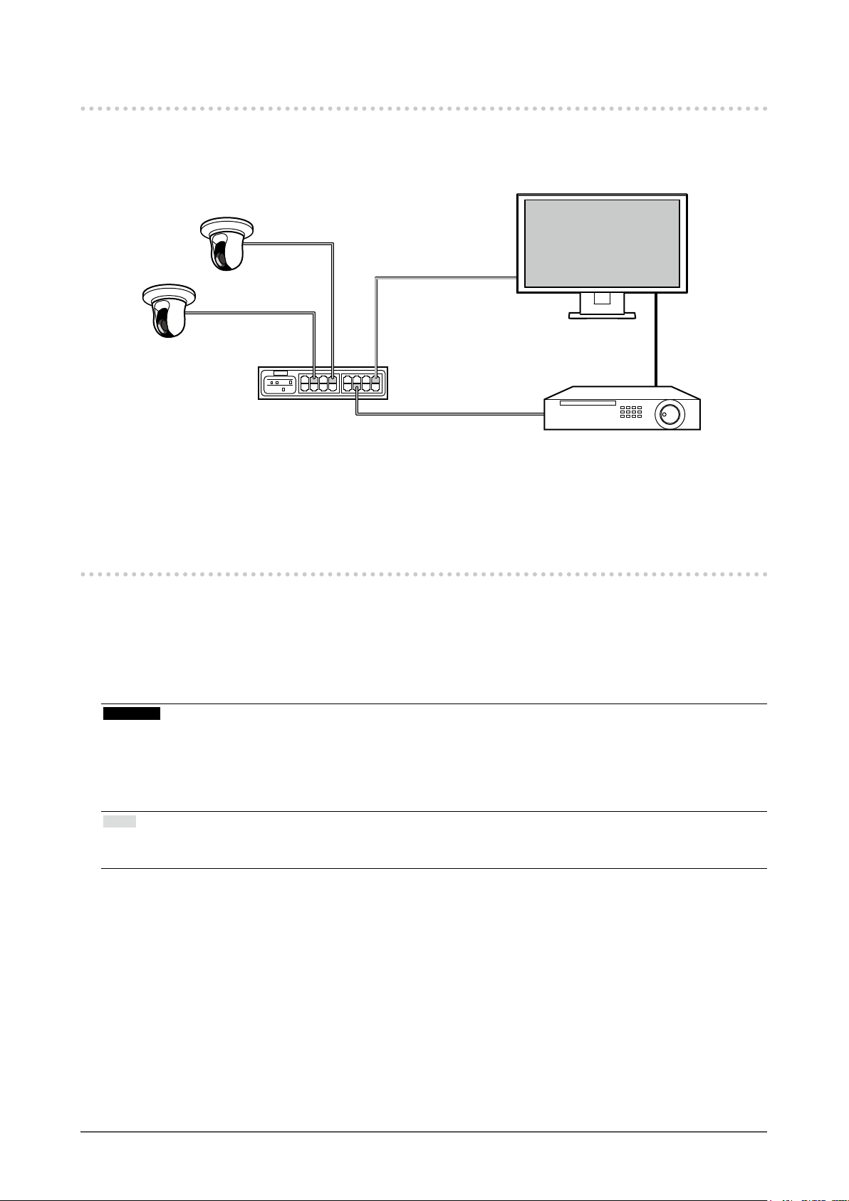
1-2. SystemConguration
Communicating with network cameras, it can display video on the monitor, and operate cameras.
FDF2304W-IP
Ethernet
Network camera
*1
Network hub
HDMI
HDMI device
(Network video recorder etc.)
*1 Up to 16 network cameras can be registered.
*2 Use an HDMI device (e.g. network video recorder) if necessary.
*2
1-3. Supported Network Cameras
This product supports the following network cameras:
• Panasonic i-pro series network cameras
• AXIS network camera
• ONVIF Prole S-compatible network cameras
Attention
• Supported network cameras vary depending on the monitor’s software version. Check the software version of
the monitor you are using, then check our website (http://www.eizoglobal.com) for details on supported network
cameras. For information on how to check the software version, refer to “2-6. Conguring System Settings” (page
26).
• For installation and settings of network cameras, also check the network camera’s manual.
Note
• You can access network camera images by specifying the URI to verity the network camera connections. For
details, see “Manual Registration of Cameras / Changing Camera Information” (page 50).
Chapter 1 Product overview
8
Page 9

Chapter 2 Conguringfromthemonitor
screen
You can congure and operate network cameras from the monitor screen. To congure from your web
browser, see “Chapter 3 Conguring from a Web Browser” (page 43). Operating and setting the monitor
can be implemented by using either the Remote Control, or a USB mouse. To use a USB mouse, connect
the mouse to the USB downstream port at the back of the monitor.
2-1. BeforeConguration
To congure from the monitor screen, you need to be logged in to the system.
Conguration of this product is allowed only by ADMIN level users.
Be sure to log in to the system with a user account of this level.
Procedure
1. Press
The power indicator lights up blue and the live image screen is displayed.
(For information on the live image screen, refer to the Instruction Manual.
2. Select (Login) under “System”.
The login screen is displayed.
3. Enter a username and a password.
4. Select “Login”.
The display changes back to the live image screen.
on the front of the monitor or on the remote control.
3
4
2
5
5. Select (Setting).
The setting screen is displayed.
(For information on the setting screen, see “2-2. Setting Screen” (page 10).
Note
• See “Entering characters” (page 11) for the character entry method.
• The following user information is set by default:
- Username: “admin”
- Password: “admin”
- User Level: “ADMIN”
• For information on user settings, see “2-7. Setting User Information” (page 36).
• It is recommended that you log out after completing the setup, so as to prevent a third party from operating
the network camera or altering the settings.
• When the Auto Login settings are congured, you can log in to the system without the username and
password. For details, see “Conguring Auto Login Settings” (page 40).
Attention
• When the monitor power is turned off while the user is logged in, the user is logged out from the system
automatically. In such a case, you cannot display the web interface in your web browser.
Chapter 2 Conguring from the monitor screen
9
Page 10
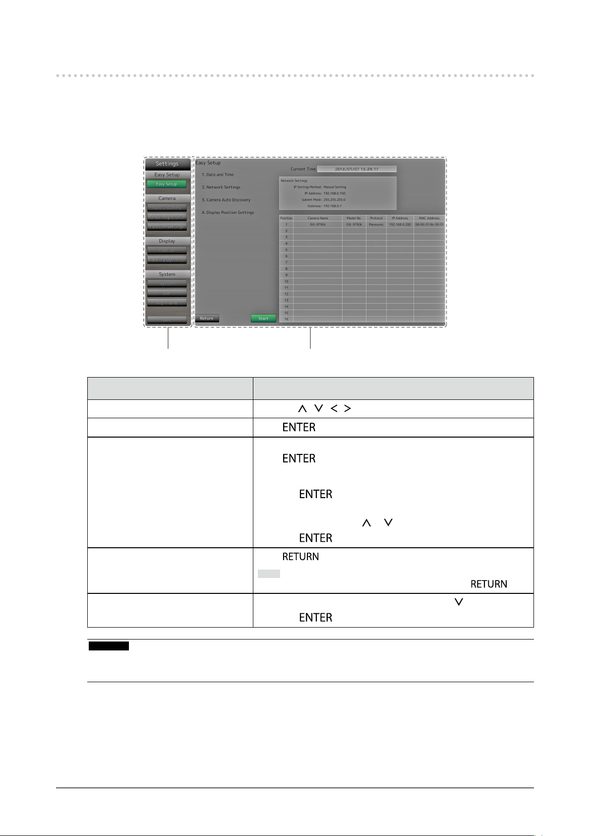
2-2. Setting Screen
The setting screen is used for various settings such as network camera registration and monitor system
settings.
Basic operations
●
List of setting items
The setting screen of the selected item is displayed.
Item Operation method
To select an item Press the
To conrm a selected item Press
To change a setting With setting buttons:
Press
With list box:
1. Press
The list box is highlighted in green.
2. Select the setting with
3. Press
To return to the previous menu level
To exit the setting screen
Press .
Note
• When canceling a setting change in process, press .
1. Select “Exit” from the list of setting items with
/ / / buttons.
.
. (Excluding zoom in / out and position adjustment)
.
.
2. Press .
or .
.
Attention
• While settings are being applied (registered) to the system, a “Setting” (“Registering”) message is displayed.
Do not turn off the monitor while the message is displayed. Otherwise, setting information may be lost.
Chapter 2 Conguring from the monitor screen
10
Page 11
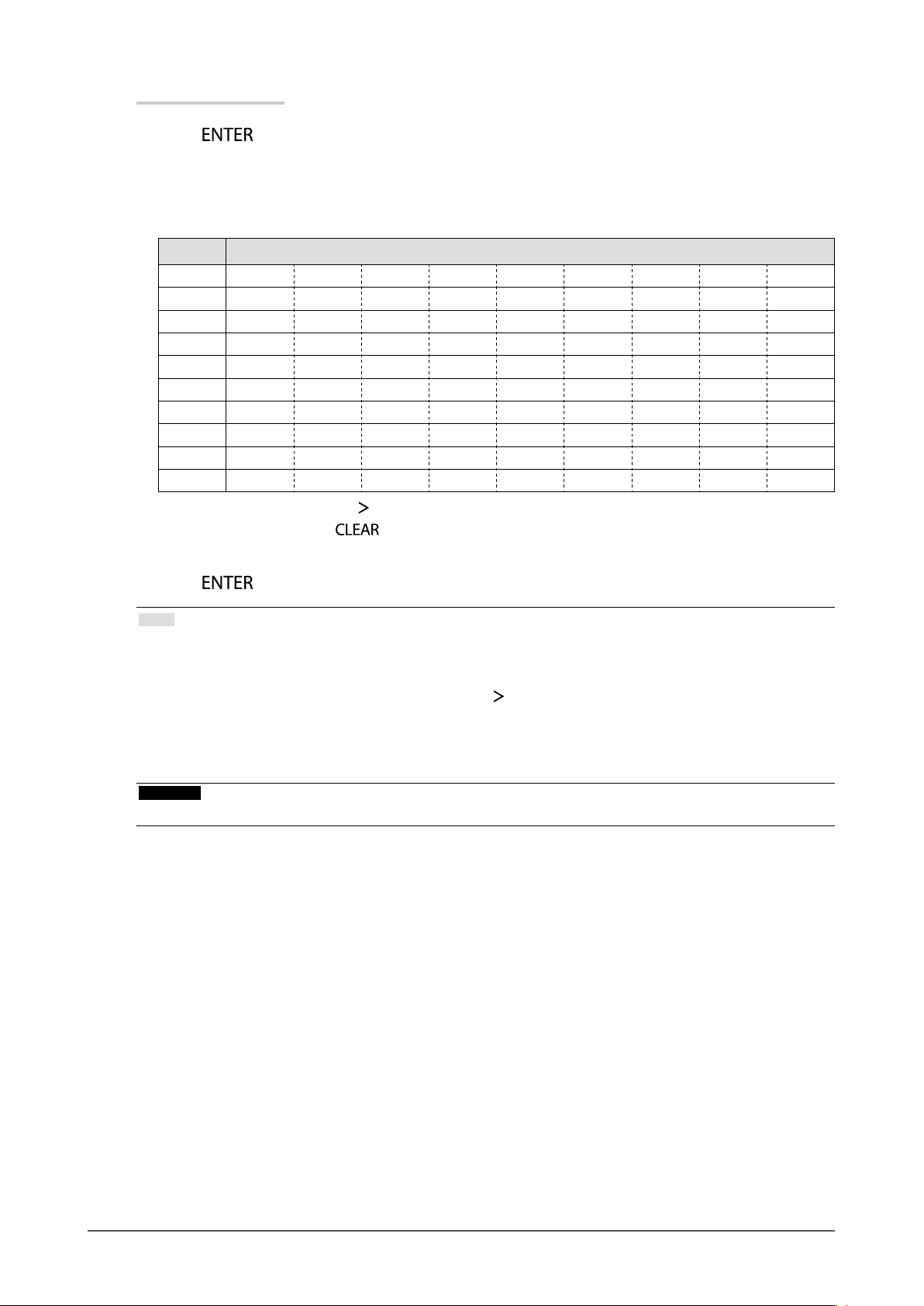
Entering characters
1. Press
The text eld is highlighted in green.
.
2. Press the number buttons ( 0 to 9 ).
Press a button consecutively to change over to the character next in order. For the order of character entry,
refer to the table shown below.
Button Input characters
0 0 - _ : . / (sp ac e)
1 1
2 a b c A B C 2
3 d e f D E F 3
4 g h i G H I 4
5 j k l J K L 5
6 m n o M N O 6
7 p q r s P Q R S 7
8 t u v T U V 8
9 w x y z W X Y Z 9
To enter a new character, press
To delete a character, press
3. Press
.
.
.
Note
• Entering network addresses
Network address text elds are separated by [.] (a period mark).
- When a three-digit number is entered, the cursor automatically moves to the next entry position.
- When entering a two-digit or one-digit number, press
• When using a USB mouse
- When you enter a period “.”, the cursor moves to the next entry position.
- To enter characters, click “Keyboard” on the character entry screen. Then click the keys on the displayed
keyboard to enter characters.
Attention
• The remote control cannot be used to select the character entry screen keyboard.
to move to the next entry position.
Chapter 2 Conguring from the monitor screen
11
Page 12

2-3. Setting Network Cameras
To automatically discover network cameras
●
Discover network cameras on the network automatically and register them to the system.
This procedure is for setting network cameras connected after performing “Easy Setup” upon initial
startup of the monitor.
Attention
• Only the network cameras installed in the same subnet as the monitor are detected. If a network camera is
installed in a different subnet, the camera must be registered manually (see “To manually register network
cameras” (page 15)).
• When network cameras are not detected by automatic discovery, see “Chapter 4 Troubleshooting” (page
78).
• For information on “Easy Setup”, refer to the Setup Manual.
Procedure
1. Select “Auto Discovery”.
2. Select “Camera Discovery” and press
3. Select the camera type using
Displays registered network cameras.
4. Select “Start” and press .
2
1
The camera user authentication screen is displayed.
5. Enter the “Username” and “Password” of the user who has administrator’s rights, specied in the
network camera.
The following values are entered as the default settings. Change the settings if necessary. Please contact
your system administrator for the username and password.
- Username: “admin”
- Password: “12345”
or , then press .
.
4
Chapter 2 Conguring from the monitor screen
12
Page 13
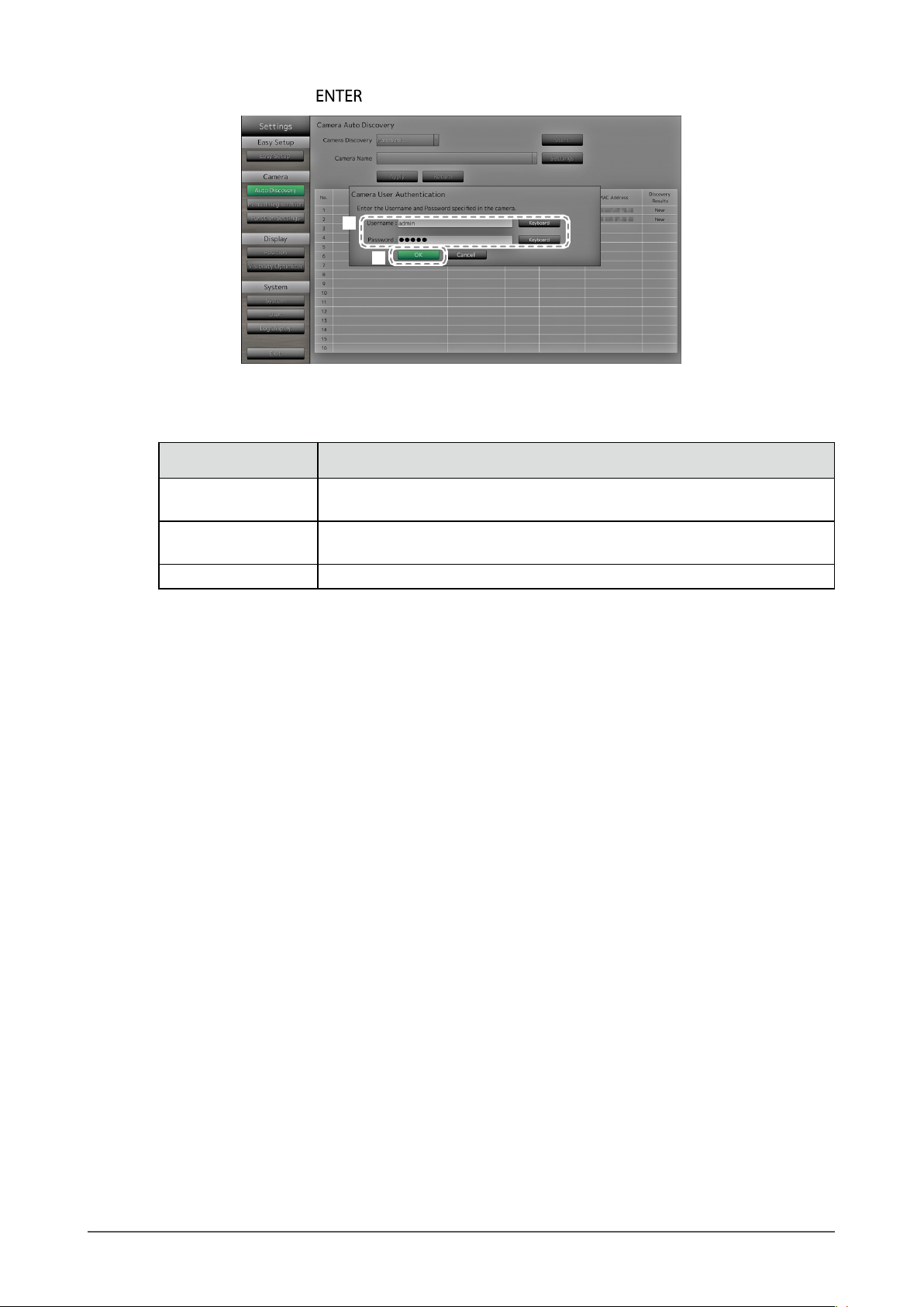
6. Select “OK” and press .
5
6
Automatic discovery is started and a “Searching” message is displayed. When the search is completed, the
discovered network cameras are added to the list. A subsequent result is displayed in the detection results
for camera discovery.
Discovery Results Description
Blank
New
Duplicate
When there is no information update for the registered network cameras,
or one is not connected
When there is an unregistered network camera, or information was
updated for a registered network camera
When there is a network camera with a duplicate IP address
Chapter 2 Conguring from the monitor screen
13
Page 14

7. Select “Apply”.
The setting complete screen is displayed. Select “OK”.
7
Note
Panasonic network camera
• The settings of the newly detected network camera can be changed.
Select the network camera whose settings you want to change at “Camera Name” and then select
“Settings”. Congure the items on the displayed setting screen. The items that can be set differ depending
on the network camera.
• When registered automatically, stream and channel for accessing the network camera are automatically
set to the following values. You can change the settings in “Manual Registration” (refer to “To manually
register network cameras” (page 15).) Please contact your system administrator for your username and
password to access the network camera.
- Stream: “2”
- Channel: “1”
- RS485 PTZ Control: “Off”
*1 Only set “RS485 PTZ Control” to “On” when connecting an external device to the network
camera using a RS485 cable.
AXIS network camera
• When executing automatic detection with an incorrect user name or password, “------” is displayed for the
model name.
• When a detected IP address is a duplicate of a registered network camera, but the username and
password are correct, ‘Model Name – MAC Address’ is displayed, and “------” is displayed for the model
name.
*1
Chapter 2 Conguring from the monitor screen
14
Page 15
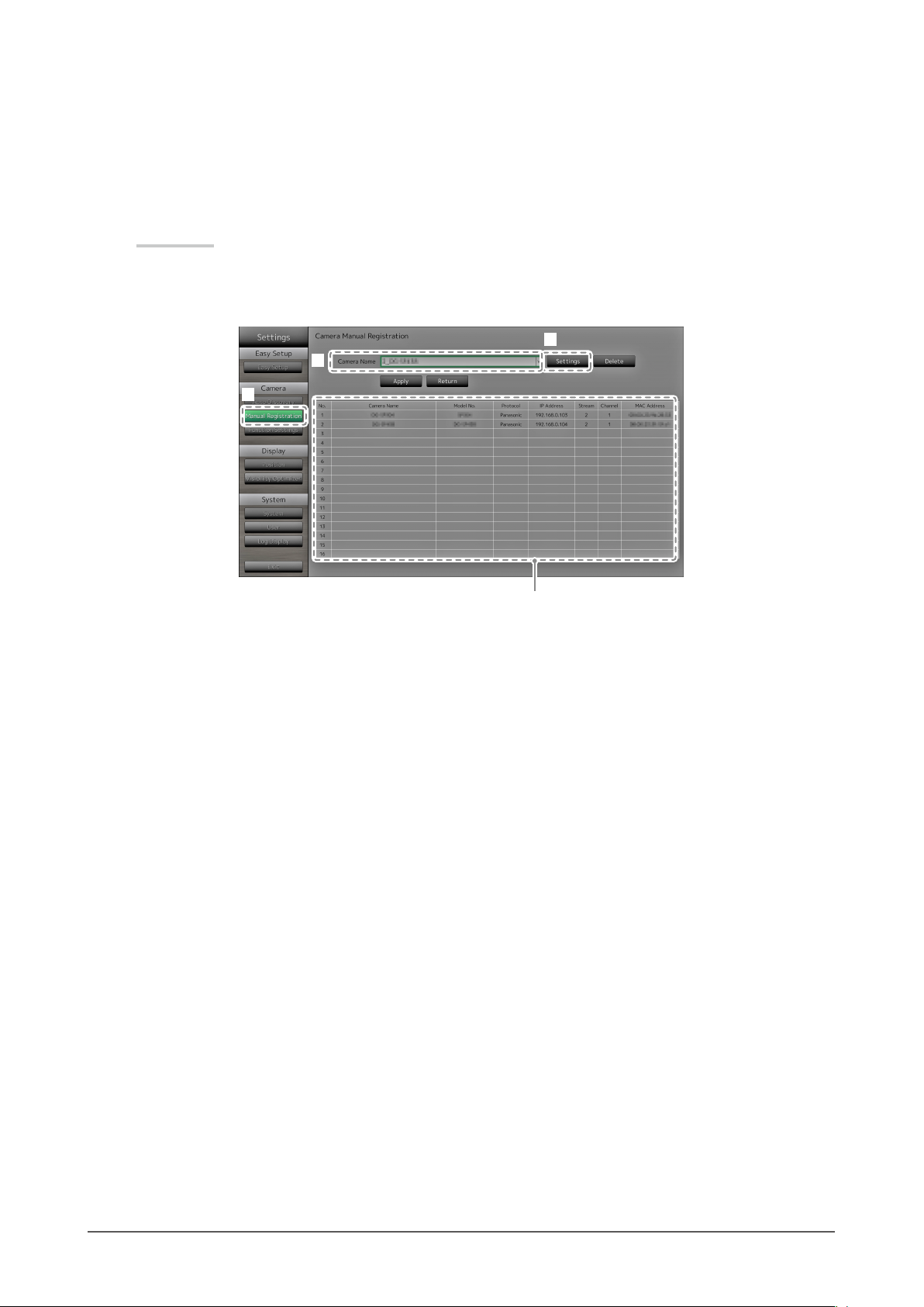
To manually register network cameras
●
Register network cameras manually for cases described below.
• When a network camera is installed in a subnet differing from the subnet of the monitor
• When settings such as network settings of a registered network camera have been changed
• When registering a video encoder which supports multiple channels
Procedure
1. Select “Manual Registration”.
A list of network cameras currently registered is displayed.
3
2
1
Registered cameras are displayed.
2. Select the network camera to congure at “Camera Name”.
When registering a network camera installed in a subnet differing from the subnet of the monitor, select an
available number (with no network camera registered). For a network camera that is already registered,
select the network camera of which to change settings.
3. Select “Settings”.
The network camera setting screen is displayed.
Chapter 2 Conguring from the monitor screen
15
Page 16
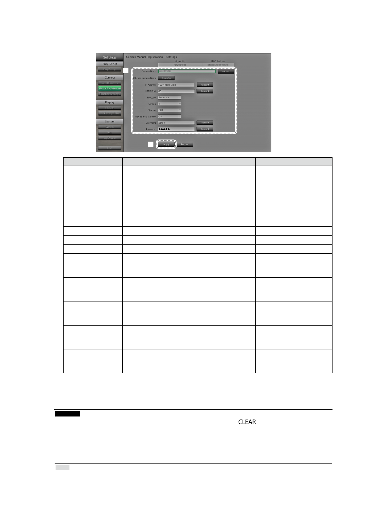
4. Congure the items.
For setting details, contact your system administrator.
4
5
Item Detail Setting range
Camera Name Enter the camera name. When selecting ‘Execute’
for ‘Obtain Camera Name,’ the camera name is
automatically obtained from the network camera.
• Panasonic network camera: Camera Name
• AXIS network camera: Camera Name
• Network camera compatible with the “ONVIF”
protocol: Camera model number, manufacturer
name, etc.
IP Address Enter the network camera IP address. 0.0.0.0 to 255.255.255.255
HTTP Port Enter the network camera HTTP port number. 1 to 65535
Protocol Select the protocol for controlling the camera. Panasonic / AXIS / ONVIF
*1
Stream
Set the number of the stream for delivering
camera images. Select a stream supported by the
connected network camera.
Channel
*1
Select the channel of the analog encoder. Set to "1"
if the network camera does not support the channel
function.
RS485 PTZ Control
*1
Controls the brightness, automatic focus adjustment,
pan, tilt and zoom for devices that are connected to
the network camera via a RS485 cable.
Username
*2
Enter the username to use when accessing network
cameras.
Password
*2
Enter the password to use when accessing network
cameras.
*1 Supported only when compatible with the Panasonic protocol.
*2 Enter the username with administrator rights and the password.
Alphanumeric characters
(up to 24 characters)
CH1 to CH4
CH1 to CH4
On / Off
Alphanumeric characters and
symbols
(up to 32 characters)
Alphanumeric characters and
symbols
(up to 32 characters)
5. Select “Apply”.
The setting complete screen is displayed. Select “OK”.
Attention
• If you want to change the set values using the remote control, press the button, then enter the values
(for details see “Entering characters” (page 11)).
• Depending on the network camera type, the “Model No.” displayed on the setting screen may differ from
when the camera is discovered automatically and when it is registered manually.
• Only set “RS485 PTZ Control” to “On” when connecting an external device to the network camera using a
RS485 cable.
Note
• With manual registration, network settings of a camera cannot be changed. When changing the network
settings of a camera, check the network camera’s manual.
Chapter 2 Conguring from the monitor screen
16
Page 17
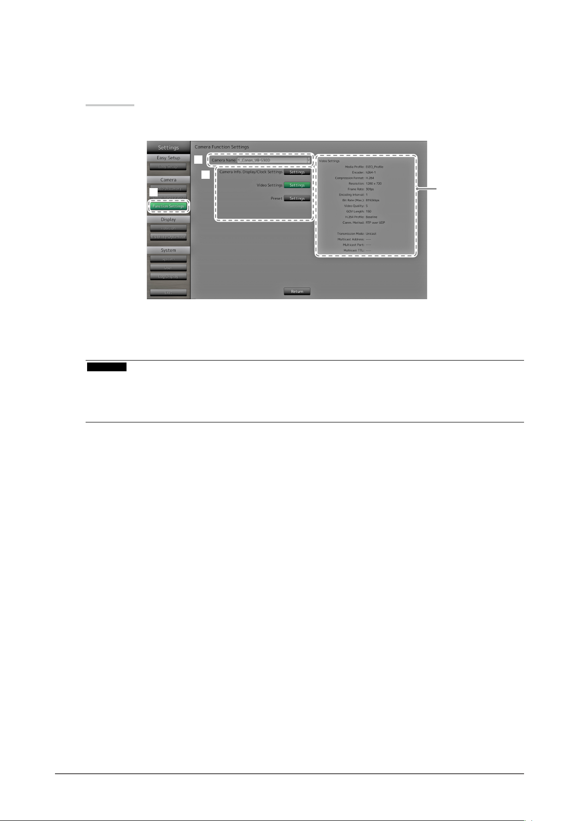
To set network camera functions
●
Set the network camera functions from the monitor.
Procedure
1. Select “Function Settings”.
2
3
1
2. Select the network camera to congure at “Camera Name”.
3. Select a function.
The setting screen for the selected function is displayed.
Attention
• The network camera set to “DirectUri” can be registered or congured only from the Web browser. It cannot
be registered or congured from the monitor screen. For the registration and conguration of the network
camera set to “DirectUri”, refer to “Manual Registration of Cameras / Changing Camera Information” (page
50).
Displays current
settings.
Chapter 2 Conguring from the monitor screen
17
Page 18
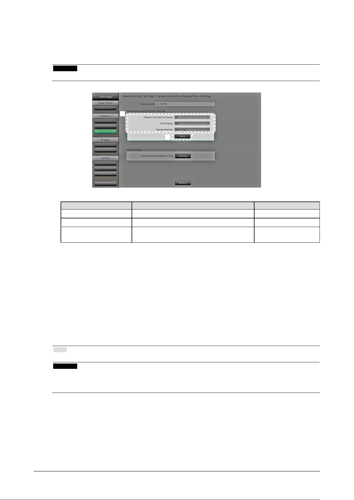
Camera Information Display
Select to display or not display the camera information and time of the network camera settings on
the camera images.
Attention
• It is not possible to congure the network camera when its “Protocol” is set to “ONVIF”,“AXIS”, or “DirectUri”.
1
2
1. Congure the items.
Item Detail Setting range
Camera Information Display Set whether or not to display camera information. On / Off
Time Display Set whether or not to display the time. 12h / 24h / Off
Display Position Set the display position of the camera information
and time.
Upper Left / Upper Right /
Lower Left / Lower Right
2. Select “Apply”.
The setting complete screen is displayed. Select “OK”.
Clock Settings
1. Synchronizes the time of the network camera with the time of the monitor.
Select “Execute” to synchronize the clock.
Video Settings
Set the Image Quality of transmitted images for the network camera.
Note
• This product supports H.264 and MJPEG (ONVIF only) video compression formats.
Attention
• When devices such as recorders are connected to a network camera, the display and recording of such
devices may be affected.
• It is not possible to congure the network camera when its “Protocol” is set to “DirectUri”.
Chapter 2 Conguring from the monitor screen
18
Page 19
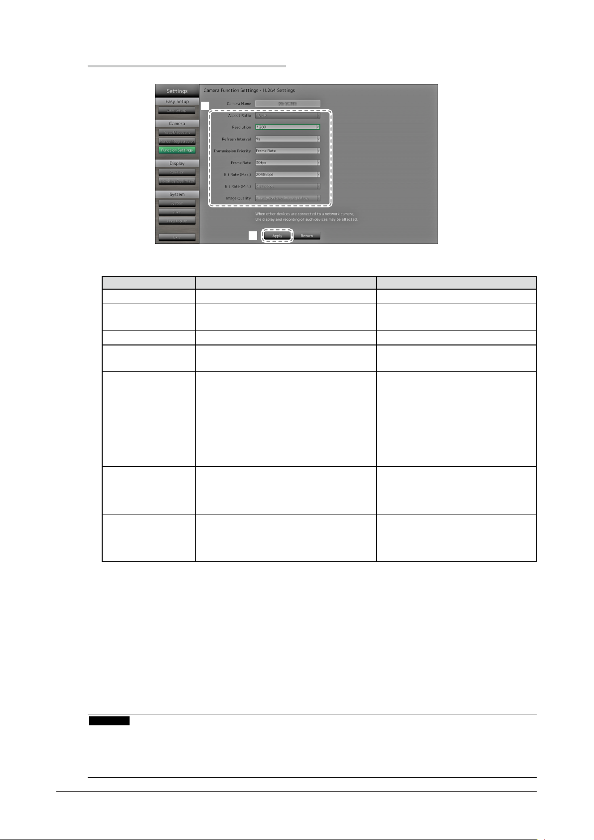
WhenusingaPanasonicnetworkcamera
1
2
1. Congure the items.
Item Detail Setting range
Aspect Ratio Set the H.264 aspect ratio.
Resolution Set the H.264 resolution. According to the network camera
Refresh Interval Set the refresh interval
Transmission Priority Set the transmission mode of H.264
images.
Frame Rate (When the mode is set to “Frame Rate” at
“Transmission Priority”.)
Set the frame rate (image update interval)
of H.264 images.
*3
Bit Rate (Max.) Set the maximum H.264 image bit rate.
Bit Rate (Min.) (When the mode is set to “Best Effort” for
“Transmission Priority”.)
Set the minimum H.264 image bit rate.
Image Quality (When the mode is set to “Constant Bit
Rate” or “Best Effort” for “Transmission
Priority”.)
Set the H.264 image quality.
*1 When “1920” is selected for “Resolution”, the aspect ratio is xed to 16:9. The aspect ratio cannot be
set when the network camera “Stream” is set to a value other than “1”.
*2 For H.264 images, the differential data between the full screen frame data and previous frame are
sent periodically. “Refresh Interval” refers to the interval for sending these full screen frame data.
Shortening this interval improves the stability of image quality but also increases the load on the
network. “Refresh Interval” refers to the interval at which the full screen data is transmitted. Shortening
this interval improves the image quality but also increases the load on the network.
*3 The shorter the interval, the shorter the update interval and the smoother the display, but also the larger
the load on the network.
*1
*2
of H.264 images.
Network camera imaging mode
specication
0.2s / 0.33s / 0.5s / 1s / 2s / 3s / 4s / 5s
Constant Bit Rate / Frame Rate / Best
Effort
1fps / 3fps / 5fps / 7.5fps / 10fps / 12fps /
15fps / 20fps / 30fps
64kbps / 128kbps / 256kbps / 384kbps /
512kbps / 768kbps / 1024kbps /
1536kbps / 2048kbps / 3072kbps /
4
096kbps / 8192kbps
64kbps / 128kbps / 256kbps / 384kbps /
512kbps / 768kbps / 1024kbps /
1536kbps / 2048kbps / 3072kbps /
4096kbps / 8192kbps
Low (prioritize motion) / Normal / Fine
(prioritize image quality)
2. Select “Apply”.
The setting complete screen is displayed. Select “OK”.
Attention
• To display the multicast stream of Panasonic network cameras, congure multicast on the camera.
• When you change the “Aspect Ratio,” the network camera imaging mode will change. Depending on the
imaging mode, the image quality of other recording devices or display devices may be impacted. Check the
impact of changes to the imaging mode before conguring the settings.
Chapter 2 Conguring from the monitor screen
19
Page 20

WhenusinganAXISnetworkcamera
1
2
1. Congure the items.
Item Detail Setting range
Video Stream Select the display mode for screens that display
network camera images.
Stream Prole Select the prole that the network camera has. According to the camera
Compression Format Select the compression format. H.264 (Fixed)
Resolution Set the resolution of H.264 images. According to the camera
Frame Rate Set the frame rate (image update interval) of
H.264 images.
Rotation
*1
Show the rotational direction of the network
camera image.
GOP Length Set the GOP length for video. I-frame Interval
Bit Rate (Max.) Set the maximum H.264 image bit rate. According to the camera
Priority Set the preference for video compression. None / Frame Rate / Quality
Transmission Mode Select the transmission method for AXIS
camera images.
Multicast Address*
2
Show the multicast address for multicast
transmission of H.264 images.
Multicast Port*
2
Show the multicast port number for multicast
transmission of H.264 images.
Multicast TTL*
2
Show the network TTL value for multicast
transmission of H.264 images.
*1 For details on rotation settings, refer to the network camera user’s manual.
*2 Displays when “Transmission Mode,” or “Multicast” is selected.
According to the camera
specication
specication
specication
According to the camera
specication (Maximum possible
values 30fps)
According to the camera
specication
(only when H.264 is selected)
specication (Maximum possible
values 8192 kbps)
Unicast / Multicast
224.0.0.0 to 239.255.255.255
1824 to 65534 even numbers
only
According to the camera
specication
2. Select “Apply”.
The setting complete screen is displayed. Select “OK”.
Attention
• To display the multicast stream of AXIS network cameras, congure multicast on the camera.
Chapter 2 Conguring from the monitor screen
20
Page 21

ONVIFProleS-compatiblenetworkcameras
1
2
1. Congure the items.
Item Detail Setting range
Media Prole Select the ONVIF image prole. EIZO_Prole / camera prole
Encoder Select the encoder settings of ONVIF images. According to the camera
specication
Compression Format Select compression format of ONVIF images. H.264 / MJPEG
Resolution Set the resolution of ONVIF images. According to the camera
specication
Frame Rate Set the frame rate (image update interval) of
ONVIF images.
Encoding Interval Set the encoder interval of ONVIF images. According to the camera
Bit Rate (Max.) Set the maximum ONVIF image bit rate. 0 to 8192 kbps
Video Quality Set the ONVIF image quality. The higher the
value, the higher the image quality.
GOV Length*
H.264 Prole*
1
1
Set the I-frame interval of ONVIF images. According to the camera
Select a H.264 standard prole. Baseline / Main / Extended / High
Transmission Mode Select the transmission format of ONVIF
images.
Multicast Address*
2
Set the multicast address for multicast
transmission of ONVIF images.
Multicast Port*
2
Set the multicast port number for multicast
transmission of ONVIF images.
Multicast TTL*
2
Set the network TTL value for multicast
transmission of ONVIF images.
*1 Displays when “H.264” is selected in “Compression Format”.
*2 Displays when “Multicast” is selected in “Transmission Mode”.
1 to 30 fps
specication
According to the camera
specication
specication
Unicast / Multicast
224.0.0.0 to 239.255.255.255
1824 to 65534 even numbers only
According to the camera
specication
2. Select “Apply”.
The setting complete screen is displayed. Select “OK”.
Attention
• Depending on the network camera type, some set values may not be reected. Check the specications of
the camera.
• When changes are made to the image quality settings such as resolution, this may impact on the image
quality of other recording devices and display devices using the same ”Encoder”. Check the impact of
changes to the image quality settings before conguring the settings.
Chapter 2 Conguring from the monitor screen
21
Page 22
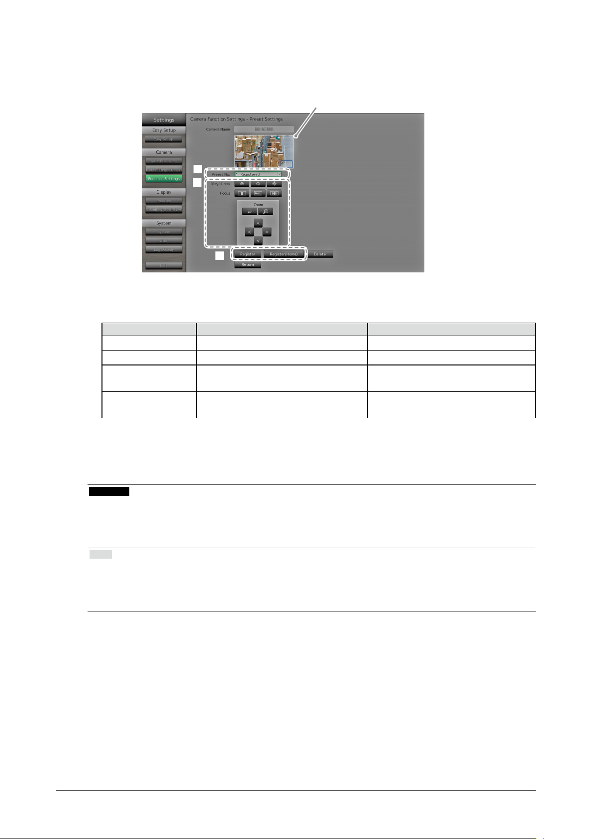
Preset
Preset the shooting position and adjustment status of the network camera.
Displays images of the selected network camera.
1
2
3
1. Select the number (1 to 256) to set for “Preset No”.
2. Congure the items.
Item Detail Setting range
Brightness Adjust the network camera brightness. According to the camera specication
Focus Adjust the network camera focus. According to the camera specication
Zoom Adjust the network camera display
magnication.
Position Adjust the network camera shooting
position (pan / tilt).
According to the camera specication
According to the camera specication
3. Select “Register (Home)” for registering the selected number as the home position. For all other
registrations, select “Register”.
The registration completion screen is displayed. Select “OK”.
Attention
• It is not possible to congure the network camera when its “Protocol” is set to “AXIS” or “DirectUri”. Set the
preset settings on the camera side.
• Depending on the type of the network camera you are using, some functions may not be available.
• Depending on the network camera type, it may not be possible to register the brightness and focus settings.
Note
• After the setting is registered, the number displayed at “Preset No.” changes from “Not Registered” to “Home”
or “Registered”.
• To clear a setting, select the number to clear at “Preset No.” and then select “Delete”. The data set for the
number is deleted and the number status returns to the unregistered state.
Chapter 2 Conguring from the monitor screen
22
Page 23
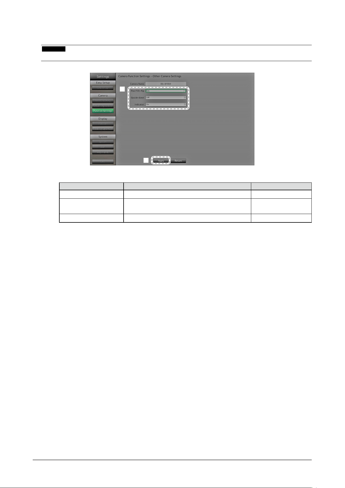
Other
Attention
• It is not possible to congure the network camera when its “Protocol” is set to “ONVIF”,“AXIS”, or “DirectUri”.
1
2
1. Congure the items.
Item Detail Setting range
Pan / Tilt-ip Turn on / off the pan / tilt-ip function*1. On / Off
Upside-down
Indicator Turn on / off the network camera Indicator. On / Off
*1 The pan / tilt-ip function reverses the pan / tilt direction automatically at high-speed when the network
camera reaches the movement endpoint. This function allows the user to make pan / tilt operations
without paying attention to movement endpoints.
*2 Check the network camera installation specications before using the upside down function.
Depending on the network camera type, it may not be possible to install the camera upside down even
when the camera supports the upside down function.
*2
Turn on / off the network camera upside down
function.
On / Off
2. Select “Apply”.
The setting complete screen is displayed. Select “OK”.
Chapter 2 Conguring from the monitor screen
23
Page 24
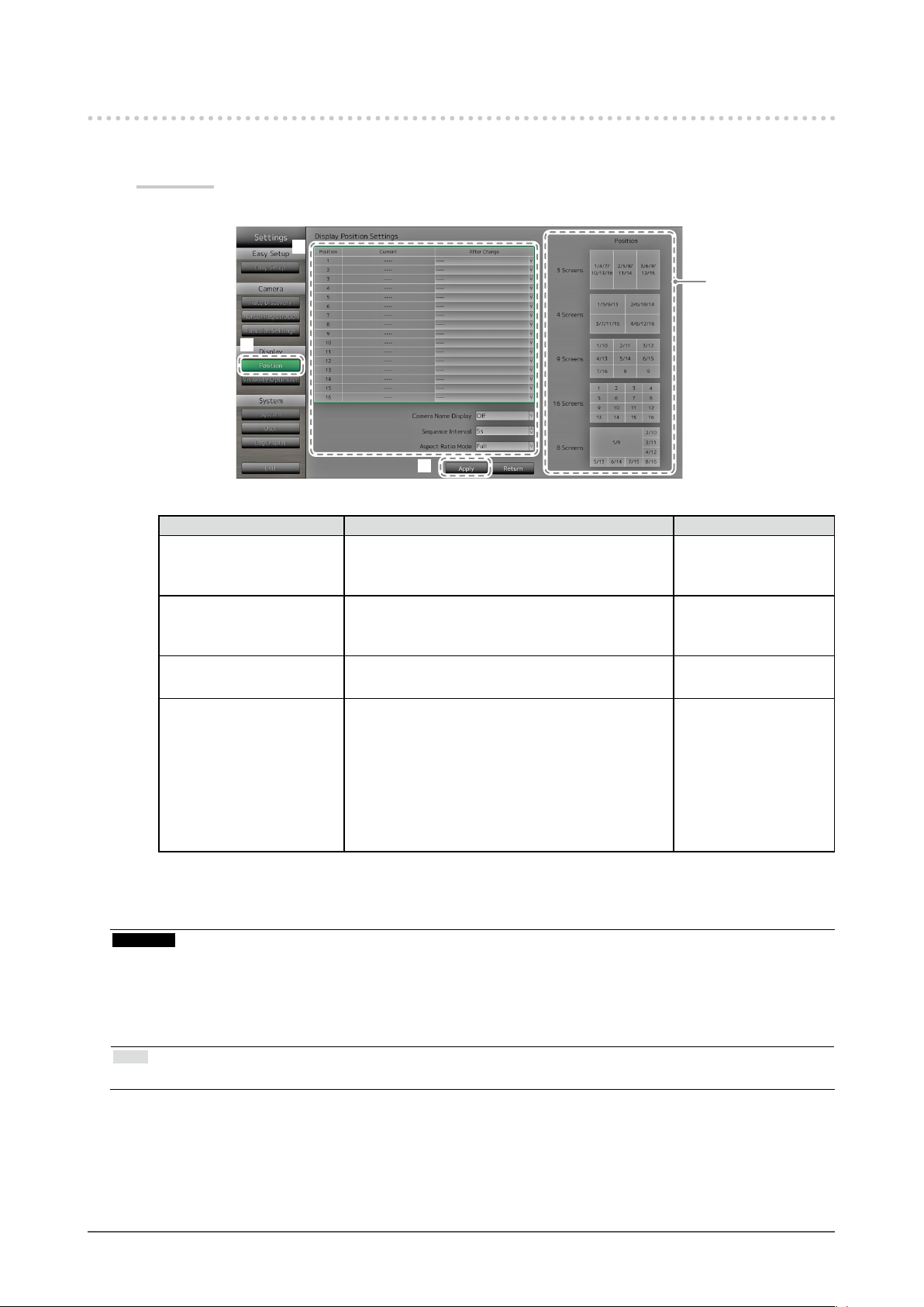
2-4. Setting Display Positions of Camera Images
Set the display position for images from the network camera.
Procedure
1. Select “Position”.
2
Indicates the
display positions
on the monitor
screen.
1
3
2. Congure the items.
Item Detail Setting range
Position Select a position to display a camera image.
Set the network camera to the number of the
desired position for display.
Camera Name Display Select to display or not display the camera name
and time set on the monitor. (The camera name is
displayed on the upper left of the image.)
Sequence Interval Set the interval for changing over the screen during
sequential display.
Aspect Ratio Mode Set which aspect ratio to apply when the aspect
ratio of the video delivered from the network
camera and the aspect ratio of the monitor image
display area differ.
If “Aspect” is selected when “Custom Screen” is
selected for the “Image Layout” (page 58), you
can select either “Full” or “Aspect” for each camera
image.
-
On / Off
5s to 60s
Full / Aspect
3. Select “Apply”.
The setting complete screen is displayed. Select “OK”.
Attention
• All registered network cameras must be congured. A network camera can only be set for one display position.
When there are incorrect settings, “Apply” cannot be selected.
• When displaying the image layout in three screens
- Suitable for portrait input images. To display portrait images, network cameras require separate settings. For
details on the settings, refer to the network camera User’s Manual.
Note
• If it takes a while for images to be displayed during sequential display, set a higher value for “Sequence Interval”.
Chapter 2 Conguring from the monitor screen
24
Page 25

2-5. Setting Visibility Optimizer Function
Set Visibility Optimizer function for images from each camera.
Procedure
1. Select “Visibility Optimizer”.
Displays images of the selected network camera.
2
1
3
4
Displays current
settings.
2. Select the network camera to congure at “Camera Name”.
Attention
• For 1 Screen or 4 Screens layouts the settings of each network camera are applied. If the image layout is
displayed in 3 Screens, 8 Screens, 9 Screens, or 16 Screens and if “Custom Screen” is selected, the “17_
Full Screen” settings are applied to all screens and the settings of each network camera are not applied.
3. Congure the items.
Item Detail Setting range
Mode Select the display mode to apply to the images of
the selected network camera.
Set to “DAY” to apply a mode suitable for general
images.
Set to “NIGHT” to apply a mode suitable for
monochrome images such as images taken at
night.
Outline Enhancer Adjusts the perceived resolution of the images
so that the blurs are reduced and images are
displayed vividly and clearly.
Low-light Correction Makes dark areas of images visible by analyzing
the image and correcting the brightness for each
pixel. It is effective for images with dark area that
are less visible and for bright environments.
Noise Reduction Reduces the amount of block noise that occurs due
to video compression.
DAY / NIGHT / Off
1 to 5 / Off
1 to 5 / Off
On / Off
4. Select “Apply”.
The setting complete screen is displayed. Select “OK”.
Chapter 2 Conguring from the monitor screen
25
Page 26
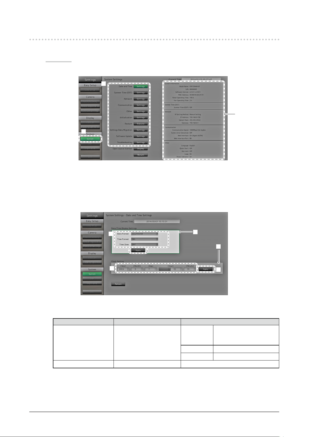
2-6. ConguringSystemSettings
Set the date, time and network information for this product.
Procedure
1. Select “System”.
2
1
2. Select a setting.
The setting screen for the selected setting is displayed.
Displays current
settings.
(e.g. software version)
Date and Time Settings
Set the current date and time.
2
2
1. Select “Date / Time Display Setting” or “Clock Setting”.
2. Congure the items.
Item Detail Setting range
Date / Time Display
Settings
Clock Setting Set the current time. 2010/1/1 0:00 to 2035/12/31 23:59
*1 Greenwich Mean Time
Set the date display format,
time display format, and time
zone (time difference between
*1
GMT
).
1
1
3
Date Format yyyy/mm/dd, Mmm/dd/yyyy,
dd/Mmm/yyyy, mm/dd/yyyy,
dd/mm/yyyy
Time Format 24h / 12h
Time Zone GMT-12:00 to GMT+14:00
Chapter 2 Conguring from the monitor screen
26
Page 27
3. Select “Apply”.
The setting complete screen is displayed. Select “OK”.
Attention
• Time zones differ according to the sales region. This needs to be set.
• If the time zone has been changed, daylight saving time will be turned off. (For details, refer to “Summer Time
(DST)” (page 27) in the next section).
Note
• If the main power switch is turned off or the power cord is unplugged for one week or longer, the monitor’s
time and date will no longer be displayed accurately. In such a case, set the date and time again.
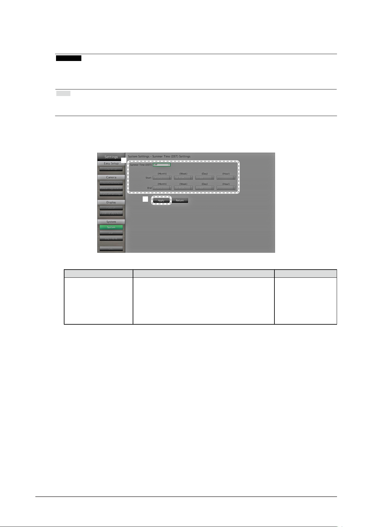
Summer Time (DST)
Apply or cancel the summer time setting (DST).
1
2
1. Congure the items.
Item Detail Setting range
Summer Time (DST) Applies or cancels the summer time setting.
Set to “On” to apply to summer time immediately.
Set to “Off” to not apply to summer time.
Set to “Auto” to apply to summer time automatically
during the period designated by the start / end dates
and times.
2. Select “Apply”.
The setting complete screen is displayed. Select “OK”.
On / Off / Auto
Chapter 2 Conguring from the monitor screen
27
Page 28
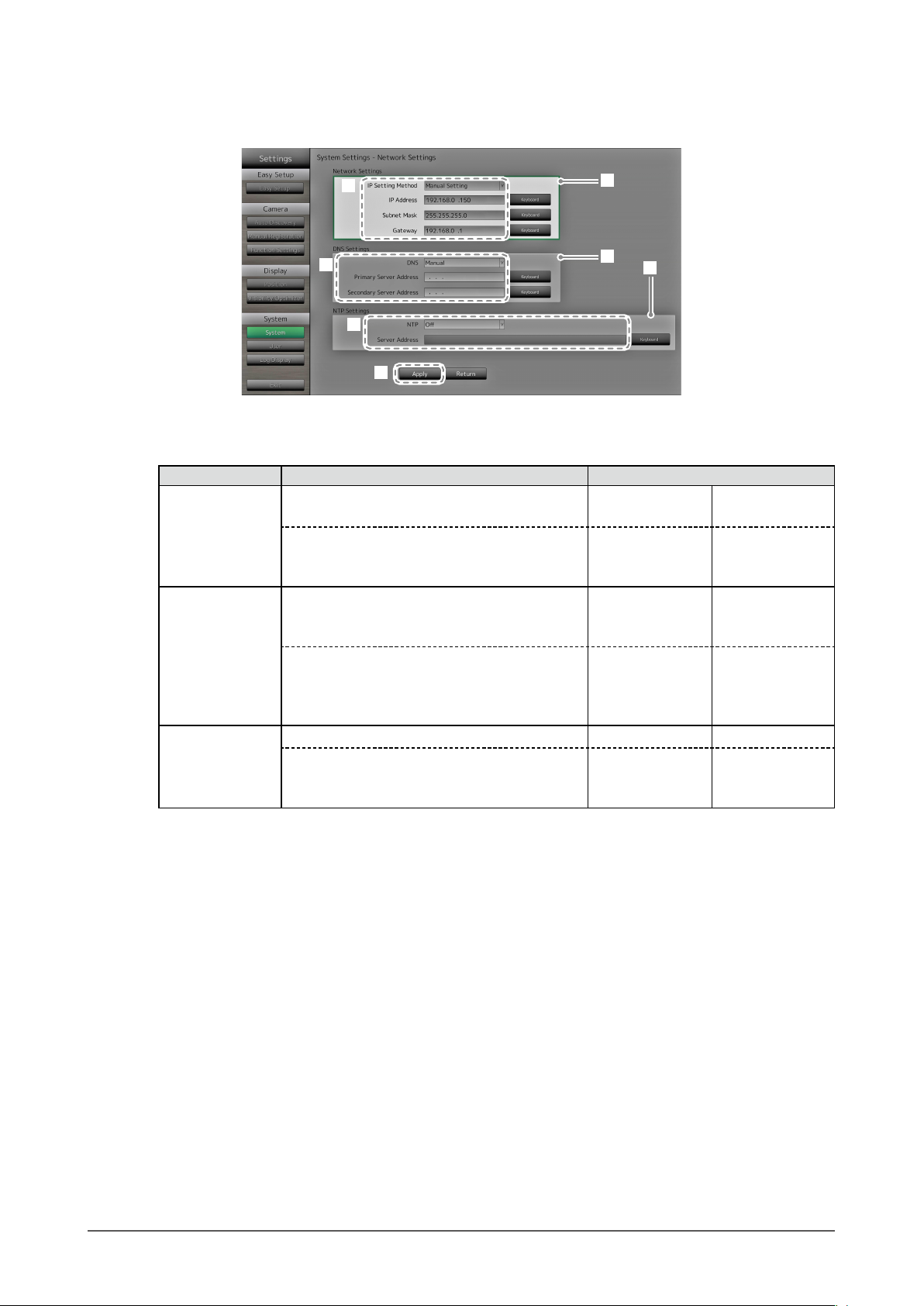
Network
Set network information.
2
2
2
3
1
1
1
1. Select “Network Settings”, “DNS Settings” or “NTP Settings”.
2. Congure the items.
Item Detail Setting range
Network Settings Select the IP address setting method. IP Setting Method DHCP / Manual
Setting
If “Manual Setting” is selected, set the IP
address, subnet mask and gateway.
DNS Settings Set the DNS.
(When “IP Address” of “Network Settings” is set
to “Manual Setting”.)
If you selected “Manual”, set the primary server
address and the secondary server address.
NTP Settings Set whether or not to use an NTP server. NTP On / Off
If you selected “On”, set the NTP server
address.
*1 If your network environment does not include a gateway, you do not need to set the “Gateway”
address. Use the default setting as is, or set as “0.0.0.0”.
IP Address,
Subnet Mask,
Gateway
DNS Auto / Manual
Primary Server
Address,
Secondary Server
Address
Server Address Alphanumeric
*1
0.0.0.0 to
255.255.255.255
0.0.0.0 to
255.255.255.255
characters and
symbols
3. Select “Apply”.
The setting complete screen is displayed. Select “OK”.
Chapter 2 Conguring from the monitor screen
28
Page 29
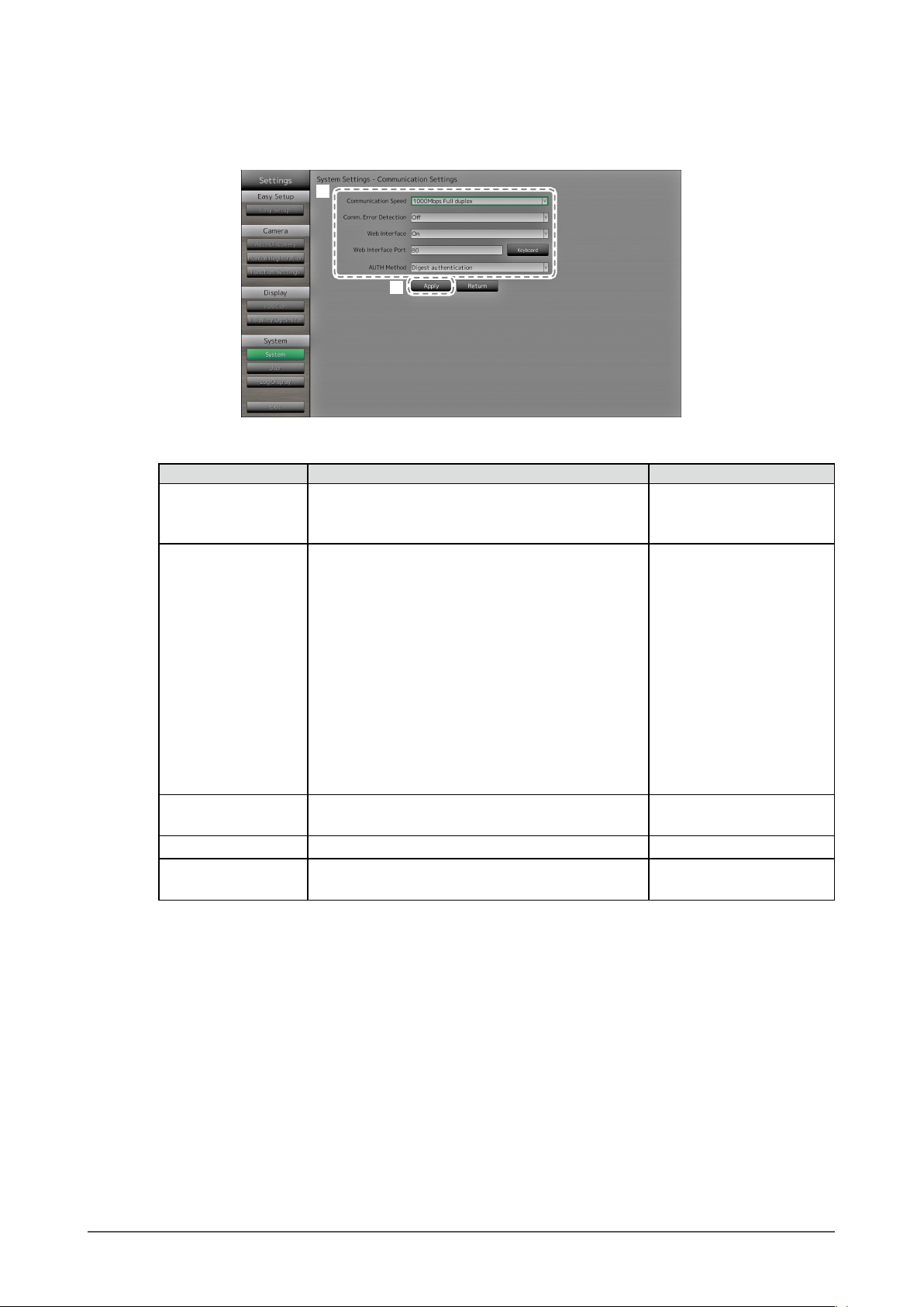
Communication Settings
The communication settings are used to congure the web interface function, detection of
communication errors, and so on.
1
2
1. Congure the items.
Item Detail Setting range
Communication speed Sets the communication speed between the monitor
and network hub.
Communication Error
Detection
You can set the following as the message to be
displayed when receipt of image data stops.
100Mbps Half duplex /
100Mbps Full duplex /
1000Mbps Full duplex
On / Off
Comm. Error Detection On:
Within several seconds after receipt of image data
stops, an alert message in a red box will appear
on the live image screen. When communication
resumes, the alert is cleared and the image is
displayed again.
Comm. Error Detection Off:
When approx. 20 seconds have elapsed after receipt
of image data stops, a communication error message
will appear.
Web Interface You can operate and congure the monitor from your
web browser over the network.
Web Interface Port Sets the port of the web interface. 1 to 65535
AUTH Method Sets the authentication method for the web interface. Digest authentication /
On / Off
BASIC authentication
2. Select “Apply”.
The setting complete screen is displayed. Select “OK”.
Chapter 2 Conguring from the monitor screen
29
Page 30

Other
1. Congure the items.
Item Detail Setting range
Language Set the display language of the menu and the setting screen.
Quick Start Set the status of the system when turned off.
1
2
When set to “On”, part of the system remains running.
When set to “Off”, the system is shut down completely.
/ English /
日本語
Deutsch / Polski
On / Off
*1
Key Lock Locks operations by the buttons on the front of the monitor. On / Off
Logo Set whether to display / hide the EIZO logo when the power
Power Indicator Set whether to turn of or off the power indicator (blue) while
*1 If “Polski” is selected for HDMI signal input, the display language is set to English.
*2 The rotating bar indicating that the system is starting up cannot be hidden.
2. Select “Apply”.
The setting complete screen is displayed. Select “OK”.
Initialization
Initialize the system.
By setting to “On”, the startup time for this product can be
reduced (approx. 10 seconds). However, do not turn off the
main power of the monitor when Quick Start is set to “On”
because part of the system remains running.
is turned on
the monitor is on.
*2
.
1
On / Off
On / Off
1. Select “Execute” for “Initialization”.
All settings are returned to default except for system logs, operation logs, the current time, time zone and
summer time settings.
Chapter 2 Conguring from the monitor screen
30
Page 31

Restart
Restart the system.
1. Select “Execute” at “Restart”.
Settings Data Migration
You can save the settings data to a USB storage device and load the data.
Load Settings Data
2
3
4
5
1. Connect a USB storage device to the USB downstream port of the monitor.
2. Select the settings data le.
3. Enter the password.
The password is blank by default. Set the password as necessary.
4. Select “Execute”. The settings data are loaded.
5. Select “Run” for “Remove USB Storage”.
When the Removing Complete screen is displayed, select “OK”.
6. Remove the USB storage device.
Attention
• The settings data include the IP address of the monitor. Change the IP address of the monitor if loading
settings data from another monitor.
Chapter 2 Conguring from the monitor screen
31
Page 32

Save Settings Data
1. Connect a USB storage device to the USB downstream port of the monitor.
2
3
4
2. Enter the password.
The password is blank by default. Set the password as necessary.
3. Select “Execute”. The settings data are saved.
4. Select “Run” for “Remove USB Storage”.
When the Removing Complete screen is displayed, select “OK”.
5. Remove the USB storage device.
Attention
• Some of the settings cannot be saved.
• If you forget the password that you specied when saving the data, you will no longer be able to load the settings.
Note
• Saved le name: Backupyyyymmdd.duraconf (yyyymmdd is the save date)
Chapter 2 Conguring from the monitor screen
32
Page 33

Software Update
You can select update les from the File Selection screen, and can both upgrade or downgrade
software.
1. Download the update le from the EIZO website (http://www.eizoglobal.com), and save it to a USB
storage device.
2. Connect a USB storage device to the USB downstream port of the monitor.
The File Selection screen is displayed.
USB downstream port
3
4
3. Select the update le.
4. Select “Execute”.
5. The message saying “You must restart the system to update the software. Remove the USB
storage and restart.” appears.
Remove the USB storage device.
6. Select “Restart” to restart the system.
The software is updated.
Attention
• Do not turn off the power while the software is being updated.
• You cannot operate the remote control and
software is being updated.
• The following USB storage devices can be used with this product (This does not guarantee operation of the
USB storage devices given below).
- USB 2.0 standard ash drives
- Supported format: FAT32
• Do not connect multiple USB storage devices simultaneously.
Note
• When you restart your system, a message indicating the success or failure of the software update will appear.
The message will clear automatically after 60 seconds if “OK” is not clicked. However, this message will not
appear if you do the update through your web browser.
and buttons on the front of the monitor while the
Chapter 2 Conguring from the monitor screen
33
Page 34

Troubleshooting
Use this function when this product does not operate normally, such as when a connection cannot be
established with a network camera or a communication error occurs. The network status can be
checked using communication commands and past error contents can be checked by displaying the
system log. In addition, system log data can be saved to a USB storage device.
Checking network connection status
2
3
1
Displays the
connection check
results.
1. Select “Connection Conrmation”.
2. Select the network camera to check the network connection of for “Camera Name”.
3. Select “Run” for “ping” or “traceroute”.
Results are displayed in the area on the right side of the screen.
Displaying the system log
2
3
1
1. Select “System Log”.
2. Select the date (year / month / day) to display the log data of.
3. Select “Run” for “Display”.
The log data is displayed in the area on the right side of the screen.
Displays the log.
Chapter 2 Conguring from the monitor screen
34
Page 35

Saving system log data
1. Connect a USB storage device to the USB downstream port on the back of the monitor.
USB downstream port
Displays the data
storage status.
3
2
4
5
2. Select “System Log”.
3. Select the date (year / month / day) of the log data to display.
4. Select “Run” for “Save to USB Storage”.
Data saving starts and a “Saving” message is displayed in the display area on the right side of the screen.
When the saving complete screen is displayed, select “OK”.
5. Select “Run” for “Remove USB Storage”.
When the removing complete screen is displayed, select “OK”.
6. Remove the USB storage device.
Attention
• The following USB storage devices can be used with this product (This does not guarantee operation of the
USB storage devices given below).
- USB 2.0 standard ash drives
- Supported format: FAT32
• Do not connect multiple USB storage devices simultaneously.
Chapter 2 Conguring from the monitor screen
35
Page 36

2-7. Setting User Information
Register, change or delete information (username, user level and password) on users that access this
product, and congure Auto Login settings.
Attention
• User information can be registered for up to 10 users. User information for a new user cannot be registered when
there are already 10 users registered.
• Duplicate usernames cannot be registered.
• At least one user with a user level of “ADMIN” must be registered.
• You can use alphanumeric characters for the username, however, the following character is not allowed: “ : “.
Note
• There are three user levels: “ LIVE”, “CAMERA CONTROL” and “ADMIN”.
The operable range of this product differs by each level.
(√: Operable, -: Inoperable)
Operation
Level
LIVE √ √ √ √ √ - CAMERA CONTROL √ √ √ √ √ √ ADMIN √ √ √ √ √ √ √
• The following user information is set by default:
- Username: “admin”
- Password: “admin”
- User Level: “ADMIN”
• User information settings or Auto Login settings can be returned to default settings according to the following
procedure. Use this feature, for example, when you have forgotten the registered user information.
1. Press
2. Press the buttons on the remote control in the following order (press the next button within ve seconds).
→ → → → → →
When the reset conrmation screen is displayed, select “Execute”.
User information is cleared and the settings are returned to the default settings.
on the remote control to turn off the monitor.
Menu
display
Layout
change over
Page
change over
Visibility
Optimizer
function
on / off
Login
operation
Camera
control
settings
System
Chapter 2 Conguring from the monitor screen
36
Page 37

To register new user information
●
Procedure
1. Select “User”.
2. Select “Settings” on the “User Info. Settings” screen.
2
1
3. Select “New User Registration”.
4. Set user information.
5. Select “Register”.
4
5
The registration completion screen is displayed. Select “OK”.
3
Chapter 2 Conguring from the monitor screen
37
Page 38

To change user information
●
Procedure
1. Select “User”.
2. Select “Settings” on the “User Info. Settings” screen.
2
1
3. Select “Change / Delete User Information”.
4. Set user information.
5. Select “Change”.
4
5
The registration completion screen is displayed. Select “OK”.
3
Chapter 2 Conguring from the monitor screen
38
Page 39

To delete user information
●
Procedure
1. Select “User”.
2. Select “Settings” on the “User Info. Settings” screen.
2
1
3. Select “Change / Delete User Information”.
4. Select the user to delete at “Username”.
5. Select “Delete”.
4
The deletion completion screen is displayed. Select “OK”.
3
5
Chapter 2 Conguring from the monitor screen
39
Page 40

ConguringAutoLoginSettings
●
Attention
• Once the Auto Login settings are congured, unauthorized operation becomes easy for a malicious third
party. Restrict the conguration to the application in an environment where sufcient security is ensured.
Procedure
1. Select “User”.
2. Select “Settings” on the “Auto Login Settings” screen.
2
1
3. Congure the items.
Item Detail Setting range
Auto Login Apply / release the Auto Login.
Set to “On”, and you can log in to the system without the
username and password.
Username Specify users to whom the Auto Login is to be applied. Registered username
User Level The user level is displayed for a user set under the
“Username”.
4. Select “Apply”.
The setting complete screen is displayed. Select “OK”.
On / Off
ADMIN / CAMERA
CONTROL / LIVE
Chapter 2 Conguring from the monitor screen
40
Page 41

2-8. Displaying Operation Logs
Operations of this product are recorded on logs. Past operation results can be checked by displaying the
log. Also, log data can be saved to a USB storage device.
Note
• The following data are recorded on the log:
- Login information: The names of users who logged in to the system
- Camera operation results: Name of operated camera, operation details, operation results
- Date, time and details of changes conrmed by selecting “Apply” on setting screens
• Logs older than two months are automatically deleted at 04:00:00 AM on the rst day of every month.
To display log data
●
Procedure
1. Select “Log Display”.
2
3
Displays the log.
1
2. Select the date (year / month / day) to display the log data of.
3. Select “Run” for “Display”.
The log data is displayed in the area on the right side of the screen.
Chapter 2 Conguring from the monitor screen
41
Page 42

To save log data
●
Procedure
1. Connect a USB storage device to the USB downstream port on the back of the monitor.
USB downstream port
2. Select “Log Display”.
3
Displays the data
4
5
storage status.
2
3. Select the date (year / month / day) of the data to save.
4. Select “Run” for “Save to USB Storage”.
Data saving starts and a “Saving” message is displayed in the display area on the right side of the screen.
When the saving complete screen is displayed, select “OK”.
5. Select “Run” for “Remove USB Storage”.
When the removing complete screen is displayed, select “OK”.
6. Remove the USB storage device.
Attention
• The following USB storage devices can be used with this product (This does not guarantee operation of the
USB storage devices given below).
- USB 2.0 standard ash drives
- Supported format: FAT32
• Do not connect multiple USB storage devices simultaneously.
Chapter 2 Conguring from the monitor screen
42
Page 43

Chapter 3 ConguringfromaWebBrowser
This product allows you to congure and operate network cameras from your web browser. Basic
Information, Monitor Settings, and the Live Image Screen Settings are located on the Web control screen.
Note
• To congure from the monitor screen, see ”Chapter 2 Conguring from the monitor screen” (page 9).
Attention
• It is recommended you use Internet Explorer 11 as your web browser.
• If you congure settings from a web browser, you will need to start up the monitor.
• You cannot display the web interface in your web browser when the monitor web interface is disabled in the settings
(For details, see “Communication Settings” (page 63)).
3-1. BeforeConguration
To congure settings from a web browser, you need to log in from the web browser you are using. Login
is allowed only when the level of the user accessing the product is ADMIN.
Procedure
1. Press
The power indicator lights up blue and the live image screen is displayed.
(For information on the live image screen, refer to the Instruction Manual.)
on the front of the monitor or on the remote control.
2. Display the web browser on your PC.
3. Enter the following address to access.
Address: http://Address of the monitors/ui
*1 The default address for access is http://192.168.0.150/ui.
The login screen is displayed.
*1
4. Enter a username and a password.
5. Select “OK”.
Displays the Web Control Screen.
Note
• The following user information is set by default:
- Username: “admin”
- Password: “admin”
- User Level: “ADMIN”
• For information on user settings, see “2-7. Setting User Information” (page 36).
• It is recommended that you log out after completing the setup, so as to prevent a third party from operating
the network camera or altering the settings. Exit the web browser.
Chapter 3 Conguring from a Web Browser
43
Page 44

3-2. WebControlScreen
Basic Information, Monitor Settings, and the Live Image Screen Settings are located on the Web control
screen.
Basic Information display lists of the various settings acquired from the monitor. The Monitor Settings are
used for various settings such as network camera registration and monitor system settings. Live Image
Screen Settings are used for displaying live image screen layout changes and the like.
Basic Operations
●
To select a setting item
• Click a setting item.
When you select a setting item, it will be displayed in green. In the case of a list box, when you
select a list item, it will be displayed in green.
To apply a setting item
• Click “Apply” or “Register”.
A “Setting Complete” or “Setting Failed” message is displayed. Click “OK” as required.
To exit the web browser
• Click
Note
• If auto discovery is in progress on the monitor, or the setting dialog box is displayed in the browser, operations
in the web browser will not be accepted. The busy message appears. Click “OK” to congure the settings
again.
in the web browser. This exits the browser.
Chapter 3 Conguring from a Web Browser
44
Page 45

3-3. Basic Information
Display lists of the various settings acquired from the monitor.
To make various settings, click to item tab at the top of the screen. This moves you to the setting items
page.
System Information
●
Displays the current status of the monitor system.
• Model Name
• S / N
• Software Version
System Status
●
Shows the monitor screen display status and brightness.
For this setting, click the link to “System Status Settings” or click “System Status” on the upper part of
the screen. This moves you to the setting items page.
Chapter 3 Conguring from a Web Browser
45
Page 46

Camera and Display Position / Date and TimeSettings / Network
●
Settings / Communication Settings
Displays the current settings status of the monitor.
To congure settings, click the link for the item name under an item, or click on the setting items tab
at the top of the screen. This moves you to the setting items page.
Chapter 3 Conguring from a Web Browser
46
Page 47

3-4. Setting Network Cameras
“Camera Registration” is used to display a list of the network cameras currently registered for a monitor.
You can add or change network cameras, and reect network camera information, etc., onto the monitor.
Attention
• You can only change network cameras that are registered.
• This cannot be used to set network camera functions. For information on setting network camera functions, see
“Chapter 2 Conguring from the monitor screen” (page 9).
To automatically detect cameras
●
Discover network cameras on the network automatically and register them to the system.
Attention
• Only the network cameras installed in the same subnet as the monitor are detected. If a network camera is
installed in a different subnet, the camera must be registered manually (see “To manually register network
cameras” (page 15)).
• For information on “Easy Setup”, refer to the Setup Manual.
Note
• The remaining number of network cameras that can be added for registration is displayed at the top of the
camera detection screen.
Procedure
1. Select “Camera Registration”.
A screen displaying a list of the camera registration information appears.
Chapter 3 Conguring from a Web Browser
47
Page 48

2. Select “Auto Discovery”.
A “Camera detection will start” dialog box appears.
3. Select the “Protocol” from the list.
Enter the “Username” and “Password” registered in the network camera.
4. Select “OK”.
A “Searching...” dialog box appears, and the detected network cameras are displayed in the list of additional
candidates.
Note
• There is a web page link in the web page eld of the list of detected cameras. When you click a link, a
camera web page will open in a separate window. (Address: http://(IP address):(HTTP port))
• If there are zero candidates in camera detection, nothing will display.
• If “Cancel” is selected during camera detection, a list of cameras detected up to the time of canceling will
be displayed.
5. Select a camera to be added from the list of candidates, and select “Add”.
Returns to the camera registration information list screen in step 1.
6. Select “Apply”.
A setting conrmation dialog box appears.
7. Select “OK”.
Chapter 3 Conguring from a Web Browser
48
Page 49

Load camera information
●
Importing a CSV le with the additional candidates for cameras, they can be the candidates for the
network cameras discovery.
Procedure
1. Select “Camera Registration”.
A list of camera registration information appears.
2. Select “Load camera information”.
A le dialog box opens
3. Select the CSV le that describes the network camera information, and select “Open.”
A list of the candidate network cameras appears.
4. Select a camera to be added from the list of candidates, and select “Add”.
Returns to the camera registration information list screen in step 1.
5. Select “Apply”.
A setting conrmation dialog box appears.
Chapter 3 Conguring from a Web Browser
49
Page 50

6. Select “OK”.
Note
• Up to 255 candidate cameras can be read.
• The CSV les that can be read are as follows.
- CSV les that are exported from the monitor or browser
- CSV les created by the user
• For details on how to export CSV les, refer to “Save Camera Information” (page 53).
• When a user creates a CSV le, the following rules apply.
- In line 1, enter the following as the item line: “CameraName, Protocol, IPAddress, Port, UserName,
PassWord, Uri, Comm.Method”.
- The columns are in random order.
- Input of the “UserName, PassWord, Uri, Comm.Method” values is user-dened.
- Only the specied string can be read for an item name.
Manual Registration of Cameras / Changing Camera Information
●
You can manually register cameras or modify registered information contents for cameras listed in the
camera registration information list.
Attention
• If multiple selections are made for registration information of a network camera to be changed, “Manual
Registration” will be disabled.
Procedure
1. Select “Camera Registration”.
A screen displaying a list of the camera registration information appears.
2. Put a check on the number of the camera to be registered or modied.
Chapter 3 Conguring from a Web Browser
50
Page 51

3. Select “Manual Registration”.
A “Camera Information Settings” dialog box appears. When a registered camera is selected, a dialog box
describing the applicable camera information appears.
Item Detail Setting range
Camera Name Enter the camera name. When “Obtain Camera
Name” is selected, the camera name is
automatically obtained from the network camera.
• Panasonic network camera: Camera Name
• AXIS network camera: Camera Name
• Network camera with its “Protocol” set to
“ONVIF”: Camera model number, manufacturer
name, etc.
IP Address Enter the network camera IP address. 0.0.0.0 to 255.255.255.255
Port Enter the network camera port number. 1 to 65535
Protocol Select the protocol for controlling the camera. Panasonic / AXIS / ONVIF /
Username
*2
Enter the username to use when accessing
network cameras.
Password
*2
Enter the password to use when accessing
network cameras.
*3
Stream
Select a stream for delivering camera images.
Select a stream supported by the connected
network camera.
Channel
*3
Select the channel of the analog encoder. If the
network camera does not support the channel
function, set to “1”.
RS485 PTZ Control
*3
Controls the brightness, automatic focus
adjustment, pan, tilt and zoom for devices that are
connected to the network camera via a RS485
cable.
Video Stream
*4
Select the display mode for screens that
display the network camera images. When
“Obtain Stream” is selected, the display mode is
automatically selected from the network camera.
Alphanumerics, kana, and
kanji (24 characters max.)
*1
DirectUri
Alphanumeric, symbols
(up to 32 characters)
Alphanumeric, symbols
(up to 32 characters)
CH1 to CH4
CH1 to CH4
On / Off
According to the camera
specication
Chapter 3 Conguring from a Web Browser
51
Page 52

Stream Prole
*4
Select the prole that the network camera has.
When “Obtain Prole” is selected, the prole is
According to the camera
specication
automatically selected from the network camera.
Media Prole
*5
Select the ONVIF image prole. When “Obtain
EIZO_Prole / camera prole
Prole” is selected, the prole is automatically
selected from the network camera.
Transmission Mode
*7
URI
*6
Select the transmission mode for camera images. Unicast / Multicast
Set the URI that starts with rtsp:// or rtp://. Alphanumeric
(up to 255 characters)
Comm. Method Select the Comm. Method for camera images. RTP over UDP
*8
/
RTP over RTSP
*1 If the “Protocol” is set to “DirectUri” and if the “URI” starts with rtp://, 1824 to 65534.
*2 Enter the username with administrator rights and the password. Congure as necessary if the “Protocol”
is set to “DirectUri”.
*3 Compatible only if the “Protocol” is set to “Panasonic”.
*4 Compatible only if the “Protocol” is set to “AXIS”.
*5 Compatible only if the “Protocol” is set to “ONVIF”.
*6 Compatible only if the “Protocol” is set to “AXIS” and “ONVIF”.
*7 Compatible only if the “Protocol” is set to “DirectUri”.
*8 Possible to set only “RTP over UDP” in the following cases.
• In the case where “Protocol” is set to “Panasonic”.
• In the case where “Protocol” is set to AXIS” and “Transmission Mode” is set to “Multicast”.
• In the case where “Protocol” is set to “ONVIF” and “Transmission Mode” is set to “Multicast”.
• In the case where “Protocol” is set to “DirectUri” and “URI” starts with rtp://
4. Set the changes, and select “OK”.
Returns to the camera registration information list screen in step 1.
5. Select “Apply”.
A setting conrmation dialog box appears.
6. Select “OK”.
Note
• The following message is displayed when the system fails to acquire the “Obtain Camera Name” and “Obtain
Prole” information. Obtain the information again.
Chapter 3 Conguring from a Web Browser
52
Page 53

Deleting Camera Information
●
You can delete the contents of the registered information for cameras.
Procedure
1. Select “Camera Registration”.
A screen displaying a list of the camera registration information appears.
2. Check the number of the camera to be deleted.
3. Select “Delete”.
A setting conrmation dialog box appears.
4. Select “OK”.
Returns to the screen that displays a list of the camera registration information.
5. Select “Apply”.
A setting conrmation dialog box appears.
6. Select “OK”.
Save Camera Information
●
You can save the information registered in the camera registration information list to a CSV le.
When you select “Save Camera Information”, a CSV le describing the camera information displayed
in the information list is exported.
File name: fdf2304wip_CameraInfo_yyyymmdd.csv
(yyyymmdd is the computer date and time.)
Chapter 3 Conguring from a Web Browser
53
Page 54

3-5. Setting Display Positions of Camera Images
You can congure settings such as the display positions of network cameras, and displaying camera
names in the live image screen.
1. Select “Display” in the “Monitor Settings”.
A screen for display position settings is displayed. A link for each setting item that can be congured in
“Display” is located at the top of the screen.
2. Select each setting item.
The target setting screen is displayed.
Setting Display Positions
●
Set the positions for displaying network camera images.
You can switch the display positions of the source and destination camera images by dragging and
dropping the camera within the page.
Attention
• All of the display positions of registered network cameras can be set.
Chapter 3 Conguring from a Web Browser
54
Page 55

Procedure
1. Select “Display Position Settings”.
The “Display Position Settings” screen appears.
Each of the outer frames containing the number on the page are the camera display position
squares for the camera display position are the camera name
*2
to be displayed.
*1
, and the inner
*1
*2
2. Select the display position layout from the list.
Select the layout from the list box. The screen changes in response to the selected layout.
Note
• When you select a layout in the list box, the display in the Page changes to the selected state. You can set
the display status while imaging.
• The initial display position when the screen is transitioned is the display position currently set for the
current monitor.
• You can switch the camera names in the inner squares by dragging and dropping them between the
respective pages.
3. Drag a camera name and drop it on the position number where you want to display it.
The display positions of the source and destination camera images are switched.
e.g.) 4 screen layout
1. Drag display position 1 on Page 1 and drop it at display position 5 on page 2.
2. The display position 1 and display position 5 cameras are switched.
3. Only the camera name in the inner square is moved, without moving the display position of the
camera image.
4. Select “Apply”. The display positions of camera images are updated.
When you select “Reset”, the information of the setting being changed is discarded, and becomes the
current monitor display settings.
Note
• A camera web page link is embedded in frames that have been allocated a camera name. When you click
it, a camera web page will open in a separate window.
Chapter 3 Conguring from a Web Browser
55
Page 56

Other Display Settings
●
Set the items to be displayed in camera images.
Procedure
1. Select “Other Display Settings”.
The “Other Display Settings” screen is displayed.
2. Congure the items.
Item Detail Setting range
Camera Name Display Select to display or hide the camera name set on the
monitor. (The camera name is displayed on the upper left
of the image.)
Sequence Interval Set the interval for changing over the screen during
sequential display.
Aspect Ratio Mode Set which aspect ratio to apply when the aspect ratio of the
video delivered from the network camera and the aspect
ratio of the monitor image display area differ.
If “Aspect” is selected when “Custom Screen” is selected
for the “Image Layout” (page 58), you can select either
“Full” or “Aspect” for each camera image.
3. Select “Apply”.
The setting complete screen is displayed. Select “OK”.
On / Off
5 to 60 seconds
Full / Aspect
Chapter 3 Conguring from a Web Browser
56
Page 57

Setting Visibility Optimizer function
●
Set Visibility Optimizer function for images from each camera.
Attention
• Information such as camera name will be displayed as a blank row for display positions that have not been
allocated a camera. Each list box becomes invalid and will not be displayed.
Procedure
1. Select “Visibility Optimizer”.
The “Visibility Optimizer” screen is displayed.
2. Set the camera of the applicable display position.
3. Congure the items.
Item Detail Setting range
Mode Select the display mode to apply to the images of the
selected network camera.
Set to “DAY” to apply a mode suitable for general images.
Set to “NIGHT” to apply a mode suitable for monochrome
images such as images taken at night.
Outline Enhancer Adjusts the perceived resolution of images. Reduces
blurring and displays images vividly and clearly.
Low-light Correction Makes dark areas of images visible by analyzing the image
and correcting the brightness for each pixel. This function is
effective when for instance viewing images with dark areas
that are not easily visible, or when using the monitor in a
bright environment.
Noise Reduction Reduces the amount of block noise (noise from tessellated
images).
4. Select “Apply”.
The setting complete screen is displayed. Select “OK”.
DAY / NIGHT / Off
1 to 5 / Off
1 to 5 / Off
On / Off
Chapter 3 Conguring from a Web Browser
57
Page 58

Custom Screen Settings
●
This section describes the procedure for screen settings when the Custom Screen is selected for the
image layout.
Procedure
1. Select “Custom Scr. Settings”.
The “Custom Scr. Settings” screen is displayed.
2. Select the number of columns and rows from the list box.
The screen will change to a layout with the number of columns and rows you selected.
3. Drag a camera image display position and drop it on the display position you want to couple with.
The selected display position is coupled.
4. Select “Apply”. The display position coupling is updated.
When you select “Reset”, the information of the setting being changed is discarded and the display returns
to the current monitor settings.
Note
• To release the coupling, click the display position just coupled. Or, change the number of columns and rows
from the list box.
• If “Aspect Ratio Mode” for the camera image is set to “Aspect”, you can select either “Full” or “Aspect” for
each camera image. For information on the “Aspect Ratio Mode” settings, refer to “Other Display Settings”
(page 56).
Chapter 3 Conguring from a Web Browser
58
Page 59

3-6. ConguringSystemSettings
Congure settings such as the date and time of this product, network settings, and maintenance.
Procedure
1. In the “Monitor Settings”, select “System”.
A link for each setting item that can be congured in the system settings is located at the top of the screen.
2. Select each setting item.
The screen transitions to the selected setting item.
Date and Time
●
You can set the current date and time, and set summer time.
1. Select “Date and Time”.
The “Date and Time” screen is displayed.
Chapter 3 Conguring from a Web Browser
59
Page 60

Date/Time Display Settings
Set the current date and time.
1. Congure the items.
Item Detail Setting range
Date / Time Display
Settings
Time Format 24h / 12h
Time Zone GMT-12:00 to GMT+14:00
Procedure Manual / Synchronize with PC
Date and Time Set the current time. 2010/1/1 0:00 to 2035/12/31
*1 Greenwich Mean Time
Set the date display format, time display
format, and time zone (time difference
with GMT
*1
).
yyyy/mm/dd, Mmm/dd/yyyy,
dd/Mmm/yyyy, mm/dd/yyyy,
dd/mm/yyyy
23:59
2. Select “Apply”.
The setting complete screen is displayed. Select “OK”.
Note
• When “Synchronize with PC” is selected in “Procedure”, the current date and time setting information of the
computer is sent to the monitor and synchronized.
• If the main power switch is turned off or the power cord is unplugged for one week or longer, the monitor’s
time and date display will no longer be displayed accurately.
Chapter 3 Conguring from a Web Browser
60
Page 61

Summer Time (DST)
Apply or cancel the summer time setting (DST).
1. Congure the items.
Item Detail Setting range
Summer Time (DST) Applies or cancels the summer time setting.
Set to “On” to apply summer time immediately.
Set to “Off” to not apply summer time.
Set to “Auto” to apply summer time automatically during
the period designated by the start / end dates and times.
On / Off / Auto
2. Select “Apply”.
The setting complete screen is displayed. Select “OK”.
Chapter 3 Conguring from a Web Browser
61
Page 62

Network Settings
●
Set network information.
Attention
• When any one of the IP address settings / IP address / subnet mask / gateway is changed and “Apply” is
selected, the warning message “The network settings will be changed” is displayed. Select “OK”.
Also, when you select “OK” for the warning message, a message requesting that you access again appears.
1. In “System”, select “Network Settings”.
The “Network Settings” screen is displayed.
2. Congure the items.
Item Detail Setting range
Network Settings Select the IP address setting method. IP Setting Method DHCP / Manual
If “Manual” is selected, set the IP address,
subnet mask and gateway.
DNS Settings Set the DNS.
(When “IP Address” in “Network Settings”
is set to “Manual”)
If you selected “Manual”, set the primary
server address and the secondary server
address.
NTP Settings Set whether or not to use an NTP server. NTP On / Off
If you selected “On”, set the NTP server
address.
*1 If your network environment does not include a gateway, you do not need to set the “Gateway”. Use
the default setting as is, or set as “0.0.0.0”.
IP Address, Subnet
Mask, Gateway
DNS Auto / Manual
Primary Server
Address,
Secondary Server
Address
Server Address Alphanumeric,
0.0.0.0 to
*1
255.255.255.255
0.0.0.0 to
255.255.255.255
symbols
3. Select “Apply”.
The setting complete screen is displayed. Select “OK”.
Chapter 3 Conguring from a Web Browser
62
Page 63

Communication Settings
●
The communication settings are used to congure the web interface function, detection of
communication errors, and so on.
1. In “System”, select “Communication Settings”.
The “Communication Settings” screen is displayed.
2. Congure the items.
Item Detail Setting range
Communication
Speed
Communication Error
Detection
Set the communication speed between the monitor and
network hub.
You can set the following as the message to be displayed
when receipt of image data stops.
100Mbps Half duplex /
100Mbps Full duplex /
1000Mbps Full duplex
On / Off
Communication Error Detection On:
Within several seconds after receipt of image data stops,
an alert message in a red box will appear on the live image
screen. When communication resumes, the alert is cleared
and the image is displayed again.
Communication Error Detection Off:
When approx. 20 seconds have elapsed after receipt of
image data stops, a communication error message will
ap pe ar.
Web Interface You can operate and congure the monitor from your web
browser over the network.
Web Interface Port Sets the port of the web interface
AUTH Method Sets the authentication method for the web interface.
*1 The web interface cannot be set to Off if USB lock (page 64) and Remote lock (page 64) are set
to On.
*2 Can be specied when the web interface is set to On.
*2
*2
On / Off
1 to 65535
Digest authentication /
BASIC authentication
*1
3. Select “Apply”.
The setting complete screen is displayed. Select “OK”.
Attention
• When the web interface is disabled, you will not be able to congure the monitor settings from your web
browser. When the web interface is disabled and “Apply” is selected, the following warning message
appears.
Chapter 3 Conguring from a Web Browser
63
Page 64

Other System Settings
●
1. In “System”, select “Other System Settings”.
The “Other System Settings” screen appears.
2. Congure the items.
Item Detail Setting range
Language Set the display language of the menu and the setting
screen.
Quick Start Set the status of the system when turned off.
When set to “On”, part of the system remains running.
When set to “Off”, the system is shut down completely.
By setting to “On”, the startup time for this product can
be reduced (approx. 10 seconds). However, do not turn
off the main power of the monitor when Quick Start is
set to “On” because part of the system remains running.
Key Lock Locks operations by the buttons on the front of the
monitor.
USB lock
Remote lock
Logo Set whether to display / hide the EIZO logo when the
Power Indicator Set whether to turn of or off the power indicator (blue)
*1 If “Polski” is selected for HDMI signal input, the display language is set to English.
*2 USB lock and Remote lock can only be set via the web inter face.
*3 When the USB lock setting is changed, the monitor needs to be restarted.
*4 This setting may not be available depending on the rmware version of the monitor.
*5 The rotating bar indicating that the system is starting up cannot be hidden.
*2,3
*2,4
Locks operations of USB devices. On / Off
Locks operations from remote control. On / Off
power is turned on
while the monitor is on.
*5
.
/ English / Deutsch /
日本語
*1
Polski
On / Off
On / Off
On / Off
On / Off
3. Select “Apply”.
The setting complete screen is displayed. Select “OK”.
Chapter 3 Conguring from a Web Browser
64
Page 65

Maintenance
●
Perform system initialization, restarts, software updates, and settings data migration.
1. In “System”, select “Maintenance”.
The “Maintenance” screen is displayed.
Initialization and Restart
Initialize the system
1. Select “Execute” for “Initialization”.
All settings are returned to default setting except for system logs, operation logs, the current time, time
zone and summer time settings.
2. The following message appears.
Select “OK”.
Chapter 3 Conguring from a Web Browser
65
Page 66

Restart the system
1. Select “Start” at “Restart”.
Restart the system.
2. The following message appears.
Select “OK”.
Chapter 3 Conguring from a Web Browser
66
Page 67

Software Update
You can both upgrade or downgrade the software version.
1. In “System”, select “Maintenance”.
The screen transitions to “Software Update”.
2. Select “Browse”.
A le selection dialog box opens. Select the applicable le.
Attention
• The software will not be updated if a le is not selected, or a le other than an update le has been
selected.
• Perform software updates with the monitor screen displayed.
3. Select “Execute”.
4. The following message appears.
Select “OK”.
5. The update process starts, and the following message appears.
Select “OK”.
6. The software is updated.
Close the web browser, and wait 5 minutes before accessing again.
Note
• You can select update les from the File Selection screen, and can perform upgrading or downgrading of
software.
• When you restart your system, a message indicating the success or failure of the software update will
appear. The message will clear automatically after 60 seconds if “OK” is not selected. However, this
message will not appear if you do the update through your web browser.
Chapter 3 Conguring from a Web Browser
67
Page 68

Settings Data Migration
You can save and load the settings data to the PC.
Saving Settings Data
1. Select “Save Settings Data” on the “Settings Data Migration” screen.
The “Save Settings Data” dialog box is displayed.
2. Enter the password.
The password is blank by default. Set the password as necessary.
3. Select “Execute”. The settings data are saved.
Attention
• Some of the settings cannot be saved.
• If you forget the password that you specied when saving the data, you will no longer be able to load the
settings.
Note
• Saved le name: Backupyyyymmdd.duraconf (yyyymmdd is the save date)
Chapter 3 Conguring from a Web Browser
68
Page 69

Loading Settings Data
1. Select “Load Settings Data” on the “Settings Data Migration” screen.
The “Load Settings Data” dialog box is displayed.
2. Select the settings data le.
3. Enter the password that was set when saving the settings data.
4. Put a check on the information item you want to load.
5. Select “Execute”. The settings data are loaded.
Chapter 3 Conguring from a Web Browser
69
Page 70

6. The following message appears.
Select “OK”.
Attention
• If the environment where settings data was stored is different from the environment where settings data is
being loaded with respect to network settings or communication settings, you may not be able to display the
Web control screen from the Web browser.
Chapter 3 Conguring from a Web Browser
70
Page 71

3-7. Setting User Information
Register, change or delete information (username, user level, and password) on users that access this
product, and congure Auto Login settings.
Note
• For details, see “2-7. Setting User Information” (page 36).
Adding User Information
●
Procedure
1. Select “User”.
The “User Settings” screen is displayed.
2. Select “Add”.
A dialog box for entering user information appears.
3. Set user information.
4. Select “OK”.
The setting complete screen is displayed. Select “OK”.
Chapter 3 Conguring from a Web Browser
71
Page 72

Changing User Information
●
Procedure
1. Select “User”.
2. Select the user to be changed from the “User List”.
3. Select “Change”.
A dialog box for entering user information appears.
4. Set user information.
5. Select “OK”.
The setting complete screen is displayed. Select “OK”.
To delete user information
●
Procedure
1. Select “User”.
2. Select the user to be deleted from the “User List”.
3. Select “Delete”.
4. A “Are you sure you want to delete user xxx?” conrmation dialog box appears. Select “OK”.
If you do not want to delete the user, select “Cancel”.
5. The setting complete screen is displayed. Select “OK”.
Chapter 3 Conguring from a Web Browser
72
Page 73

ConguringAutoLoginSettings
●
Procedure
1. Select “User”.
2. On the “Auto Login” screen, select users to whom the Auto Login is to be applied.
3. Select “Apply”.
The setting complete screen is displayed. Select “OK”.
Chapter 3 Conguring from a Web Browser
73
Page 74

3-8. Displaying Operation Logs
Operations of this product are recorded on logs. Past operation results can be checked by displaying
operation logs. You can also display system logs.
Note
• The following data are recorded on the log:
- Login information: The names of users who logged in to the system
- Camera operation results: Name of operated camera, operation details, operation results
- Date, time and details of changes conrmed by selecting “Apply” on setting screens
• Logs older than two months are automatically deleted at 04:00:00 AM on the rst day of every month.
Displaying logs
●
Procedure
1. Select “Log Display”.
2. Select “Operation Log Display”.
The log data is displayed in the area at the bottom of the screen.
Displaying the system log
●
Procedure
1. Select “Log Display”.
2. Select “System Log Display”.
The log data is displayed in the area at the bottom of the screen.
Chapter 3 Conguring from a Web Browser
74
Page 75

3-9. Setting the Live Image Screen
The live image screen settings are used for changing the live image screen layout, or the present monitor
status.
Procedure
1. In “Live Image Screen”, select “Live Image Screen Settings”.
A link for each setting item that can be congured in the live screen settings is located at the top of the
screen.
2. Select each setting item.
The target setting screen is displayed.
Chapter 3 Conguring from a Web Browser
75
Page 76

Live Image Screen Settings
●
The live image screen settings are used for conguring the display, such as changing the live image
screen layout.
1. Select each setting item from the list box.
Item Detail Setting range
Full Screen Display Displays / hides the menu of the live image screen. On / Off
Layout Changes the monitor screen layout.
You can switch to 1 screen, 3 screen, 4 screen, 9 screen,
16 screen, 8 screen or Custom Screen layout.
Page Changes over the page of camera images to display on
the monitor.
Sequence Turns the sequential display of camera images on or off. On / Off
Visibility Optimizer Turns Visibility Optimizer function on or off. On / Off
2. Select “Apply”.
3. The setting completion screen appears. Select “OK”.
1 Screen / 3 Screens
4 Screens / 9 Screens /
16 Screens / 8 Screens /
Custom Screen
1 to 16
Chapter 3 Conguring from a Web Browser
76
Page 77

System Status Settings
●
Sets the current monitor screen display status and brightness.
Current Status
Adjusts the current monitor screen display status.
1. Click ▼ next to “Current Status” to select the status from the displayed list.
The following statuses are displayed.
Item Status
Live Image Screen Monitor showing live screen
Setting Screen Monitor showing setting screen
HDMI Port Display Display status of the monitor HDMI port.
Quick Shutdown Quick-start is on, and the power is off.
2. Select “Refresh Status”.
Applies the latest status on the monitor.
Attention
• When Quick Shutdown is selected:
A setting error occurs and a “Quick Start is set to OFF. Run after setting Quick Start to ON.” message is
displayed.
Brightness
Adjusts the brightness of the monitor screen.
1. Move the camera “Brightness” slider to the left and right.
Changes the brightness of the monitor screen.
2. “Select “Refresh Status”.
Applies the latest status on the monitor.
Note
• You can change the Brightness on the monitor screen in the same manner as when pressing the
(
not displayed after changing the brightness.
,
) buttons on the remote control. A “Setting Complete” or “Setting Failed” message is
Chapter 3 Conguring from a Web Browser
77
Page 78

Chapter 4 Troubleshooting
4-1. Imaging problems
Problem Possible cause and remedy
1. The display images are not smooth /
camera images are not displayed (when
camera images are being displayed)
2. The camera images are not displayed
correctly for about one or two minutes
after the monitor power is turned on (when
camera images are being displayed)
3. The time of the network camera and the
time of the monitor do not match (when
camera images are being displayed)
4. Images are displayed upside down (when
camera images are being displayed)
5. Whentheorientationofthenetwork
camera is changed to the horizontal
direction (pan motion), the camera moves
in the opposite direction
6. The settings set on the setting screen are
notreectedonthecameraimages
7. An error message “E**-**” is displayed at
the camera image display area
• Reduce the resolution and / or bit rate set for the network
camera (see “Video Settings” (page 18)).
• Check whether the used hubs and network cables are
appropriate for handling the amount of information
transmitted.
• Move to the setting screen and return to the live image
screen. Set “Quick Start” to “OFF”, turn off the power to
the monitor, and, after several seconds, turn on the power
to the monitor again.
• When the main power is turned off and immediately back
on, images may not be displayed properly for the rst few
minutes. However, the display will normalize after a few
minutes.
• Synchronize the time of the camera and the monitor
through the setting screen (see “Clock Settings” (page
18)).
• Turn the network camera upside down through the setting
screen (see “Other” (page 23)).
• Turn the network camera upside down through the setting
screen (see “Other” (page 23)).
• Check whether the setting details are within the setting
range of the network camera.
• When Communication failed (E01-**)
- A number of devices exceeding the allowable number of
devices for simultaneous connection may be connected
to the network camera. Disconnect other network
devices accessing the camera or reduce the resolution
of the camera (see “Video Settings” (page 18)).
• When Communication failed (E02-**)
- Check whether a network cable is connected properly.
- Check whether the network camera is turned on.
- Check whether the user name and password for the
camera are set correctly.
• When Communication failed (E03-**)
- Network bandwidth may be overwhelmed or the display
capability of this product may have been exceeded.
Reduce the resolution and / or bit rate set for the
network camera (see “Video Settings” (page 18)).
• When in Unsupport resolution (E04-**)
- A resolution with which this product is not compatible
may be set. Try changing the resolution of the network
camera.
• When Compression no match (E05-**)
- The format of streaming delivered from the network
camera may be different. Check the settings of the
camera and monitor, then restart the monitor.
• When Unapproved parameter (E06-**)
- The Multicast setting may not be set correctly. Check
the settings of the camera.
Chapter 4 Troubleshooting
78
Page 79

Problem Possible cause and remedy
8. A “** Camera Control Error” message is
displayed at the message display area
9. The screen is whitish or blackish (for HDMI
input)
• The network camera may not be equipped with the
function operated. Check the specications of the camera.
• Change the “Color Space” setting (For details, refer to the
Setup Manual.).
Chapter 4 Troubleshooting
79
Page 80

4-2. Setting Problems
Problem Possible cause and remedy
1. Network camera is not detected automatically
2. An IP address of an automatically
discovered network camera cannot be
changed
3. Only one camera is recognized when using
a video encoder that supports multiple
channels
4. A communication error message is
displayed when “Apply” is selected for
network camera manual registration
5. Network camera does not respond to pan /
tilt / zoom operations
6. Cannot register a new user • Duplicate usernames cannot be registered.
7. Cannot delete a user • There must be at least one user with a level of “ADMIN”.
8. Forgot username and password • The information of usernames and passwords can be
9. Cannot communicate with the camera • Check the settings of the network camera and the monitor
10. Cannot save log data to a USB storage
device
11. The date and time are not displayed
correctly
• In some cases, automatic discovery and camera IP
address setting become inoperable when 20 or more
minutes have passed since the network camera was
started up. Restart the camera or register manually (see
“To manually register network cameras” (page 15)).
• Network cameras installed in subnets other than the
monitor subnet cannot be discovered automatically.
Register the camera manually. Auto discovery and camera
operation may fail when the date and time of the network
camera and monitor are not aligned. Use the software
provided with the camera to adjust the date and time.
• If using a network camera that is compatible with the
“ONVIF” protocol, auto discovery cannot be performed if
the ONVIF function is disabled on the camera. Check the
settings of the camera.
• In some cases, automatic discovery and camera IP
address setting become inoperable when 20 or more
minutes have passed since the network camera was
started up. Restart the camera or register manually (see
“To manually register network cameras” (page 15)).
• If using anything other than a Panasonic network camera,
network settings cannot be changed from this monitor.
• Manually register the number of channels that will be
used. (see “To manually register network cameras” (page
15)).
• There may be a problem with network camera
communication. Check the network connection status and
camera registration details.
• The network camera may not support pan / tilt / zoom
functions. Check the specications of the camera.
• Only up to 10 users can be registered. Check whether 10
users have already been registered (see “2-7. Setting User
Information” (page 36)).
A user cannot be deleted if the user is the only one
registered with a level of “ADMIN”. Check the registered
user information (see “2-7. Setting User Information” (page
36)).
returned to default settings by pressing a combination
of buttons on the remote control (see “2-7. Setting User
Information” (page 36)).
system. For details, contact your system administrator.
• This product supports only FAT32 format.
• If the main power switch is turned off or the power cord is
unplugged for one week or longer, the monitor’s date and
time display will become inaccurate. In such a case, set
the date and time again (see “2-6. Conguring System
Settings” (page 26)).
Chapter 4 Troubleshooting
80
Page 81

Chapter 5 Reference
5-1. List of setting items
Note
• Some settings may not be available depending on the rmware version of the monitor.
• The setting items and values differ according to the camera.
Setting item Setting Default setting
Easy
Setup
Easy Setup Date and Time
*1
Settings
Network
Settings
Camera Auto
Discovery
Display Position Settings
Date/Time
Display Settings
Clock Setting Year 2010 to 2035
IP Setting Method DHCP /
IP Address 0.0.0.0 to 255.255.255.255 192 .168 .0.150
Subnet Mask 0.0.0.0 to 255.255.255.255 255.255.255.0
Gateway 0.0.0.0 to 255.255.255.255 19 2.16 8.0 .1
Camera Discovery Panasonic / AXIS / ONVIF (N one)
Date Format yyyy/mm/dd
Mmm/dd/yyyy
dd/Mmm/yyyy
mm/dd/yyyy
dd/mm/yyyy
Time
Format
Time Zone G MT-12:00
Month 1 to 12
Day 1 to 31
Hour AM/PM
Minute 0 to 59
24h
12h
GMT-11:00
GMT-10:00
GMT-09:30
GMT-09:00
GMT-08:00
GMT-07:00
GMT-06:00
GMT-05:00
GMT-04:30
GMT-04:00
GMT-03:30
GMT-03:00
GMT-02:00
GMT-01:00
GMT
GMT+ 01:00
GMT+ 0 2:0 0
GMT+ 0 3:0 0
GMT+ 0 3:3 0
GMT+ 0 4:0 0
GMT+ 0 4:3 0
GMT+ 0 5:0 0
GMT+ 0 5:3 0
GMT+ 0 5:4 5
GMT+ 0 6:0 0
GMT+ 0 6:3 0
GMT+ 07:00
GMT+ 0 8:0 0
GMT+ 0 8:4 5
GMT+ 0 9:0 0
GMT+ 0 9:3 0
GMT+10 :00
GMT+11:00
GMT+11:30
GMT+12:0 0
GMT+12:4 5
GMT+13:0 0
GMT+14:0 0
1 to 30
1 to 28
1 to 29
(24h) 0 to 23
(12h) 1 to 12
Manual Setting
yyyy/mm/dd
24h
(Depends on sales region)
Manual Setting
Chapter 5 Reference
81
Page 82

Camera Auto
Discovery
Manual
Registration
Function
Settings
Setting item Setting Default setting
Camera Discovery Panasonic / AXIS / ONVIF (No ne)
Camera Name Alphanumeric characters
(0 to 24 characters)
IP Address 0.0.0.0 to 255.255.255.255 (N one)
HTTP Port 1 to 65535 ( No ne)
Protocol Panasonic / A XIS / ONVIF /
DirectUri
Stream 1 to 4 (None)
Channel 1 to 4 (No ne)
RS485 PTZ Control On / Off Off
Username Alphanumeric characters and
symbols (0 to 32 characters)
Password Alphanumeric characters and
symbols (0 to 32 characters)
RTP over UDP /
RTP over RTSP
Alphanumeric characters
(0 to 255 characters)
Lower Left / Lower Right
specication
3s / 4s / 5s
Rate/Best Effort
10fps / 12fps / 15fps /
20fps / 30fps
256kbps / 384kbps /
512kbps / 768kbps /
1024kbps / 1536kbps /
2048kbps / 3072kbps /
4096kbps / 8192kbps
256kbps / 384kbps /
512kbps / 768kbps /
1024kbps / 1536kbps /
2048kbps / 3072kbps /
4096kbps / 8192kbps
Normal / Fine (prioritize
image quality)
specication
specication
specication
specication (Maximum
possible values 30fps)
specication
(only when H.264 is selected)
Comm. Method
URI
Camera
*1
Information
Display
Settings/Clock
Settings
Video Settings
(When using
a Panasonic
network
camera)
Video Settings
(When using a
AXIS network
camera)
*2
*2
Camera Information Display On / Off (According to the camera
Time Display 12h / 24h / Off (According to the camera
Display Position Upper Left / Upper Right /
Synchronize with Monitor Time
Aspect Ratio Camera imaging mode (According to the camera
Resolution According to the camera
Refresh Interval 0.2s / 0.33s / 0.5s / 1s / 2s /
Transmission Priority Constant Bit Rate/Frame
Frame Rate 1fps /3fps / 5fps / 7.5fps /
Bit Rate (Max.) 64kbps / 128kbps /
Bit Rate (Min.) 64kbps / 128kbps /
Image Quality Low (prioritize motion) /
Video Stream According to the camera
Stream Prole According to the camera
Compression Format H.264 (Fixed) (According to the camera
Resolution According to the camera
Frame Rate According to the camera
Rotation According to the camera
GOP Length I-frame Interval
*2
(None)
(None)
admin
12345
RTP over UDP
(None)
specication)
specication)
(According to the camera
specication)
specication)
(According to the camera
specication)
(According to the camera
specication)
(According to the camera
specication)
(According to the camera
specication)
(According to the camera
specication)
(According to the camera
specication)
(According to the camera
specication)
(According to the camera
specication)
(According to the camera
specication)
specication)
(According to the camera
specication)
According to the camera
(
specication)
According to the camera
(
specication)
According to the camera
(
specication)
Chapter 5 Reference
82
Page 83

Setting item Setting Default setting
Camera Function
Settings
Video Settings
*1
(When using a
AXIS network
camera)
Video Settings
(ONVIF Prole
S-compatible
network
ca meras)
Video
Settings
Preset Preset No. 1 to 256 (Non e)
Other Pan/Tilt-ip On / Off (According to the camera
Display Position Position 1 to 16 (Current setting)
Camera Name Display On / Off Off
Sequence Interval 5s to 60s 5s
Aspect Ratio Mode Full /
Visibility
Optimizer
System System
Settings
Mode DAY / NIGHT / Off DAY
Outline Enhancer 1 to 5 / Off 3
Low-light Correction 1 to 5 / Off 3
Noise Reduction On / Off On
Date and Time Date/Time
Bit Rate (Max.) According to the camera
Priority None / Frame Rate / Quality (According to the camera
Transmission Mode Unicast / Multicast Unicast
Multicast Address 224.0.0.0 to
Multicast Port 1824 to 65534 even numbers
Multicast TTL 1 or higher (According to the camera
Media Prole EIZO_Prole /
Encoder According to the camera
Compression Format H.264 / MJPEG (According to the camera
Resolution According to the camera
Frame Rate 1fps to 30fps (According to the camera
Encoding Interval According to the camera
Bit Rate (Max.) 0kbps to 8192kbps (According to the camera
Video Quality According to the camera
GOV Length According to the camera
H.264 Prole Baseline / Main / Extended /
Transmission Mode Unicast / Multicast Unicast
Multicast Address 224.0.0.0 to
Multicast Port 1824 to 65534 even numbers
Multicast TTL 1 or higher (According to the camera
URI
*3
Port
Comm. Method
Brightness
Focus
Zoom
Pan/Tilt
Upside-down On / Off (According to the camera
Indicator On / Off (According to the camera
Display Settings
Date Format yyyy/mm/dd
Time
Format
specication (Maximum
possible values 8192 kbps)
239.255.255.255
only
camera prole
specication
specication
specication
specication
specication
High
239.255.255.255
only
Alphanumeric characters
(0 to 255 characters)
1 to 65535 ( No ne)
RTP over UDP /
RTP over RTSP
Aspect
Mmm/dd/yyyy
dd/Mmm/yyyy
mm/dd/yyyy
dd/mm/yyyy
24h
12h
According to the camera
(
specication)
specication)
(According to the camera
specication)
(According to the camera
specication)
specication)
(According to the camera
specication)
(According to the camera
specication)
specication)
(According to the camera
specication)
specication)
(According to the camera
specication)
specication)
(According to the camera
specication)
(According to the camera
specication)
(According to the camera
specication)
(According to the camera
specication)
(According to the camera
specication)
specication)
(None)
RTP over UDP
specication)
specication)
specication)
Full
yyyy/mm/dd
24h
Chapter 5 Reference
83
Page 84

System System
Settings
Setting item Setting Default setting
Date and Time Date/Time
Summer Time
(DST)
Network Network
Display Settings
Clock Setting Year 2010 to 2035
Summer Time
(DST)
Settings
DNS Settings DNS Auto / Manual Manual
NTP Settings NTP On / Off Off
Time Zone G MT-12:00
GMT-11:00
GMT-10:00
GMT-09:30
GMT-09:00
GMT-08:00
GMT-07:00
GMT-06:00
GMT-05:00
GMT-04:30
GMT-04:00
GMT-03:30
GMT-03:00
GMT-02:00
GMT-01:00
GMT
GMT+ 01:00
GMT+ 0 2:0 0
GMT+ 0 3:0 0
GMT+ 0 3:3 0
GMT+ 0 4:0 0
GMT+ 0 4:3 0
GMT+ 0 5:0 0
GMT+ 0 5:3 0
GMT+ 0 5:4 5
GMT+ 0 6:0 0
GMT+ 0 6:3 0
GMT+ 07:00
GMT+ 0 8:0 0
GMT+ 0 8:4 5
GMT+ 0 9:0 0
GMT+ 0 9:3 0
GMT+10 :00
GMT+11:00
GMT+11:30
GMT+12:0 0
GMT+12:4 5
GMT+13:0 0
GMT+14:0 0
Month 1 to 12
Day 1 to 31
1 to 30
1 to 28
1 to 29
Hour AM/PM
(24h) 0 to 23
(12h) 1 to 12
Minute 0 to 59
On / Off / Auto Off
Start Month, Week, Day, Hour (None)
End Month, Week, Day, Hour (None)
IP Setting
Method
IP Address 0.0.0.0 to 255.255.255.255 192 .168 .0.150
Subnet
Mask
Gateway 0.0.0.0 to 255.255.255.255 192.168. 0.1
Primary
Server
Address
Secondary
Server
Address
Server
Address
DHCP / Manual Setting Manual Setting
0.0.0.0 to 255.255.255.255 255.255.255.0
0.0.0.0 to 255.255.255.255 (N one)
0.0.0.0 to 255.255.255.255 (N one)
Alphanumeric characters and
symbols
(Depends on sales region)
(None)
Chapter 5 Reference
84
Page 85

Setting item Setting Default setting
System System
Settings
*5
User
Log Display Date (GMT)
*1 This can only be set from the monitor screen. This is not available through your web browser.
*2 Can only be set and conrmed from the web browser. This cannot be set or conrmed from the monitor screen.
*3 Settings are possible for the network camera registered with “Protocol” set to “DirectUri” in the Web browser.
*4 If “Polski” is selected for HDMI signal input, the display language is set to English.
*5 The following user information is set as the default setting:
Username: “admin”, Password: “admin”, User Level: “ADMIN”
Communication
Communication Speed 100Mbps Half duplex /
Settings
Communication Error
Detection
Web Interface On / Off On
Web Interface Port 1 to 65535 80
AUTH Method Digest authentication /
Other Language
Quick Start On / Off Off
Key Lock On / Off Off
USB lock
*2
Remote lock
Logo On / Off On
Power Indicator On / Off On
Initialization
Restart
Settings Data
Migration
Save Settings Data
Load Settings Data
Software Update
Troubleshooting Connection
Conrmation
System Log Date (GMT)
New User
Username Alphanumeric characters
Registration
User Level ADMIN / CAMERA
Password Alphanumeric characters
Conrm Password Alphanumeric characters
Change/Delete
User Information
Username (Registered user) (None)
New Username Alphanumeric characters
New User Level ADMIN / CAMERA
New Password Alphanumeric characters
Conrm New Password Alphanumeric characters
Auto Login Auto Login
Username
UserLevel
Display
Save to USB Storage
Remove USB Storage
*1
*1
*2
Camera Name
ping
traceroute
Display
Save to USB Storage
Remove USB Storage
(current setting)
100Mbps Full duplex /
1000Mbps Full duplex
On / Off Off
Digest authentication
BASIC authentication
/ English / Deutsch /
日本語
*4
Polski
(Depends on sales region)
On / Off Off
On / Off Off
1
*
1
*
(None)
(1 to 16 characters)
(None)
CONTROL / LIVE
(None)
(1 to 16 characters)
(None)
(1 to 16 characters)
(None)
(1 to 16 characters)
(None)
CONTROL / LIVE
(None)
(0 to 16 characters)
(None)
(0 to 16 characters)
On / Off Off
(Registered user) (N one)
ADMIN / CAMERA
(None)
CONTROL / LIVE
Chapter 5 Reference
85
Page 86

Chapter 6 Glossary
Bit Rate
Displays the volume of data owing across the network. Generally, the volume is expressed with
the unit “bps” (bits per second) which indicates the number of data bits transmitted per second.
DNS (Domain Name Server)
A server used to convert addresses such as “www.eizoglobal.com” into IP addresses.
Firewall
A system to prevent invasion from external networks.
H.264
A format for compressing images. This method is widely used for image remote transmission and
recording. The portion with movement is predicted based on the data of the frame immediately
before and after, and only the differential data between frames is used. This enables efcient
reduction of data, and is therefore widely used.
IP Address
An address that is allocated to a network device. Each network device is given an address. Unlike
MAC addresses, IP addresses change according to the installation environment.
MAC (Media Access Control) Address
A Mac address is a 48bit identication number assigned to a network device. It is assigned
statically, not duplicated, and uses a unique number for each network device.
Multicast
A network communication format in which multiple network devices receive a single stream. By
having multiple network devices receive the same image at the same quality, the network load of
transmitting devices can be reduced, however, it is necessary to have devices and congurations
that support multicast.
MJPEG (Motion JPEG)
This is a method for compressing images. It is used for remote transmission and recording of
images. Due to compression and decompression being performed for each frame, subsequent
frames are not impacted even when data are missing from some frames. Therefore, this method is
sometimes used in environments with poor signal quality. However, a downside is that the data
volume is larger than that for the H.264 format.
NTP (Network Time Protocol)
A protocol for synchronizing the time and the network server.
ONVIF (Open Network Video Interface Forum)
This is a standard that allows interconnection between network cameras and network recorder
equipment from different manufacturers.
Chapter 6 Glossary
86
Page 87

ping
A command used to check the connection status with other network devices. Generally, it is judged
that there is a problem in the network route when there is no response to ping requests, and the
ping command is used for nding out the cause of the problem.
PoE (Power over Ethernet)
A technology to supply electricity using an Ethernet cable.
Port
A communication contact number for network communication. When multiple services are provided
by one network device, allotting an individual port number for each service allows the device to
provide multiple services simultaneously.
Resolution
The LCD panel consists of numerous pixels of specied size, which are illuminated to form images.
This monitor consists of 1920 horizontal pixels and 1080 vertical pixels. At a resolution of 1920 ×
1080, all pixels are illuminated as a full screen (1:1).
Subnet Musk
A subnet mask is a numeric value where the network address part identifying the subnet can be
specied in an IP address.
(Subnet: a divided network when controlling a large network by dividing into multiple networks)
TCP/IP (Transmission Control Protocol/Internet Protocol)
The TCP/IP is one of the network protocols for network communication. Using the TCP/IP protocols
allows communication in various OSes.
traceroute
A command used to check the routes used to connect with other network devices.
Unicast
A network communication format in which individual network devices perform one-to-one
communication. Whereas an image quality that is suitable for each individual network device can
be transmitted, the downside to this format is that transmitting devices place a high load on the
network.
Chapter 6 Glossary
87
Page 88

Appendix
Trademark
The terms HDMI and HDMI High-Denition Multimedia Interface, and the HDMI Logo are trademarks or
registered trademarks of HDMI Licensing, LLC in the United States and other countries.
The DisplayPort Compliance Logo and VESA are registered trademarks of the Video Electronics
Standards Association.
The SuperSpeed USB Trident Logo is a registered trademark of USB Implementers
Forum, Inc.
DICOM is the registered trademark of the National Electrical Manufacturers Association for its standards
publications relating to digital communications of medical information.
Kensington and Microsaver are registered trademarks of ACCO Brands Corporation.
Thunderbolt is a trademark of Intel Corporation in the United States and/or other countries.
Microsoft and Windows are registered trademarks of Microsoft Corporation in the United States and
other countries.
Adobe is a registered trademark of Adobe Systems Incorporated in the United States and other
countries.
Apple, macOS, Mac OS, OS X, Macintosh and ColorSync are registered trademarks of Apple Inc.
ONVIF is a trademark of ONVIF Inc.
i-pro is registered trademark of Panasonic Corporation.
AXIS is a registered trademark of Axis AB in Sweden and other countries.
Ethernet is a registered trademark of Fuji Xerox Co., Ltd.
EIZO, the EIZO Logo, ColorEdge, CuratOR, DuraVision, FlexScan, FORIS, RadiCS, RadiForce,
RadiNET, Raptor and ScreenManager are registered trademarks of EIZO Corporation in Japan and other
countries.
ColorEdge Tablet Controller, ColorNavigator, EcoView NET, EIZO EasyPIX, EIZO Monitor Congurator,
EIZO ScreenSlicer, G-Ignition, i•Sound, Quick Color Match, RadiLight, Re/Vue, Screen Administrator,
Screen InStyle and UniColor Pro are trademarks of EIZO Corporation.
All other company and product names are trademarks or registered trademarks of their respective
owners.
88
Appendix
Page 89

License
The bitmap font used for this product is designed by Ricoh Industrial Solutions Inc.
This product includes open source software.
If the open source software contains a product for which usage us granted under a GPL (GNU
GENERAL PUBLIC LICENSE) license, Eizo Corporation will, in line with the GPL usage license
conditions, provide the source code for corresponding GPL software via a medium, such as CD-ROM,
at a cost to individuals and organizations who make contact via the following contact information for a
minimum period of three years after purchase of the product.
We will also provide the source code for corresponding LGPL (GNU LESSER GENERAL PUBLIC
LICENSE) software of products that include LGPL software licensed under the LGPL in the same
manner as stated above.
Contact information
http://www.eizoglobal.com/contact/index.html
*Contact your local EIZO representative.
Except for open source software licensed under GPL, LPGL or other licenses, any transferring, copying,
reverse assembly, reverse compiling or reverse engineering of any software included with this product is
strictly prohibited. Further, exporting of any software included with this product in violation of applicable
export laws is strictly prohibited.
This product is equipped with a built-in SD card slot. However, this SD card slot is for
maintenance use only.
Appendix
89
Page 90

LIMITEDWARRANTY
EIZO Corporation (hereinafter referred to as “EIZO”) and distributors authorized by EIZO (hereinafter referred to as the
“Distributors”) warrant, subject to and in accordance with the terms of this limited warranty (hereinafter referred to as the
“Warranty”), to the original purchaser (hereinafter referred to as the “Original Purchaser”) who purchased the product
speci ed in this document (hereinafter referred to as the “Product”) from EIZO or Distributors, that EIZO and Distributors
shall, at their sole discretion, either repair or replace the Product at no charge if the Original Purchaser becomes aware
within the Warranty Period (de ned below) that the Product malfunctions or is damaged in the course of normal use of
the Product in accordance with the description in the instruction manual attached to the Product (hereinafter referred to
as the “User’s Manual”).
The period of this Warranty is two (2) years from the date of purchase of the Product (hereinafter referred to as the
“Warranty Period”). EIZO and Distributors shall bear no liability or obligation with regard to the Product in relation to the
Original Purchaser or any third parties other than as provided under this Warranty.
EIZO and Distributors will cease to hold or store any parts (excluding design parts) of the Product upon expiration of
seven (7) years after the production of the Product is discontinued. In repairing the monitor, EIZO and Distributors will
use renewal parts which comply with our QC standards. If the unit cannot be repaired due to its condition or the stockout
of a relevant part, EIZO and Distributors may offer the replacement by a product with equivalent performance instead of
repairing it.
The Warranty is valid only in the countries or territories where the Distributors are located. The Warranty does not restrict
any legal rights of the Original Purchaser.
Notwithstanding any other provision of this Warranty, EIZO and Distributors shall have no obligation under this Warranty
whatsoever in any of the cases as set forth below:
(a) Any defect of the Product caused by freight damage, modi cation, alteration, abuse, misuse, accident, incorrect
(f) Any normal deterioration of the product, particularly that of consumables, accessories, and/or attachments (e.g.
and/or backlight, etc. (e.g. changes in brightness, changes in brightness uniformity, changes in color, changes in
To obtain service under the Warranty, the Original Purchaser must deliver the Product, freight prepaid, in its original
package or other adequate package affording an equal degree of protection, assuming the risk of damage and/or loss
in transit, to the local Distributor. The Original Purchaser must present proof of purchase of the Product and the date of
such purchase when requesting services under the Warranty.
The Warranty Period for any replaced and/or repaired product under this Warranty shall expire at the end of the original
Warranty Period.
EIZO OR DISTRIBUTORS ARE NOT RESPONSIBLE FOR ANY DAMAGE TO, OR LOSS OF, DATA OR OTHER
INFORMATION STORED IN ANY MEDIA OR ANY PART OF ANY PRODUCT RETURNED TO EIZO OR DISTRIBUTORS
FOR REPAIR.
EIZO AND DISTRIBUTORS MAKE NO FURTHER WARRANTIES, EXPRESSED OR IMPLIED, WITH RESPECT TO
THE PRODUCT AND ITS QUALITY, PERFORMANCE, MERCHANTABILITY OR FITNESS FOR ANY PARTICULAR
USE. IN NO EVENT SHALL EIZO OR DISTRIBUTORS BE LIABLE FOR ANY INCIDENTAL, INDIRECT, SPECIAL,
CONSEQUENTIAL OR OTHER DAMAGE WHATSOEVER (INCLUDING, WITHOUT LIMITATION, DAMAGES FOR
LOSS OF PROFIT, BUSINESS INTERRUPTION, LOSS OF BUSINESS INFORMATION, OR ANY OTHER PECUNIARY
LOSS) ARISING OUT OF THE USE OR INABILITY TO USE THE PRODUCT OR IN ANY CONNECTION WITH THE
PRODUCT, WHETHER BASED ON CONTRACT, TORT, NEGLIGENCE, STRICT LIABILITY OR OTHERWISE, EVEN
IF EIZO OR DISTRIBUTORS HAVE BEEN ADVISED OF THE POSSIBILITY OF SUCH DAMAGES. THIS EXCLUSION
ALSO INCLUDES ANY LIABILITY WHICH MAY ARISE OUT OF THIRD PARTY CLAIMS AGAINST THE ORIGINAL
PURCHASER. THE ESSENCE OF THIS PROVISION IS TO LIMIT THE POTENTIAL LIABILITY OF EIZO AND
DISTRIBUTORS ARISING OUT OF THIS LIMITED WARRANTY AND/OR SALES.
installation, disaster, faulty maintenance and/or improper repair by third party other than EIZO and Distributors;
(b) Any incompatibility of the Product due to possible technical innovations and/or regulations;
(c) Any deterioration of the sensor;
(d) Any defect of the Product caused by external equipment;
(e) Any defect of the Product on which the original serial number has been altered or removed;
buttons, rotating parts, cables, User’s Manual, etc.);
(g) Any deformation, discoloration, and/or warp of the exterior of the product including that of the surface of the LCD
panel;
(h) Any defect of the Product caused by placement in a location where it may be affected by strong vibration or shocks;
(i) Any defect of the Product caused by liquid leaking from battery; and
(j) Any deterioration of display performance caused by the deterioration of expendable parts such as the LCD panel
color uniformity, defects in pixels including burnt pixels, etc.).
LIMITED WARRANTY
90
Page 91

Recycling Information
Recycling Information
This product, when disposed of, is supposed to be collected and recycled according to your country’s
legislation to reduce environmental burden. When you dispose of this product, please contact a distributor or
an af liate in your country.
The contact addressees are listed on the EIZO website below.
http://www.eizoglobal.com
For recycling information for customers in Switzerland, please refer to the following website.
http://www.swico.ch
Dieses Produkt muss gemäß den Vorschriften Ihres Landes zur Entlastung der Umwelt recyclet werden.
Wenden Sie sich bei der Entsorgung dieses Produkts an einen Verteiler oder eine Tochtergesellschaft in
Ihrem Land.
Die Adressen zur Kontaktaufnahme sind auf der unten angegebenen Website von EIZO aufgeführt.
http://www.eizoglobal.com
Kunden in der Schweiz entnehmen Informationen zum Recycling der folgenden Website:
http://www.swico.ch
Ce produit doit être jeté aux points de collecte prévus à cet effet et recyclé conformément à la législation de
votre pays, a n de réduire l’impact sur l’environnement. Lorsque vous jetez ce produit, veuillez contacter un
distributeur ou une société af liée de votre pays.
Les adresses des distributeurs sont répertoriées sur le site Web EIZO ci-dessous.
http://www.eizoglobal.com
Pour les clients en Suisse, veuillez consulter le site Web suivant afin d’obtenir des informations sur le
recyclage.
http://www.swico.ch
Este producto debe desecharse y reciclarse según la legislación del país para reducir el impacto
medioambiental. Cuando desee deshacerse de este producto, póngase en contacto con un distribuidor o
una lial de su país.
Encontrará las direcciones de contacto en el sitio web de EIZO que se indica a continuación.
http://www.eizoglobal.com
Per lo smaltimento e il riciclaggio del presente prodotto, attenersi alle normative vigenti nel proprio paese per
ridurre l’impatto ambientale. Per lo smaltimento, rivolgersi ad un distributore o un af liato presenti nel proprio
paese.
Gli indirizzi sono elencati nel sito Web EIZO riportato di seguito.
http://www.eizoglobal.com
Per informazioni sul riciclaggio per i clienti in Svizzera, consultare il sito Web riportato di seguito.
http://www.swico.ch
Informationen zum Thema Recycling
Informations sur le recyclage
Información sobre reciclaje
Informazioni sul riciclaggio
Recycling Information
91
Page 92

Πληροφορίεςανακύκλωσης
Το προϊόν αυτό, όταν απορρίπτεται, πρέπει να συλλέγεται και να ανακυκλώνεται σύμφωνα με τη νομοθεσία
της χώρας σας έτσι ώστε να μην επιβαρύνει το περιβάλλον. Για να απορρίψετε το προϊόν, επικοινωνήστε με
έναν αντιπρόσωπο ή μια θυγατρική εταιρεία στη χώρα σας.
Οι διευθύνσεις επικοινωνίας αναγράφονται στην τοποθεσία web της EIZO παρακάτω.
http://www.eizoglobal.com
По истечении срока службы данного продукта его следует принести на сборный пункт и
утилизировать в соответствии с действующими предписаниями в вашей стране, чтобы уменьшить
вредное воздействие на окружающую среду. Прежде чем выбросить данный продукт, обратитесь к
дистрибьютору или в местное представительство компании в вашей стране.
Контактные адреса можно найти на веб-узле EIZO.
http://www.eizoglobal.com
Wanneer u dit product wilt weggooien, moet het uit milieu-overwegingen worden verzameld en gerecycled
volgens de betreffende wetgeving van uw land. Wanneer u dit product wilt weggooien, moet u contact
opnemen met een distributeur of een partner in uw land.
De contactadressen worden vermeld op de volgende EIZO-website.
http://www.eizoglobal.com
Este produto, quando o deitar fora, deve ser recolhido e reciclado de acordo com a legislação do seu país
para reduzir a poluição. Quando deitar fora este produto, contacte um distribuidor ou uma lial no seu país.
Os endereços de contacto estão listados no website do EIZO, abaixo.
http://www.eizoglobal.com
Dette produkt forventes ved bortskaffelse at blive indsamlet og genbrugt i overensstemmelse med
lovgivningen i dit land for at reducere belastningen af miljøet. Når du bortskaffer denne produkt, skal du
kontakte en distributør eller et tilknyttet selskab i dit land.
Adresserne på kontaktpersonerne er angivet på EIZO’s websted nedenfor.
http://www.eizoglobal.com
Tuote tulee hävittää kierrättämällä maan lainsäädännön mukaisesti ympäristön kuormittumisen
vähentämiseksi. Kun hävität tuotteen, ota yhteyttä jälleenmyyjään tai tytäryhtiöön maassasi.
Yhteystiedot löytyvät EIZOn Internet-sivustolta.
http://www.eizoglobal.com
Ten produkt po zużyciu powinien być zbierany i przetwarzany zgodnie z krajowymi przepisami dotyczącymi
ochrony środowiska. Wyrzucając ten produkt, należy skontaktować się z lokalnym dystrybutorem lub
partnerem. Adresy kontaktowe można znaleźć we wskazanej poniżej witrynie internetowej rmy EIZO.
http://www.eizoglobal.com
Сведенияпоутилизации
Informatie over recycling
Informação sobre reciclagem
Oplysninger om genbrug
Kierrätystä koskevia tietoja
Wykorzystaniesurowcówwtórnych
Recycling Information
92
Page 93

Informace o recyklaci
Při likvidaci produktu musí být produkt vyzvednut a recyklován podle zákonů příslušné země, aby
nedocházelo k zatěžování životního prostředí. Zbavujete-li se produktu, kontaktujte distributora nebo
pobočku ve své zemi.
Kontaktní adresy jsou uvedeny na následující webové stránce společnosti EIZO.
http://www.eizoglobal.com
Keskkonnakoormuse vähendamiseks tuleks kasutatud tooted kokku koguda ja võtta ringlusse vastavalt teie
riigi seadustele. Kui kõrvaldate käesoleva toote, võtke palun ühendust turustaja või liaaliga oma riigis.
Kontaktisikud on toodud EIZO veebilehel järgmisel aadressil:
http://www.eizoglobal.com
Jelen terméket, amikor eldobjuk, az illető ország törvényei alapján kell összegyűjteni és újrahasznosítani,
hogy csökkentsük a környezet terhelését. Amikor ezt a terméket eldobja, kérjük lépjen kapcsolatba egy
országon belüli forgalmazóval vagy társvállalkozással.
A kapcsolat címei az EIZO alábbi weboldalán találhatók felsorolva:
http://www.eizoglobal.com
Ob koncu uporabe odslužen izdelek izročite na zbirno mesto za recikliranje v skladu z okoljevarstveno
zakonodajo vaše države. Prosimo, da se pri odstranjevanju izdelka obrnete na lokalnega distributerja ali
podružnico.
Kontaktni naslovi so objavljeni na spodaj navedenih spletnih straneh EIZO:
http://www.eizoglobal.com
Pri likvidácii musí byť tento výrobok recyklovaný v súlade s legislatívou vašej krajiny, aby sa znížilo zaťaženie
životného prostredia. Keď sa chcete zbaviť tohto výrobku, kontaktujte prosím distribútora alebo pobočku vo
vašej krajine.
Zoznam kontaktných adries je uvedený na nasledovnej webovej stránke rmy EIZO:
http://www.eizoglobal.com
Utilizējot šo produktu, tā savākšana un pārstrāde veicama atbilstoši jūsu valsts likumdošanas prasībām
attiecībā uz slodzes uz vidi samazināšanu. Lai veiktu šī produkta utilizāciju, sazinieties ar izplatītāju vai
pārstāvniecību jūsu valstī.
Kontaktadreses ir norādītas zemāk minētajā EIZO tīmekļa vietnē.
http://www.eizoglobal.com
Šalinant (išmetant) šiuos gaminius juos reikia surinkti ir perdirbti grąžinamuoju būdu pagal jūsų šalies teisės
aktus, siekiant sumažinti aplinkos teršimą. Kai reikia išmesti šį gaminį, kreipkitės į jūsų šalyje veikiančią
gaminių pardavimo atstovybę arba jos lialą.
Kontaktiniai adresatai nurodyti EIZO interneto svetainėje.
http://www.eizoglobal.com
Ringlussevõtu alane teave
Újrahasznosítási információ
Podatki o recikliranju
Informácie o recyklácii
Pārstrādesinformācija
Informacijaapiegrąžinamąjįperdirbimą
Recycling Information
93
Page 94

03V25780E1
IM-FDF2304WIP
Copyright © 2016-2019 EIZO Corporation. All rights reserved.
5th Edition-October, 2019
 Loading...