

Page 1

User’s Manual
FA-2090
Color LCD Monitor
Page 2
SAFETY SYMBOLS
This manual uses the safety symbols below. They denote critical information. Please
read them carefully.
WARNING
Failure to abide by the information in a WARNING may result in serious injury
and can be life threatening.
CAUTION
Failure to abide by the information in a CAUTION may result in moderate
injury anad/or property or product damage.
Indicates a prohibited action.
Indicates to ground for safety.
Copyright© 2002 by EIZO NANAO CORPORATION. All rights reserved. No part of
this manual may be reproduced, stored in a retrieval system, or transmitted, in any form
or by any means, electronic, mechanical, or otherwise, without the prior written
permission of Eizo Nanao Corporation.
Eizo Nanao Corporation is under no obligation to hold any submitted material or
information confidential unless prior arrangements are made pursuant to Eizo Nanao
Corporation’s receipt of said information. Although every effort has been made to
ensure specifications are subject to change without notice
ENERGY STAR is a U.S. registered mark.
VESA is a registered trademark of Video Electronics Standard Association.
FlexScan and EIZO are registered trademarks of Eizo Nanao Corporation.
As an ENERGY STAR® Partner, Eizo Nanao Corporation has determined
that this product meets the ENERGY STAR guidelines for energy efficiency.
Page 3
TABLE OF CONTENTS
PRECAUTIONS .............................................................................. 4
1. INTRODUCTION .......................................................................... 10
1-1. Features ..................................................................................................... 10
1-2. Package Contents ...................................................................................... 10
1-3. Controls, Connectors & Functions ............................................................. 11
2. CONNECTING UP........................................................................ 14
2-1. Before connecting ...................................................................................... 14
2-2. Connecting the signal cable ....................................................................... 15
2-3. Portrait monitor setting ............................................................................... 18
3. ATTACHING AN ARM STAND ..................................................... 19
4. TROUBLESHOOTING ................................................................. 21
5. CLEANING ................................................................................... 22
6. SPECIFICATIONS ........................................................................ 23
7. GROSSARY ................................................................................. 24
8. INDEX ........................................................................................... 25
APPENDIX ............................................................................................. i
ENGLISH
TABLE OF CONTENTS 3
Page 4
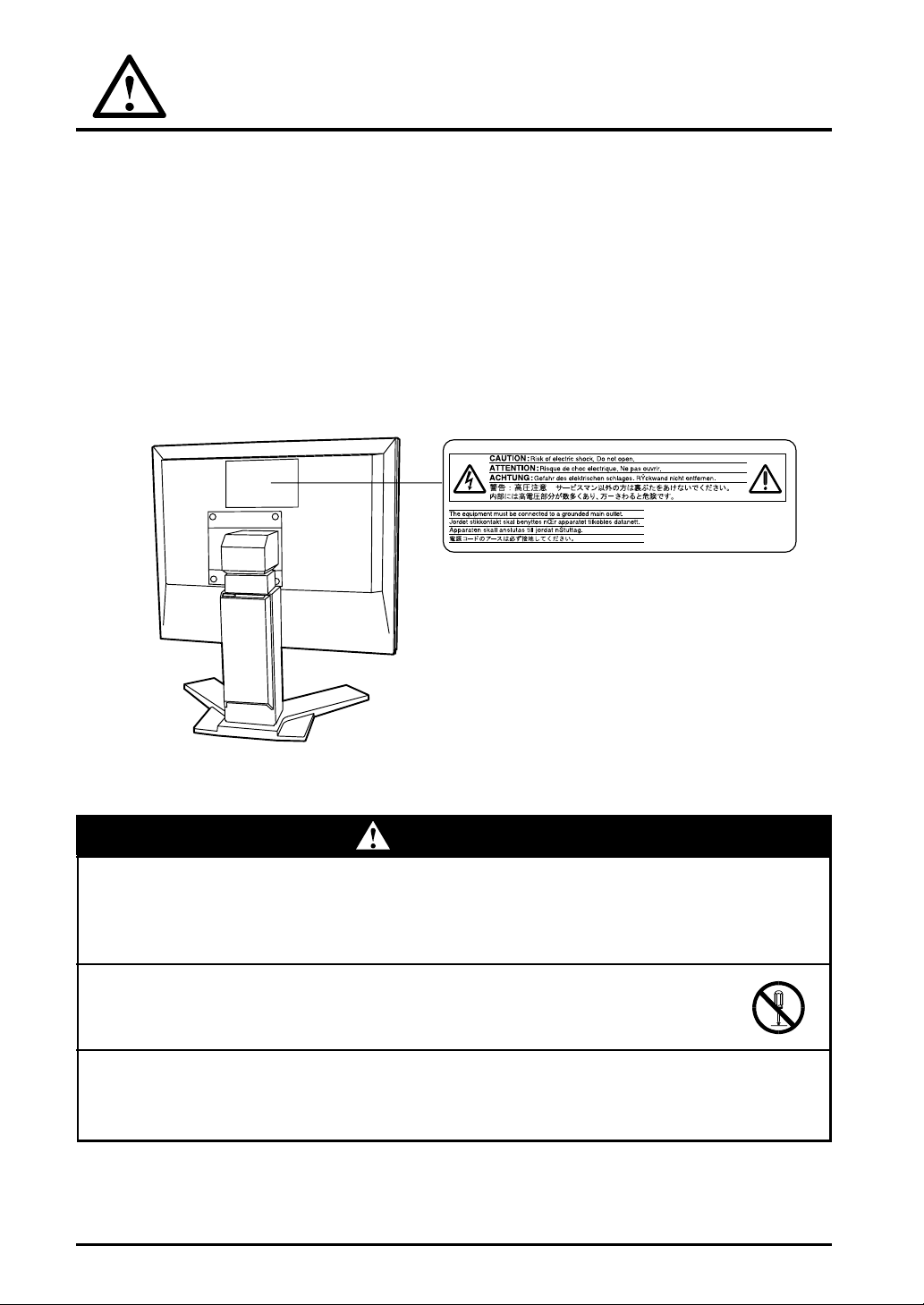
PRECAUTIONS
IMPORTANT
• This Product has been adjusted specifically for use in the region to which it was
originally shipped. If operated outside the region to which it was originally shipped,
the product may not perform as stated in the specifications.
• To ensure personal safety and proper maintenance. Please read this section and the
caution statements on the unit (refer to the figure below).
[Location of the Caution Statements]
WARNUNG
• If the unit begins to emit smoke, smells like something is burning, or
makes strange noises, disconnect all power connections immediately
and contact your dealer for advice.
Attempting to use a malfunctioning unit can be dangerous.
• Do not dismantle the cabinet or modify the unit
Dismantling the cabinet or modifying the unit may result in electric shock or
burn.
• Refer all servicing to qualified service personnel.
Do not attempt to service this product yourself as opening or removing covers
may expose you to dangerous voltage or other hazards.
WARNING
4 PRECAUTIONS
Page 5
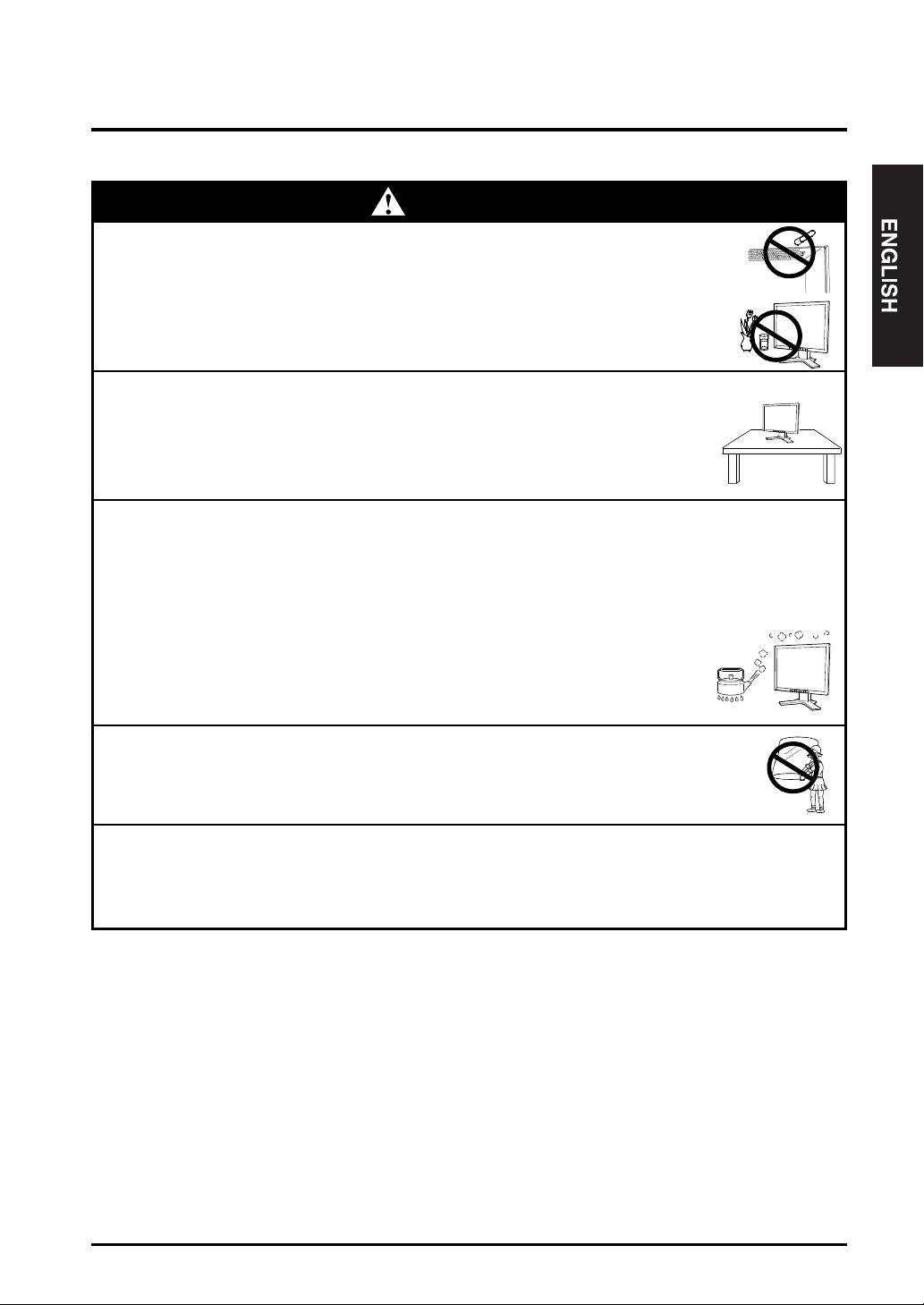
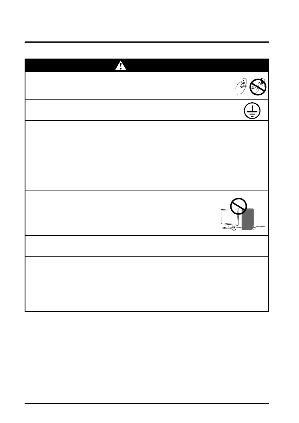
WARNING
• Keep small objects or liquids away from the unit.
Small objects accidentally falling through the ventilation slots into the cabinet
or spillange into the cabinet may result in fire, electric shock, or equipment
damage. If an object or liquid falls/spills into the cabinet, unplug the unit
immediately. Have the unit checked by a qualified service engineer before
using it again.
• Place the unit on a strong, stable surface
A unit placed on an inadequate surface may fall, resulting in injury or
equipment damage. If the unit falls, disconnect the power immediately and
have the unit checked by a qualified service engineer before using it again.
Using a unit after it has been dropped may result in fire or electric shock.
• Set the unit in an appropriate location.
Not doing so may cause damage and could result in fire or electric shock.
* Do not place in outdoors.
* Do not place in the transportation system (ship, aircraft, trains,
automobiles, etc.)
* Do not install in a dusty or humid environment.
* Do not place in a location where steam can have direct contact with the
screen.
* Do not place near heat generating devices or humidifier.
OK
• To avoid danger of suffocation, keep the plastic packing bags away from
babies and children.
• Use the enclosed power cord and connect to the standard power outlet
of your country. Be sure to remain within the rated voltage of the power
cord.
Not doing so may cause in fire or electric shock.
PRECAUTIONS 5
Page 6
WARNING
• To disconnect the power cord, grasp the plug firmly and pull.
Never tug on the cord, doing so may cause damage and could result in fire or
electric shock.
• The equipment must be connected to a grounded main outlet.
Not doing so may cause in fire or electric shock.
• Use the correct voltage.
* The unit is designed for use with a specific voltage only. Connection to a
another voltage than specified in this User’s Manuall may cause fire,
electric shock, or other damage.
* Do not overload your power circuit, as this may result in fire or electric
shock.
* For proper connections of the power cord, be certain to plug the power
cord to the provided unit connector and directly to a wall outlet. Not doing
so may result in fire or electric shock.
• Handle the power cord with care.
* Do not place the cord underneath the unit or other heavy objects.
* Do not pull on or tie the cord.
If the power cord becoomes damaged, stop using it. Use of a damaged
cord may result in fire or electric shock.
OK
• Never touch the plug and power cord if it begins to thunder.
Touching them may result in electric shock.
• When attaching an arm stand, please refer to the user’s manual of the
arm stand and install the unit securely with the enclosedd screws.
TNot doing so may caause the unit to come unattached, which may result in
injury or equipment damage. When the unit is dropped, please ask your
dealer for advise. Do not continue using a damaged unit. Using a damaged
unit may result in fire or electric shock. When reattaching the tilt stand, please
use the same screws and tighten them securely.
6 PRECAUTIONS
Page 7
WARNING
• Do not touch a damaged LCD panel directly with bare hands.
The liquid crystal which leaks from the panel is poisonous if it enters the
eyes or mouth. If any part of the skin or body comes in direct contact with
the panel, please wash throughly. If some physical symptoms result,
please consult your doctor.
• Follow local regulation or laws for safe disposal.
The backlight of the LCD panel contains mercury.
CAUTION
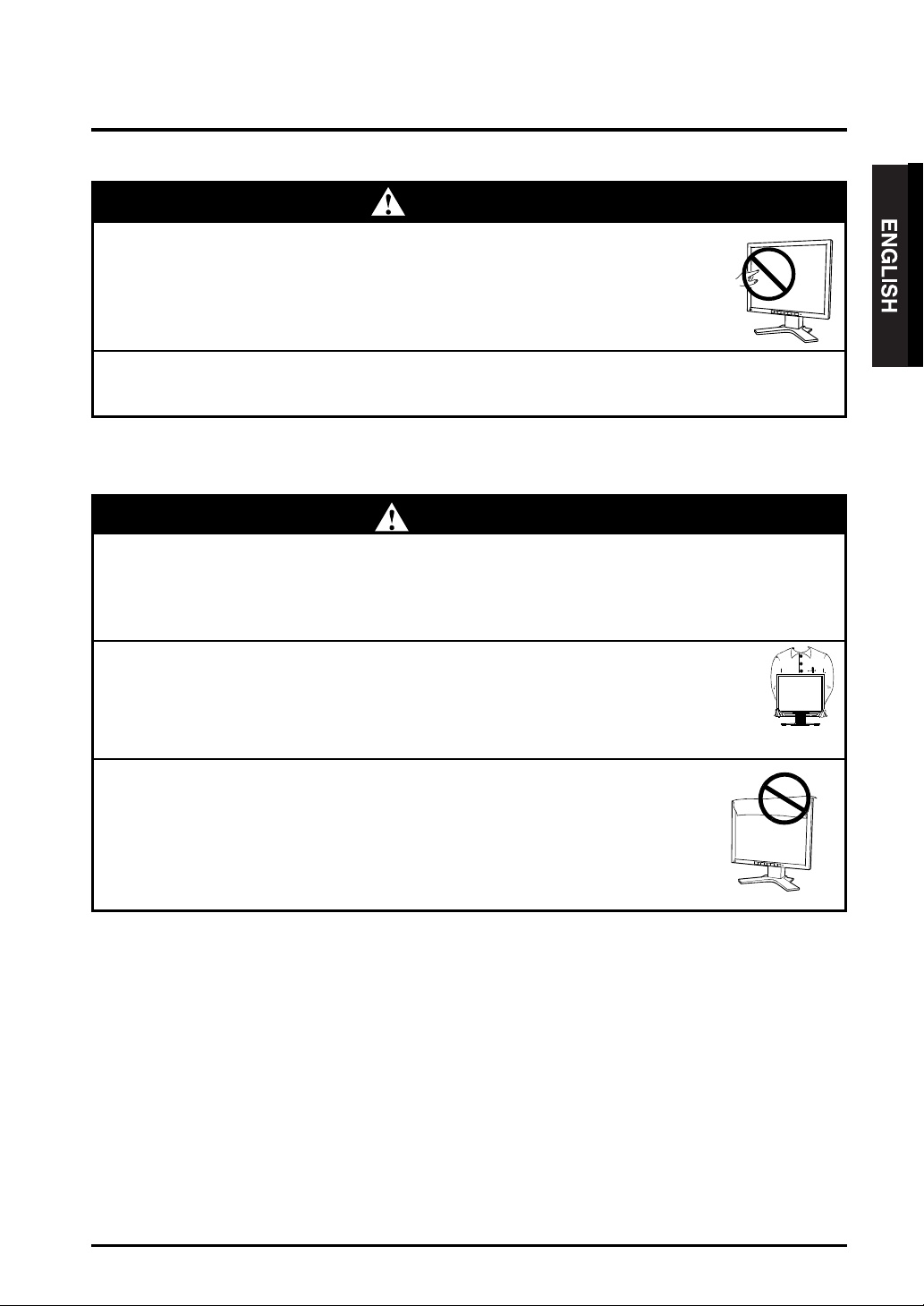
• Handle with care when carrying the unit.
Disconnect the power cord, cables when moving the unit. Moving the unit
with the cord attached is dangerous. It may result in injury or equipment
damage.
• When handling the unit, grip the bottom of the unit firmly with both
hands ensuring the panel faceees outward before lifting.
Dropping the unit may result in injury or equipment damage.
OK
• Do not block the ventilation slots on the cabinet.
* Do not place books or any other papers on the ventilation slots.
* Do not install the unit in a closed space.
* Do not use the unit laying down or upside down.
Using the unit in these ways blocks the ventilation slots and prevents proper
airflow, leading to fire or other damage.
PRECAUTIONS 7
Page 8
CAUTION
• Do not touch the plug with wet hands.
Touching the plug with wet hands is dangerous and can cause electrical
shock.
• Use an easily accessible power outlet.
This will ensure that you can disconnect the power quickly in case of a
problem.
• Periodically clean the area arounf the plug.
Buildup of dust, water, or oil on the plug may result in fire.
• Unplug the unit before cleaning it.
Cleaning the unit while it is plugged into a power outlet may result in electric
shock.
• If you plan to leave the unit unused for an extended period, disconnect
the power cord from the wall socket after turning of the power switch for
the safety and the power conservation.
8 PRECAUTIONS
Page 9
LCD Panel
• The screen may have defective pixels. These pixels may appear as
slightly light or dark area on the screen. This is due to th characteristics
of the panel itself, and not the product.
• The backlight of the LCD panel has a fixed life span.
When the screen becomes dark or begins to flicker, please contact your
dealer.
• Do not press on the panel or edge of the frame strongly, as this will result
in damage to the screen. There wil be prints left on the screen if the
pressed image is dark or black. If pressure is repeatedly applied to the
screen, it may deteriorate or damage your LCD panel. Leave the screen
white to decrease the prints.
• Do not scratch or press on the panel with any sharp objects, such as a
pencil or pen as this may result in damage to the panel. Do not attempt to
brush with tissues as this may scratch the LCD panel.
PRECAUTIONS 9
Page 10

1. INTRODUCTION
Thank you very much for choosing an EIZO Color LCD Monitor.
1-1. Features
• DVI
• Two images can be displayed at the same time by dual input support
• 2048 x 1536 resolutioon (Actual video resolutioon: 1024 x 1536)
• The height adjustable stand incorporated
• Ultra slim bezel incorporated
• The portrait/Landscape display capability
• Power saving function (DVI-DMPM
• The FA-2090 supports dual video input. The video input setting and the power
• The power saving function is always “ON” during operation.
p.24)
Digital input (TMDS
Horizontal scanning frequency of 92.86 - 96.72 kHz
Vertical scanning frequency of 60 Hz
saving function depend on settings by graphic boards.
p.24)
1-2. Package Contents
) compliance (DVI-I x 2)
p.24)
)
Please contact your local dealer for assistance if any of the listed items are missing or
damaged.
• LCD Monitor • Power Cord
• Signal Cable (FD-C04) ... x2 • User’s Manual
• Warranty Registration Card
• Please retain the packing materials for future transference.
10 1. INTRODUCTION
Page 11

1-3. Controls, Connectors & Functions
Controls & Connectors
[Front]
(2)
(1) Main Power Switch
(2) Contrast Adjustment Button (+, -)
(3) Brightness Adjustment Button (+, -)
(4) Power Button
(5) Power Indicator
Indicated Color Power-on status
Green Power is on/ Main power is off
Yellow Power save mode
Slowly flashing Yellow Power is off (Main power is on)
(3) (4)(1)
(5)
1. INTRODUCTION 11
Page 12

[Rear]
(6) (7) (8) (10)(9)
(6) Height Adjustable Stand (Detachable)
(7) DVI-I Input Connector (Signal 1)
(8) DVI-I Input Connector (Signal 2)
(9) Power Connector
(10) Security Lock Slot
*1
The LCD monitor can be used with an optional arm stand by removing the stand (see
page 19)
*2
Allows for connection of a security cable. This lock supports Kensington’s
MicroSaver security system. For further information, please consult:
Kensington Technology Group 2855 Campus Drive, San Mateo, CA 94403 USA
800-850-4242, x3348
Intl: 650-572-2700, x3348 /Fax: 650-572-9675
http://www.kensington.com
12 1. INTRODUCTION
*1
*2
Page 13

Functions
The LCD monitor offers two (2) functions for screen adjustment and a useful
function for daily use.
Brightness Adjustment
Adjust screen brightness level by each (+) or (-) key of Brightness Adjustment
Button. To finish the adjustment will save the data automatically.
Contrast Adjustment
Adjust screen contrast level by each (+) or (-) key of Contrast Adjustment Button.
To finish the adjustment will save the data automatically.
Adjustment Lock
Use the function to prevent any accidental changes of screen adjustment.
• To lock
Turn off the monitor’s Main Power Switch while image is
diaplayed on the screen. Press on the (-) key of the Contrast
Adjustment Button while switching on the monitor’s Main
Power Switch.
• To unlock
Turn off the monitor’s Main Power Switch while image is
diaplayed on the screen. Press on the (-) key of the Contrast
Adjustment Button one again while switching on the
monitor’s Main Power Switch.
1. INTRODUCTION 13
Page 14

2.
CONNECTING UP
2-1. Before connecting
Supported Resolution
The FA-2090 can be used to connect with the special graphics board which has a
capability of dual video signal output.
This monitor supports the following mode and input video signal.
Supported Resolution
• Display Resolution 2048 dots x 1536 lines
• Input Video Resolution 1024 dots x 1536 lines
Input Video Signal
• Horizontal Scanning Frequency fH: 92.86 - 96.72 kHz
• Vertical Scanning Frequency fV: 60 Hz
• Dot Clock 120 - 132 MHz
14 2. CONNECTING UP
Page 15

2-2. Connecting the signal cable
The FA-2090 has two display area on a display panel. To display both area, it is
required to plug signal cables to each Signal 1 or Signal 2 connector.
Signal 1Signal 2
Default setting (Landscape) Portrait Setting (Refer to p. 18)
• Be sure that the power switches of both the PC and the monitor are OFF.
1. Plug the signal cables into each DVI-I connector at the rear of the
monitor and the other end of the cable into the video connector on
the PC.
Signal 1
Signal 2
After attaching the connectors, secure the connection with the screw-in fasteners.
[DVI-I Input (Signal 1 / Signal 2)]
Connecteur
DVI-I à l’arrière
To Signal 1 Connector
FD-C04 (enclosed)
To Signal 2 Connector
FD-C04 (enclosed)
Video Output Connector
DVI
Digital graphics board
Video Output Connector
DVI
Digital graphics board
2. CONNECTING UP 15
Page 16

• Check that both Signal 1 and Signal 2 connector is securely connected.
If not, the images cannot be displayed.
2. Plug the power cord into the power connector on the rear of the
monitor
3. Lead the power cord and signal cables into the cable holder at the
rear of the monitor.
• When housing the cables into the cable holder, lead them to the cable
entrance side and pinch the projection to open the cable entrance.
• The cables are recommended to lead with slight sag for the smooth motion of
the stand.
Cable Holder
16 2. CONNECTING UP
Projection
Cable Entrance
Page 17

4. Plug the other end of the power cord into a power outlet.
WARNING
• Use the enclosed power cord and connect to the standard
power outlet of your country. Be sure to remain within the
rated voltage of the power cord.
Not doing so may cause in fire or electric shock.
• The equipment must be connected to a grounded main
outlet.
Not doing so may result in an electric shock.
5. Turn on the monitor’s power and then switch on the PC’s power.
Whenever finished, turn off the PC and the monitor.
• If any image is NOT displayed, refer to “TROUBLESHOOTING” (p.21)
• The monitor automatically enters the power saving mode whenever the graphics
board goes to DVI-DMPM power save mode. To complete power saving, turn off
the Main Power Switch and disconnect the monitor from the power supply while you
don’t use the monitor.
Suggestions for Maximizing Comfort
• Adjust brightness of the screen depending on the brightness of your environment.
Too dark or too bright of a screen can cause eye strain.
• Be sure to take adequate rests. A10-minute rest period each hour is suggested.
2. CONNECTING UP 17
Page 18

2-3. Portrait monitor setting
This monitor can be rotated counterclockwise and used as a portrait monitor.
• Be sure that the power switche of the monitor is OFF.
• Hold upper-left and bottom-right corner with both hands, then gently rotate
the display panel.
• Turn on the monitor after confirming that the display panel is perfectly rotated
by 90 degrees.
• Refer to the User’s Manual of graphics board about the software settings when
using portrait monitor.
18 2. CONNECTING UP
Page 19

3. ATTACHING AN ARM STAND
The LCD monitor can be used with an arm stand by removing the tilt stand and
attaching the arm stand to the LCD monitor.
• Use an arm stand that satisfies the followings.
• When using the LCD monitor with an arm stand, the
arm stand must be VESA approved :
* Use an arm stand with a 100 mm x 100 mm hole
spacing on the arm mounting pad.
* Use an arm stand that is able to support an
object weighing 6.5 kg.
• TÜV/GS approved arm stand.
• Use an arm stand with sufficient stability
(mechanical firmness) to support the weight of the
monitor.
• Use an arm stand remaining that position where it is
manually moved.
• Use an arm stand with the ability to tilt the monitor
forward and backward.
• Please connect cables after attaching an arm stand.
Setup Procedure
1. Lay the LCD monitor down. Do not scratch the panel.
M4 (4 points)
100 mm
100 mm
2. Remove the stand by loosening the screws. (4 pcs of M4 x 10)
3. ATTACHING AN ARM STAND 19
Page 20

3. Attach an arm stand to the LCD monitor securely.
WARNING
• When attaching an arm stand, please refer to the user’s
manual of the arm stand and install the unit securely with the
enclosed screws.
Not doing so may cause the unit to come unattached, which may
result in injury or equipment damage. When the unit is dropped,
please ask your dealer for advice. Do not continue using a
damaged unit. Using a damaged unit may result in fire or electric
shock. When reattaching the tilt stand, please use the same
screws and tighten them securely.
M4 Mounting Screws :
M4 x 10 (mm)
20 3. ATTACHING AN ARM STAND
Arm-stand
Page 21

4. TROUBLESHOOTING
If a problem persists even after applying the suggested remedies, contact your dealer.
Problems Points to check with possible solutions
1. No picture
ENGLISH
• Indicator status: Off
• Indicator status: Green
• Indicator status: Yellow
• Indicator status: Slowly
flashing Yellow
2. The screen is too bright or
too dark.
3. After image
4. The screen has defectiv
pixels (e.g. slightly light or
dark).
p.24)
s appear.
Check that the power cord is correctly connected.
If the problem persists, turn off the monitor power for a
few minutes, then turn it back on and try again.
Check the “Contrast and Brightness” settings. Minimum
settings will cause screen to be blank.
Try pressing a key on the keyboard, or clicking the
mouse.
Check that both signal cables are securely connected.
Try pressing the power button.
Adjust the “contrast and brightness”.
(The backlight of the LCD monitor has a fixed life span.
When the screen becomes dark or begins to flicker, please
contact your dealer.)
When the screen image is changed after displaying the
same image for a long period, an afterimage may appear.
This is due to the characteristics of the panel itself, and
not the LCD product.
5. Fingerprints remain on the
screen.
6. The right and left image is
displayed contrary. (Or
upper and lower image is
displayed upside down.)
Leaving the screen black may solve the problem.
Check whether the signal cable is plugged to correct side
of DVI-I input connector.
4. TROUBLESHOOTING 21
Page 22

5. CLEANING
Periodic cleaning is recommended to keep the monitor looking new and to prolong its
operation lifetime.
• Never use thinner, benzene, alcohol (ethanol, methanol, or
isopropyl alcohol), abrasive cleaners, or other strong solvents, as
these may cause damage to the cabinet or LCD panel.
Cabinet
To remove stains, wipe the cabinet with a soft, lightly moistened cloth using a mild
detergent. Do not spray wax or cleaner directly onto the cabinet.
LCD Panel
The LCD surface can be cleaned with a soft cloth, such as cotton or lens paper.
If necessary, stubborn stains can be removed by moisterning part of a cloth with water
to enhance its cleaning power.
22 5. CLEANING
Page 23

6. SPECIFICATIONS
FA-2090
LCD Panel 53 cm (20.8 inch), TFT color LCD panel
Viewing Angle: Horizontal : 170 º, Vertical : 170º
(at Contrast Ratio >10)
Dot Pitch 0.207 mm
Scan Frequency Horizontal: 92.86 kHz - 96.72 kHz (Automatic)
Vertical : 60 Hz
Resolution 2048 dots x 1536 lines
Dot Clock (Max.) 132 MHz
Display Colors 16 million colors (Max.)
Display Area 423.9 mm (H) x 318.0 mm (V) (16.7” (H) 12.5” (V))
(Viewable image size: 529 mm (20.8”))
Power Supply 100-120/200-240 VAC±10%, 50/60 Hz, 0.8 A/0.4 A
Power Consumption Normal/Max.: 70 W / 80 W
Power Saving Mode: less than 5 W
Input Connector DVI-I x 2
Input Signal Digital: TMDS (Single Link)
Dimensions
(Landscape setting) 474 mm (W) x 466.5 mm (H: minimum) x 208.5 mm
(D) (18.7” (W) x 16.7” (H): minimum) x 8.2” (D))
(Portrait setting) 368 mm (W) x 519.5 mm (H) x 208.5 mm (D)
(14.4” (W) x 20.5” (H) x 8.2”(D))
(Without stand) 474 mm (W) x 368 mm (H) x 83.5 mm (D)
(18.7” (W) x 14.4” (H) x 3.3”(D))
Adjustable Height 72 mm
Weight (With stand) 9.5 kg (20.9 lbs.)
(Without stand) 6.3 kg (14.3 lbs.)
Temperature Operating :0°C to 35°C (32°F to 95°F)
Storage:-20°C to 60°C (-4°F to 140°F)
Humidity 30 % to 80 % R.H. Non-condensing
6. SPECIFICATIONS 23
Page 24

7. GLOSSARY
Afterimage
The After image is particular to LCD monitors when the monitor screen is left on
for a long period without use. The “After image” can be removed gradually by
changing the displayed image.
DVI
(Digital Visual Interface)
A digital flat panel interface. DVI can transmit digital data from the PC directly
without loss with the signal transition method “TMDS”. There are two kinds of
DVI connectors. One is DVI-D connector for digital signal input only. The other is
DVI-I connector for both digital and analog signal inputs.
The monitor complies with DVI-D, though it is equipped DVI-I connector(s).
DVI-DMPM
(DVI Digital Monitor Power Management)
The Power management system for the digital interface. The “Monitor ON”
status (operation mode) and the “Active Off” status (power-saving mode) are
indispensable for the DVI-DMPM as the monitor’s power mode.
TMDS
(Transition Minimized Differential Signaling)
A signal transition method for the digital interface.
24 7. GLOSSARY
Page 25

8. INDEX
A
Adjustment Lock ------------------------ 13
Afterimage ------------------------------ 24
ATTACHING AN ARM STAND------ 19
B
Brightness Adjustment ----------------- 11
Brightnes Adjustment Button --------- 13
C
CLEANING ------------------------------- 22
CONNECTING UP --------------------- 14
Contrast Adjustment ------------------- 11
Contrast Adjustment Button -------- 11
Controls & Connectors ---------------- 11
D
Dimensions --------------------------------- i
DVI ---------------------------------------- 24
DVI-DMPM ------------------------------ 24
F
Features ---------------------------------- 10
G
GLOSSARY ----------------------------- 24
I
INTRODUCTION ---------------------- 10
L
LCD Panel--------------------------------- 9
M
Main Power Switch -------------------- 11
P
Package Contents---------------------- 10
Portrait monitor setting ---------------- 18
Power Button ---------------------------- 11
Power Consumption ------------------- 23
Power Indicator ------------------------- 11
PRECAUTIONS--------------------------- 4
S
SAFETY SYMBOLS --------------------- 2
Security Lock Slot -------------------- 12
SPECIFICATIONS -------------------- 23
Supported Resolution --------------- 14
T
TMDS------------------------------------- 24
TROUBLESHOOTING --------------- 21
8. INDEX 25
Page 26

Dimensions
Abmessungen
Dimensions
FRONT VIEW
VORDERANSICHT
VUE DE FACE
Pin Assignment
Pin-Belegung
Affectation des Broches
* DVI-D Connector
SIDE VIEW
SEITENANSICHT
VUE DE COTE
Pin
No.
1 TMDS Data2- 11 TMDS Data1/3 21
Shield
2 TMDS Data2+ 12 22 TMDS Clock
Shield
3 TMDS Data2/4 13 23 TMDS Clock+
Shield
4 14 +5V Power 24 TMDS Clock-
5 15 Ground C1
(Return for +5V,
H sync and V sync)
6 16 Hot plug detect C2
7 17 TMDS Data0- C3
9 TMDS Data1- 19 TMDS Data/5 C5 Analog Ground
Shield (Analog R, G & B
Return
10 TMDS Data1+ 20
Signal
8 18 TMDS Data0+ C4
TOP VIEW
DRAUFSICHT
VUE D’EN HAUT
Pin
No.
Signal
Pin
No.
Signal
APPENDIX
Page 27

For U.S.A, Canada, etc. (rated 100-120 Vac) Only
WARNING
This equipment has been tested and found to comply with the limits for a Class A digital
device, pursuant to Part 15 of the FCC Rules. These limits are designed to provide
reasonable protection against harmful interference when the equipment is operated in a
commercial environment. This equipment generates, users, and can radiate radio
frequency energy and if not installed and used in accordance with the instruction
manual, may cause harmful interference to radio communications. Operation of this
equipment in a residential area is likely to cause harmful interference in which case the
user will be required to correct the interference at his own expense.
Changes or modifications not expressly approved by the party responsible for
compliance could void the user’s authority to operate the equipment.
Note
Use the attached specified cable with this unit below so as to keep interference within the
limit of a Class A computing device.
• AC Cord
Canadian Notice
This Class A digital apparatus complies with Canadian ICES-003.
Cet appareil numérique de le classe A est comforme à la norme NMB-003 du Canada.
Warni ng
This is a Class A product. In a domestic environment this product may cause radio
interference in which case the user may be required to take adequate measures.
Page 28

Hinweis zur Ergonomie:
Dieser Monitor erfüllt die Anforderungen an die Ergonomie nach EK-1-ITB-2000 mit dem
videosignal, 2048 Punkte x 1536 Zeilen, Digital Eingang und mindestens 60,0 Hz
Bildwiederholfrequentz, (non-interlaced).
Weiterhin wird aus ergonomischen Gründen empfohlen, die Grundfarbe Blau nicht auf
dunklem Untergrund zu verwenden (schlechte Erkennbarkeit, Augenbelastung bei zu
geringem Zeichenkontrast.)
Recycle Auskunft
Die Rücknahme dieses Produktes nach Nutzungsende übernimmt EIZO in Deutschland
zusammen mit dem Partner von Roll MBB Recycling GmbH.
Dort werden die Geräte in ihre Bestandteile zerlegt, die dann der Wiederverwertung
zugeführt werden.
Um einen Abholtermin zu vereinbaren und die aktuellen Kosten zu erfahren, benutzen Sie
bitte folgende Rufnummer: 02153-73 35 00. Weitere Informationen finden Sie auch unter
der Internet-Adresse: www.eizo.de.
 Loading...