

EIT UV Power Puck II, UviCure Plus II User Manual
EIT®
UV Power Puck® II & UviCure® Plus II
User’s Guide
Electronic Instrumentation and Technology (EIT) LLC
309 Kelly’s Ford Plaza SE
Leesburg VA 20175 USA
Phone: 703-478-0700
Email: uv@eit.com
Web: www.eit.com
EIT Part Number P/N IM-0111 Rev A Issued April 2019

Table of Contents
Introduction ............................................................................................................................................................................. 1
The Process Values ................................................................................................................................................................. 1
Operation and Features ........................................................................................................................................................... 2
Operating the Radiometer ....................................................................................................................................................... 4
Data Collection Techniques .................................................................................................................................................... 7
Diagnostics & Error Messages ............................................................................................................................................. 13
Low Battery Indicator ....................................................................................................................................................... 13
Over-Temperature State .................................................................................................................................................... 13
Over Range State ............................................................................................................................................................... 13
Other Error Codes ............................................................................................................................................................. 13
Maintenance – Cleaning and Calibration ............................................................................................................................. 14
Cleaning-Display ............................................................................................................................................................... 14
Calibration ......................................................................................................................................................................... 14
EIT UV Instrument New Product and Calibration/Repair Warranty ................................................................................... 16
Appendix A: Optics Cleaning ............................................................................................................................................... 17
Appendix B: Specifications .................................................................................................................................................. 19
Appendix C: Instrument Types and Software ....................................................................................................................... 20
Appendix D: Regulatory Statements .................................................................................................................................... 22
EIT Part Number P/N IM-0111 Rev A Issued April 2019
Introduction
The EIT UV Power Puck® II and UviCure® Plus II are used globally for industrial UV measurement and process
control. With user selectable sample rates, reference modes, UV irradiance profile graphs and other features, these
instruments can be used for fast or slow conveyor lines and the measurements are compatible with other EIT products.
The instruments are simple to use with one-button operation.
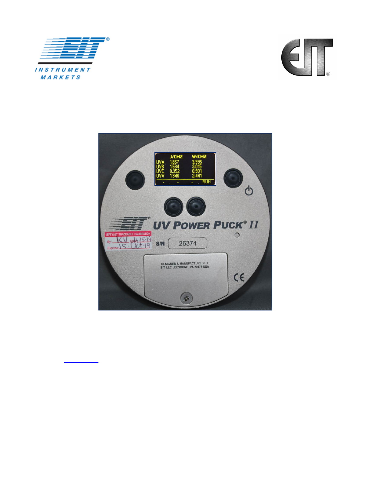
The UV Power Puck II and UviCure Plus II are self-contained, electro-optic radiometers that measure and display total
UV energy and UV irradiance in a UV curing system. The UV Power Puck II and UviCure Plus II combine compact size
and robust design to withstand the extremes of UV curing environments while providing accurate measurement.
The carefully designed optical sensing systems only measure wavelengths that are relevant to the UV process. The
output of the sensing system is converted to digital form and displayed on an easy-to-read OLED display.
The UV Power Puck II simultaneously measures four different ranges of ultraviolet wavelengths with one pass through
the UV process. The UV Power Puck II default wavelengths are UVA (320-390nm), UVB (280-320nm), UVC (250260nm) and UVV (395-445nm). The UviCure Plus II includes a choice of one of the EIT wavelength bands.
The instrument reading includes total energy and peak irradiance of all four transmission bands for the UV Power Puck
II and one band for the UviCure Plus II.
The EIT UV Power Puck II and UviCure Plus II are designed and manufactured in the USA.
The Process Values
Reaching the energy density and irradiance values specified by your process along with the proper bulb type is
necessary for achieving consistent acceptable UV cure.
The two process values read by the UV Power Puck II and UviCure Plus II are peak irradiance and total energy
density.
The irradiance reading is the peak intensity measured during the exposure run. The radiometers measure and display
irradiance in Watts, milliWatts or microWatts per square centimeter (W/cm2, mW/cm2, µW/cm2). If the unit is used to
measure multiple lamps, the peak irradiance value will correspond to the most intense lamp.
Total energy density (sometimes called dose) is a factor of the irradiance over time. The instruments derive this value
from the irradiance values during the exposure run and the length of time of the run. Total energy is measured in
Joules, milliJoules or microJoules per square centimeter (J/cm2, mJ/cm2, µW/cm2). If the unit is used to measure
multiple lamps, the total energy density value will be the sum of all lamps.
Ultraviolet Radiation
This product is not a source of UV radiation (energy/light).
It is used in an environment where UV is present and protective
measures (eye/skin) against UV radiation should be followed.
Refer to the UV source's documentation for information.
EIT Part Number P/N IM-0111 Rev A Issued April 2019
Page 1
Unit Serial Number
See below
Alarm
Calibration Label
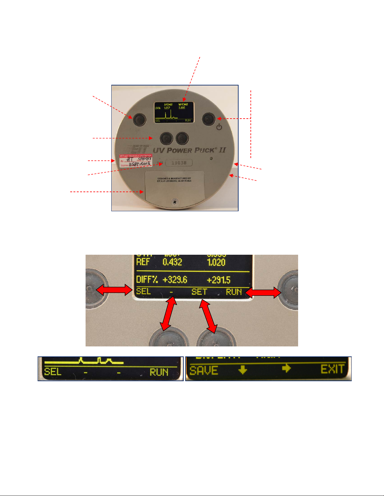
Operation and Features
Setup Mode Button
Soft Button Operation
Buttons perform the
function indicated on the
display bottom line.
Battery Door
Button Operation
The four buttons on the face of the instrument correspond to the adjacent function shown on the display. The functions will
change automatically based on the instrument mode. Examples of different functions are shown below.
Display
On / Off Button
Depress and Hold until
screen is illuminated.
Run / Exit Run Button
Press to enter Run
Mode.
Press to Exit Run Mode.
USB Port
Used for calibration and
data communication in
Profiler enabled
instruments
Examples of some of the different functions that will be shown under the instrument display
EIT Part Number P/N IM-0111 Rev A Issued April 2019
Page 2
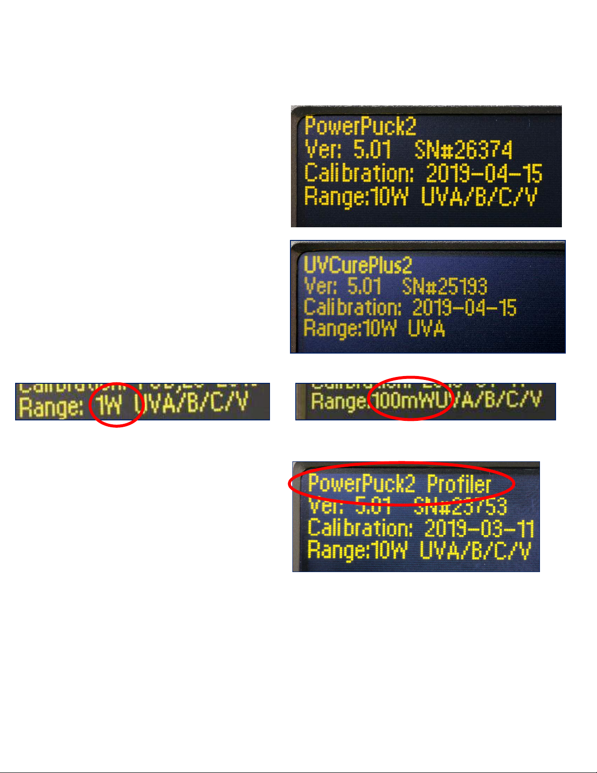
Unit Type
The first screen displayed momentarily when the unit is turned on will indicate the unit type and dynamic range. Pushing
and holding the On/Off Button will keep the display on this screen.
Unit Type (Standard Power Puck II)
Internal Firmware Version & Serial Number
Last Calibration Date
Dynamic Range (10 Watts) and UV bands
(UVA, UVB, UVC & UVV)
Unit Type (UviCure Plus II)
Internal Firmware Version & Serial Number
Last Calibration Date
Dynamic Range (10 Watts) and UV band (UVA)
Above Left: Unit with Dynamic Range of 1 Watt
Above Right: Unit with Dynamic Range of 100
milliWatts
Right: Power Puck II Profiler on Startup screen.
See Appendix C for more information on the
Profiler Versions of our instruments
EIT Part Number P/N IM-0111 Rev A Issued April 2019
Page 3

Operating the Radiometer
Turning “ON” the Radiometer: Press and Hold the ON / OFF button until the display illuminates. The display will
briefly display the Radiometer Model Name, Serial Number, Software Version, Calibration Date, Range, and
Wavelength Bands installed. (See previous page) The display will then enter the default mode and display the data
from the last run before the unit was turned off.
Turning “OFF” the Radiometer: Press and Hold the ON / OFF button. A tone will sound. When tone stops, release
the button. The unit turns off.
Entering the “RUN” MODE: A short press of the “RUN” button clears the memory and puts the unit in the “RUN”
mode. The display shows “RUNNING” after shortly displaying the internal temperature of the unit. Confirm that the
unit displays “RUNNING” before initiating a reading.
Place the radiometer on the belt or object with the optic window looking toward the UV source. The display and buttons
will be facing away from the UV source. When the radiometer exits the curing chamber, the display will still be flashing
“RUNNING”.
CAUTION: Exposing the display to high UV radiation will damage the display.
Exiting the “RUN” MODE: A short press of the “STOP” button (Soft button display bar indicates “STOP” next to the
“ON / OFF” button) will exit the “RUN” mode and will return to the same default mode prior to making the exposure
run, but will display the new value.
EIT Part Number P/N IM-0111 Rev A Issued April 2019
Page 4

Setup & Default Modes
To enter the Setup Mode, use the soft button to the left of the display, Press and hold for 0.5 second, then release.
The Setup screen will display the current settings. Default modes are designated using an *asterisk.
The setup screen below shows all possible choices for each mode.
To change selections, use the down and right arrow buttons located under the arrows to scroll in the
indicated direction. To change the default selection, first select the line, then the setting on each line. Press the
SAVE button to save the setting as the new default. An *asterisk will appear next to the setting.
When changes are completed, press the EXIT button to return to the default mode.
SETUP
*MODE: *ALL CHANNEL REFERENCE GRAPH
SMOOTH: *OFF ON
UNITS: *J/W mJ/mW uJ/ uW
DISPLAYS: LOW *MEDIUM HIGH
SAVE EXIT
UV Power Puck II Setup Screen
SETUP
*MODE: *GRAPH REFERENCE TOGGLE
SMOOTH: *OFF ON
UNITS: *J/W mJ/mW uJ/ uW
DISPLAYS: LOW *MEDIUM HIGH
SAVE EXIT
UviCure Plus II Setup Screen
EIT Part Number P/N IM-0111 Rev A Issued April 2019
Page 5
Explanation of Settings:
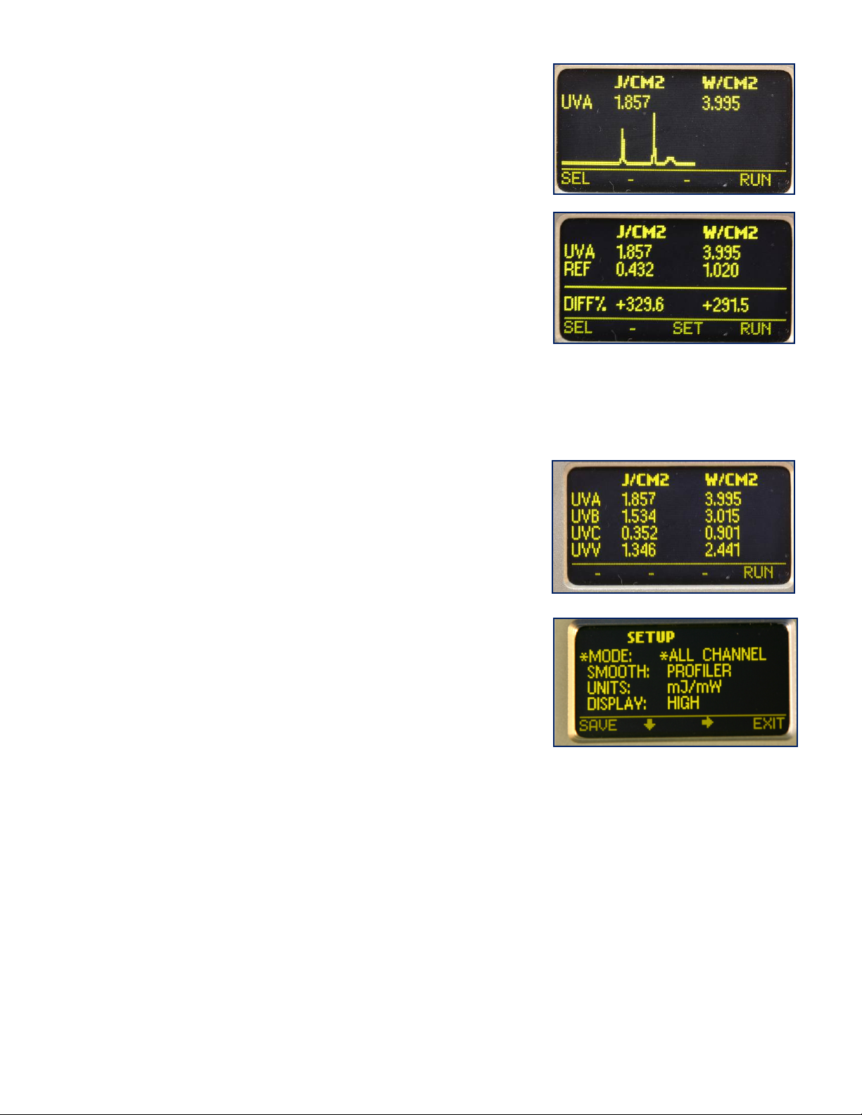
MODE:
GRAPH – Illustrates the irradiance profile for the UV source(s). UV
Data is stored and displayed as a graph of time (X axis) vs.
intensity (Y axis) for each UV lamp source.
REFERENCE – Make a run, data will appear next to the UV band.
CAUTION: Be sure you want to overwrite the current data on
the REF line before pressing SAVE. Press SAVE, data is
transferred to the REF line. The data will remain until it is
overwritten. The difference or change between the current run
data and the reference data is displayed as a percentage change
on the DIFF% line.
TOGGLE (UviCure Plus II Only) – Pressing the SEL button, the user can “toggle” between the GRAPH and
REFERENCE modes shown above.
ALL CHANNEL (UV Power Puck II Only) – displays Joules and
Watts for each of the four (4) UV bands (UVA, UVB, UVC, UVV)
SMOOTH: There is a detailed discussion of SMOOTH in the
Instrument Sample Rate section of the User’s Guide
UNITS: J/W, mJ/mW , µJ/ µW – Select the unit values
DISPLAYS: LOW, MEDIUM, HIGH – Select the display intensity
SAVE EXIT – Soft Button Indicators
EIT Part Number P/N IM-0111 Rev A Issued April 2019
Page 6
 Loading...