

Eisys iMove-C, iMove-F Assembly Manual
eisysDESKING
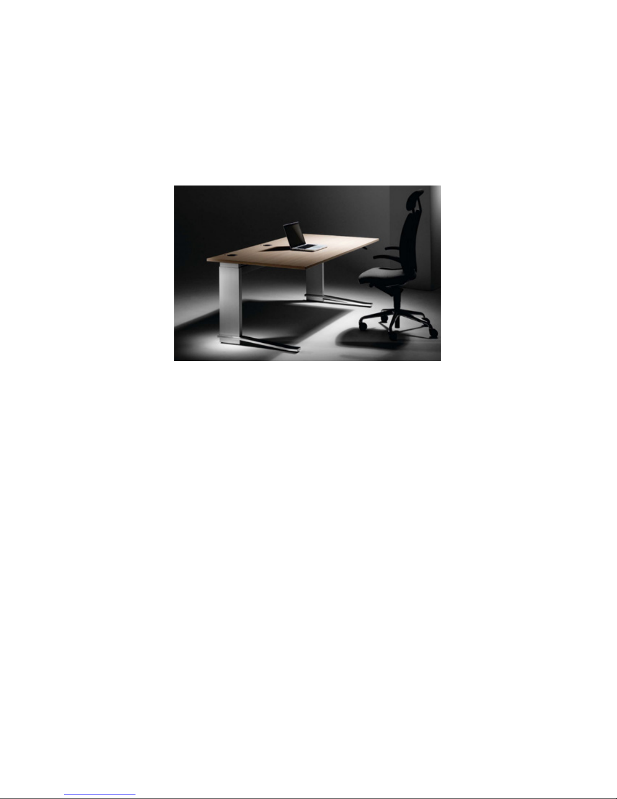
iMove-C Assembly Manual
(Pneumatic Version-H1/H2)
eisys, inc. 112 28th Street South • Birmingham, Alabama 35233 • 205.941.1942 • www.eisys-inc.com

eisysDESKING
Table of Contents
2
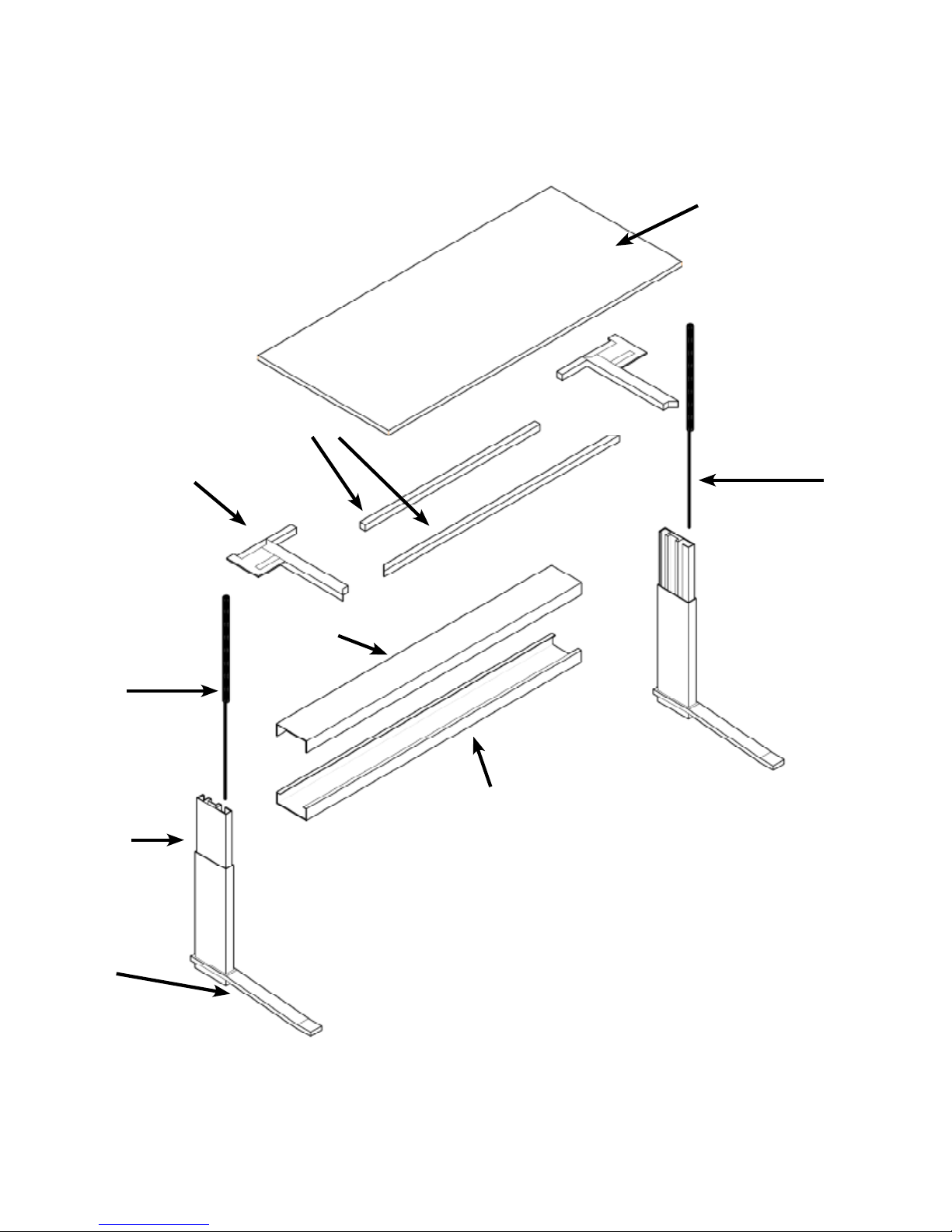
Exploded Desk Diagram
Hardware & Tools
Section 1: Basic Assembly of Desk
Shipped “KD” (knock down)
Unpack and Identify Parts
Assemble Cross Rail to Columns
Connecting Desktop Supports
to Columns
Assemble Work Surface
Support Frame
Attach Work Surface to
Support Frame
Replace Cross Rail Cover
and Trim
Attach Hand Lever
10
11
12
3
4
5
6
6
8
9
Section 2: Attaching the Desk 14
to the Lowboard/Pedestal
Attaching Desk to LowboardPedestal
Section 3: Accessories
Section 4: Care & Maintenance
FAQ & Troubleshooting
Section 5: Contact Us
15
17
19
22
Leveling and Calibrating Desk
eisys, inc. 112 28th Street South • Birmingham, Alabama 35233 • 205.941.1942 • www.eisys-inc.com
13
Support Frame Spanners
3
eisysDESKING
Work Surface
Support Frame
Gas Cylinder
Leg
Gas Cylinder
Cross Rail Cover
Cross Rail
Foot
eisys, inc. 112 28th Street South • Birmingham, Alabama 35233 • 205.941.1942 • www.eisys-inc.com
pic.1
eisysDESKING
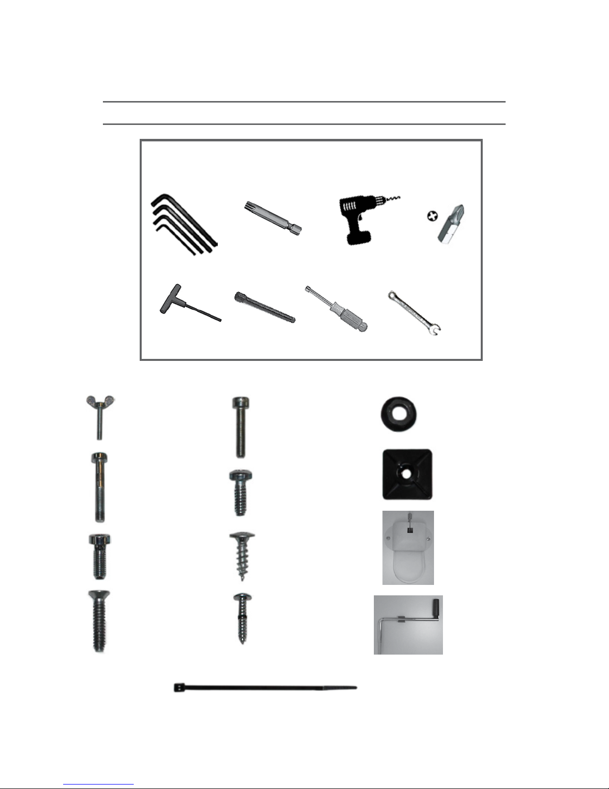
Tools and Hardware
Required and Recommended Tools
4
Metric Hex Wrenches
(3,4 & 5mm)
6” 4mm T-Handle
Hex Driver
Thumb Bolts —2 ea.
T25 Torx
Driver Bit
8” Driver
Extension
M5 x 20
Socket Cap Bolts —8 ea.
Cordless Driver
Drill
8mm Nut Driver or Box Wrench
#1 Phillips
Driver Bit
8mm Hex Nuts—8 ea.
Zip Tie Base—3ea.
M6 x 1.0 x 40
Socket Cap Bolts —4 ea.
M6 x 1.0 x 16
Socket Cap Bolts —4 ea.
M5 x 25
Flat Head Screws —8 ea.
eisys, inc. 112 28th Street South • Birmingham, Alabama 35233 • 205.941.1942 • www.eisys-inc.com
M5 x 16 TORX
Button Head s—8 ea.
20mm SPAX
Wood Screws—12 ea.
#4 x 16
Wood Screws —3 ea.
Hand Lever Control
Hand Crank (H2 only)
4” Zip Ties—3ea.

eisysDESKING
Section 1: Basic Assembly of Desk
Shipped “KD” (knock down)
-Pneumatic Version-
[H1-no calibration H2-weight compensation]
5
eisys, inc. 112 28th Street South • Birmingham, Alabama 35233 • 205.941.1942 • www.eisys-inc.com
Support Frame Spanners
Support Frame
Gas Cylinder
Cross Rail Cover
eisysDESKING
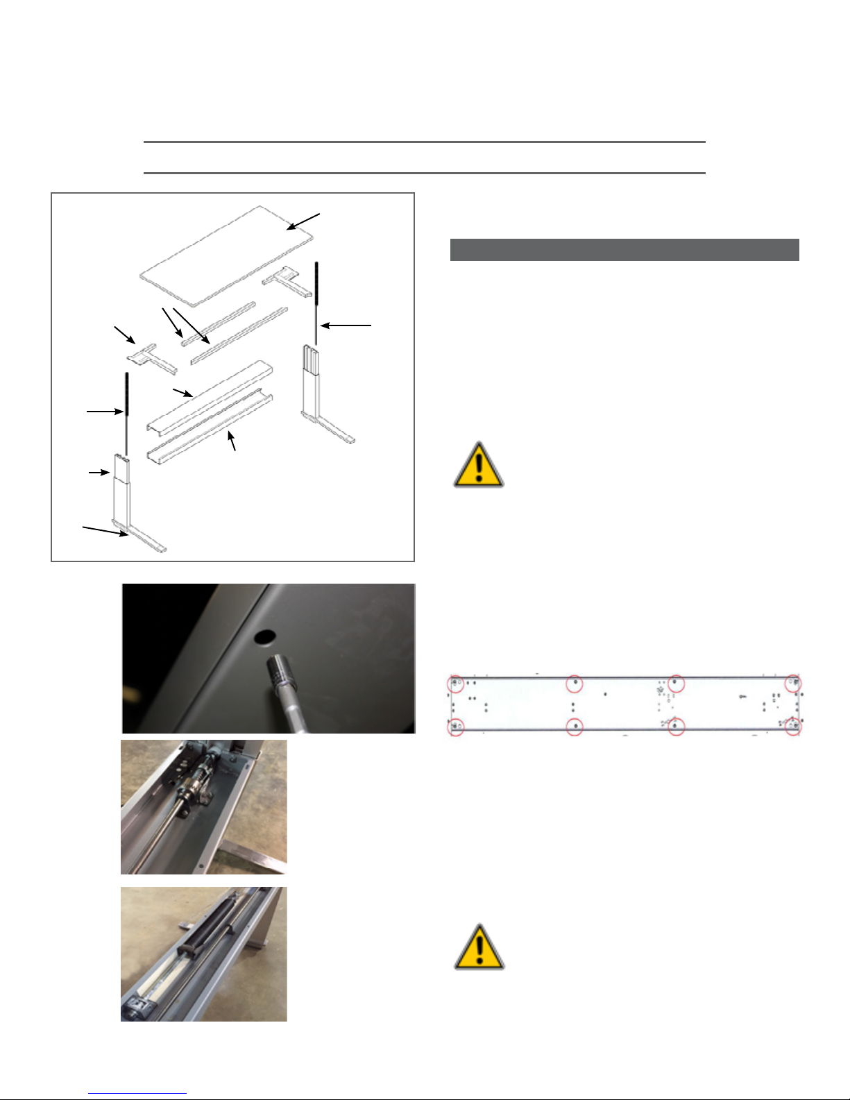
Basic Assembly of Desk Shipped “KD” (knock down)
1.
Work Surface
Gas Cylinder
Identify and uncrate ALL parts
(pic.1 )
NOTE:
1.Not all desks will require two gas cylinders.
The number of gas cylinders will depend on the
size and weight of desk top.
2. If user is providing their own custom top,
determine the weight of the top and contact
eisys to order the appropriate gas cylinders.
(This step should have been completed at
order entry).
6
Leg
Foot
Cross Rail
pic.4
pic.1
pic.2
Use caution when working with
compressed gas cylinders.
An uncontrolled release could
cause severe damage and/or
personal injury.
2.
Assembling Cross Rail to Columns (Legs)
a.
Use the 8mm nut driver or socket to remove
cross rail cover at indicated positions.
(pic.2-3 )
cross rail as seen from below
pic.3
After removing cover, note that H1 does not
b.
have a torsion spring. (pic.4)
H2 only, carefully examine the large torsion
spring to ensure it is in its fully relaxed
position (collapsed). (pic.4a)
eisys, inc. 112 28th Street South • Birmingham, Alabama 35233 • 205.941.1942 • www.eisys-inc.com
pic.4a
(H2 only)
WARNING!!! If torsion spring is
in a tight position (expanded)
STOP! Go to Section 5 and
contact eisys immediately!
eisysDESKING
Basic Assembly of Desk Shipped “KD” (knock down)
2.
Assembling Cross Rail to Columns (Legs)
(continued)
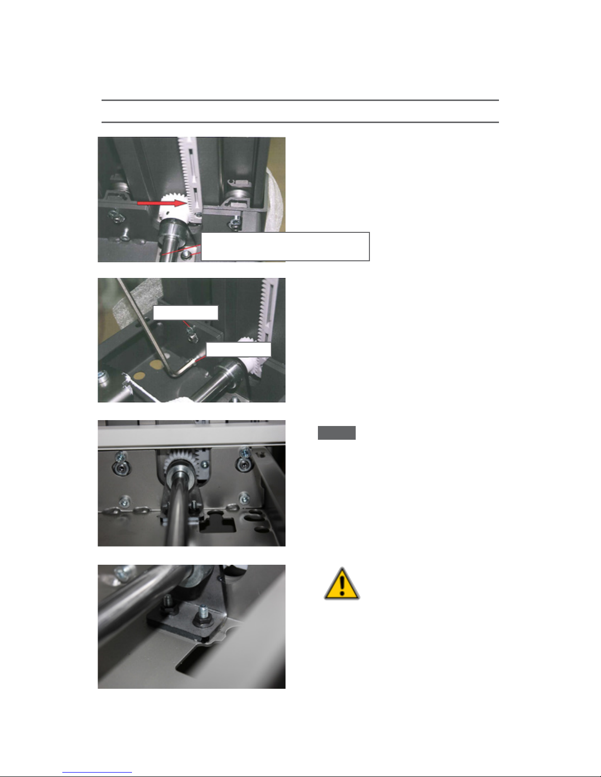
Using the 3mm & 8mm wrenches,
c.
loosen/remove the two drive shaft support
bracket bolts at each end of cross rail.
(pic.5 & pic.6)
screws for shaft support
screw from below cross rail
pic.5
long bolt
7
short bolt
pic.6
pic.7
d.
With the “inner leg” FULLY extended join
the cross rail to the leg and carefully insert
the gear into the track. (pic.5) Make sure the
inner leg is FULLY extended and the gear is
properly engaged with the track.
*TIP: The screw head at the end of the
*TIP:
geared track should be aligned with the
approximate center of the drive shaft/gear
when the leg is at max height. (pic.7)
Once cross rail is secured to legs, make sure
e.
the gear is seated with the geared track then
tighten shaft support bracket bolts. (pic.8)
CRITICAL!!! Make sure the
gears in both columns (legs)
are aligned at the exact same
position in each gear track per
above *TIP and picture 7.
eisys, inc. 112 28th Street South • Birmingham, Alabama 35233 • 205.941.1942 • www.eisys-inc.com
pic.8
 Loading...