

EisSound i500 Installation Manual
ENG
INSTALLATION MANUAL
Multiroom Audio System
500
i

Multiroom Audio System
500
i
2
installation manual
1.- Description and components of the i500 Series 3
2.- Pre-installation: previous recommendations 6
2.1.- Power Source 6
2.2.- Communication Line 6
2.3.- Line Reinforcement Module 6
2.4.- FM Tuners 7
2.5.- Coverage of Remote Control Unit 7
3.- Installing the Master Unit 9
3.1.- Connection to Communication Line 9
3.2.- Connection to Universal Dock for iPod 10
3.3.- Connection to External Sound Sources 10
4.- Installing Speakers in each zone 13
4.1.- Zone with Main Speaker (basic installation) 13
4.2.- Zone with Main Speaker (extended installation) 13
4.3 - Zone with Zone controller (basic installation)______________________________15
4.4 - Zone with Zone controller (extended installation)_____ 16
5.- Installation configuration 17
5.1.- Configuring each Main Speaker or Zone Controller
with its own Remote Control Unit ___________________________________ 17
5.2.- Configuring several Main Speakers or Zone Controllers
with the same Remote Control Unit 20
5.3.- Incorporate a new Remote Control Unit to the current System 21
5.4.- Other configuration options 23
6.- Reset the system with factory default settings 25
7.- Technical Characteristics 27
8.- Quick Reference Guide for Remote Control Unit Operation 29
Recommendations to achieve enhanced communication between the Remote
Control Unit and the Main Speaker or Zone Controller 30
iPod is trademark of Apple Inc. registered in teh U.S. and other countries.
"Made for iPod" means that an electronic accessory has been designed to connect specifically to iPod and has been certified by
Electrónica Integral de Sonido S.A. to meet Apple performance standards.
Apple is not responsible for the operation of this device or its compliance with safety and regulatory standards.
Electrónica Integral de Sonido S.A. is not responsible for any error or omissions that may appear in this manual, and reserves the right to
make changes without prior notice.
3
1. Description and components of the i500 Series
The i500 is a multi-room audio system for listeners to enjoy music throughout the entire home
by integrating the sound into the home’s fixtures. Thanks to its built-in ceiling speakers, the i500
series eliminates the need to have portable MP3 players or stand-along systems in each room.
The Serie is also equipped with intercom features for room-to-room communication, electronic
baby monitors, etc.
Some of the i500 Series features:
Enjoy music throughout the entire home, building.
Access different music channels, including a CD/DVD audio player and an iPod
docking station with full control allowing the user to navigate throughout a full 100
collection of music.
Wireless Remote Control Unit.
The i500 Series does not require hook-up from a dedicated computer. No technical computer
skills are required to fully enjoy all the features equipped to the system.
With the i500 Series it is possible to distribute different music channels to as many as 32
separate rooms from a Master Unit.
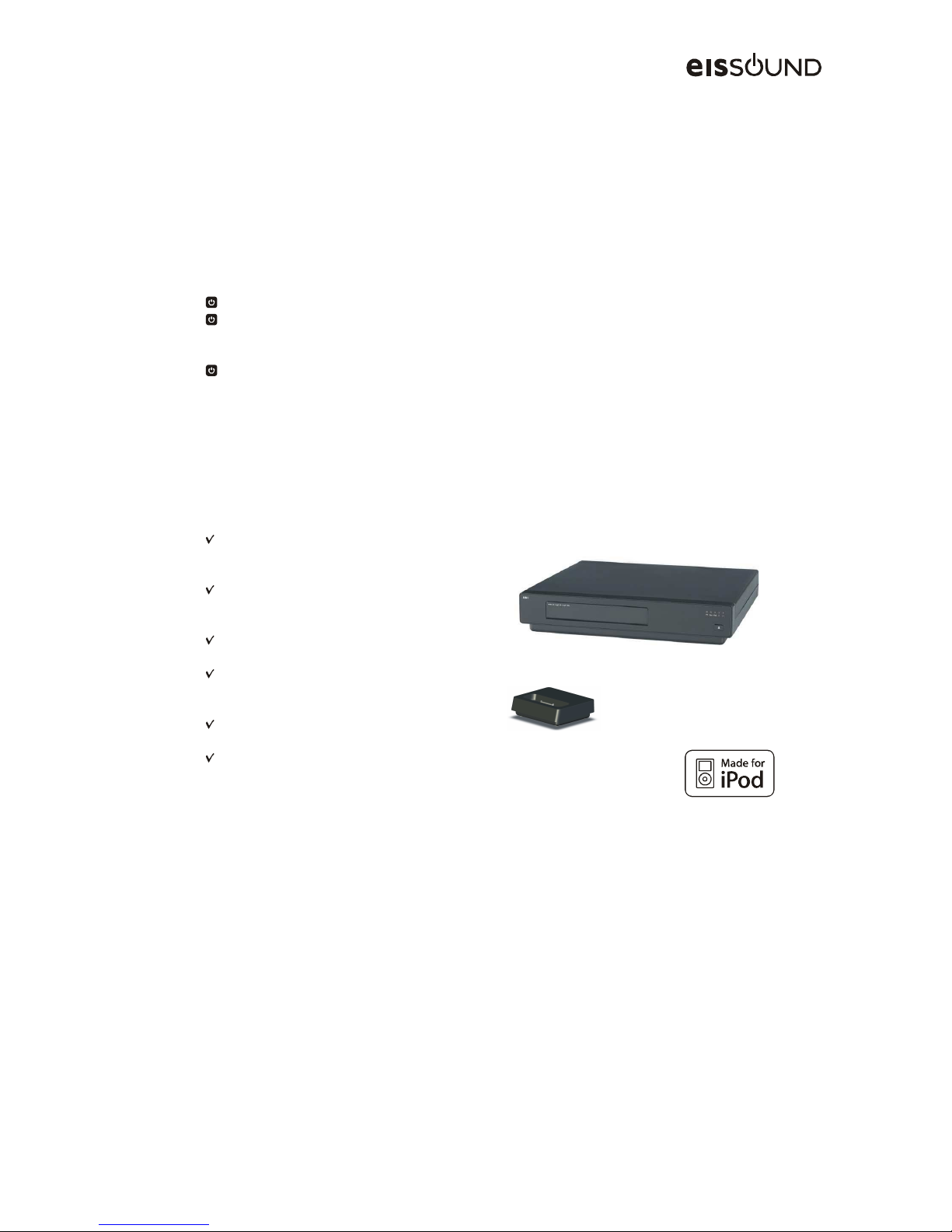
The Master Unit is equipped with the following features:
FM tuner with built-in RDS, 30
memories and RF 75 ohm coaxial
connectors for antenna
CD/DVD disc players able to
“reproduce” audio CD, CD-MP3 and
DVD-MP3
connection to Universal Dock for
iPod
two RCA inputs for external sound
devices with independent regulator
and level indicator
data and sound (4 channels) output
line via RJ45 connector
direct connection to the electrical
mains (110 to 240Vac/35W)
A Main Speaker (ref. 551 01) and a Passive Speaker (ref. 553 01) are installed in each zone or
room. Flush-mounted in the ceiling, they become integrated into the home without the need for
entertainment centers, counters or any other type of external fixture.
There is also the option to install a Zone Controller (ref. 557 22) which can be connected to a
external Speakers and Amplifiers.
A bus-type cable connection is required to communicate the Master Unit with all the Main
Speakers and Zone Controllers within the system. The wired connection provides optimal sound
quality reception, free of interference and interruptions, thus guaranteeing total privacy from
possible intrusions (involuntary or intentional) from outside the home.
Multiroom Audio System
500
i
4
installation manual
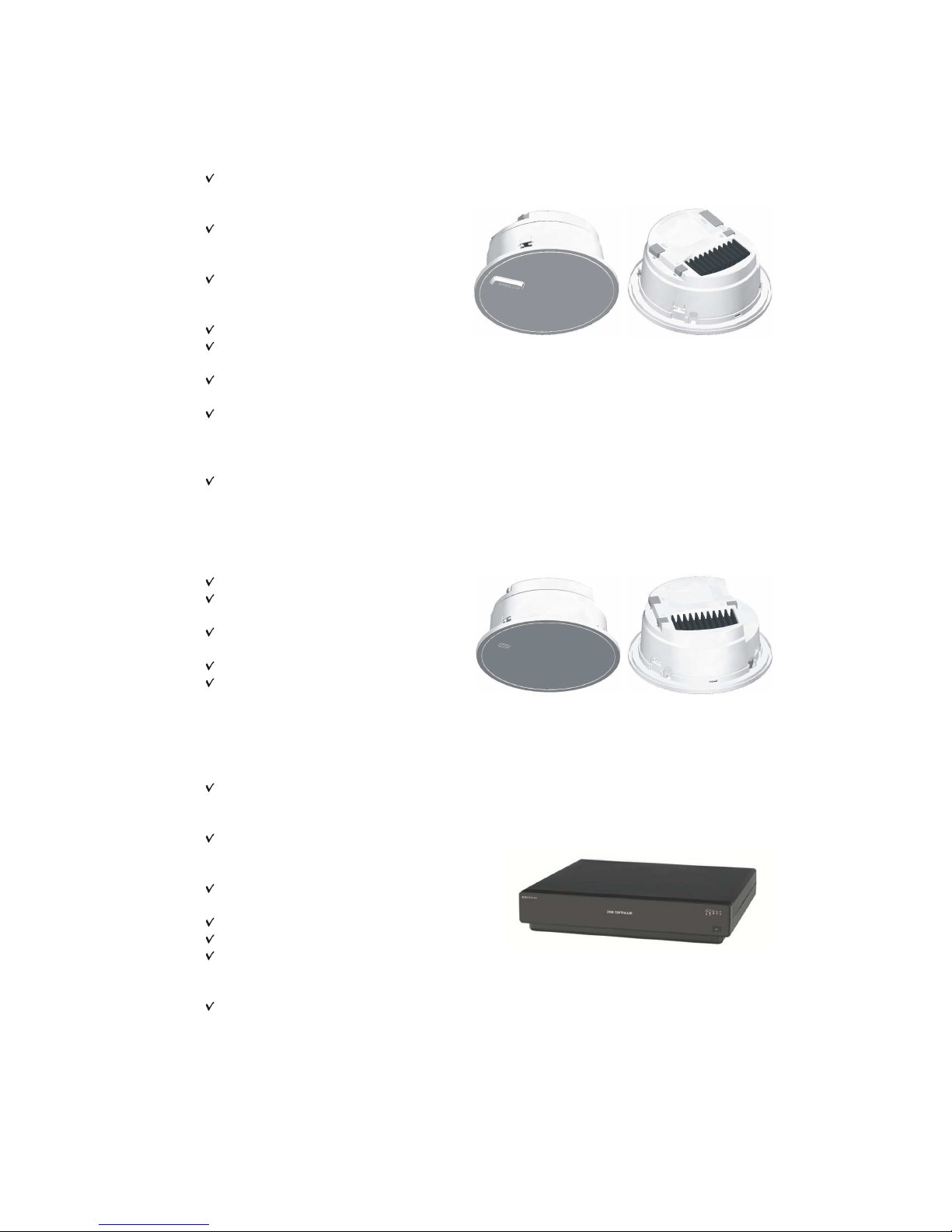
The Main Speaker (ref. 551 01) integrates the control and sound electronics of each zone or
room and is equipped with the following basic features:
FM tuner with built-in RDS, 30
memories and 75 ohm RF
coaxial antenna connector
wireless data and sound
communication with Remote
Control Unit
data and sound (4 channels)
input line from the Master
Unit: 8 wires
5+5W sound amplifier
built-in 8 ohm two-way
loudspeaker
8 ohm output for Passive
Speaker (ref. 553 01)
line output (4 wires) for
Auxiliary Speaker (ref. 552
01) or any other external
amplifier
connection to the electrical
mains (110 to 240Vac/20W)
The Auxiliary Speaker (ref. 552 01) is ideal for zones or rooms where greater sound power is
required. Its features include:
5+5W sound amplifier
built-in 8 ohm two-way
loudspeaker
8 ohm output for Passive
Speaker (ref. 553 01)
line input (4 wires)
connection to electrical mains
(110 to 240Vac/18W)
The Zone Controller (ref. 557 22) integrates all electronic and sound controls of each room or
area, presenting the following basic features:
FM tuner with built-in RDS, 30
memories and 75 ohm RF coaxial
antenna connector
wireless data and sound
communication with Remote
Control Unit
data and sound (4 channels) input
line from the Master Unit: 8 wires
15+15W sound amplifier
8 ohm output for Speaker
line output (4 wires) for Auxiliary
Speaker (ref. 552 01) or any other
external amplifier
connection to the electrical mains
(110 to 240Vac/20W)

5
The entire system is managed from Remote Control Units. They do not require any installation.
The Remote Control Unit Base needs be connected to the mains. It acts as the Remote’s
platform as well as providing battery charge for the Remote Control Unit:
graphic interface with 2.2” color TFT
built-in microphone
3.5 mm input jack for external sound
source
wireless data and sound communication
with Main Active Speaker (ref. 551 01)
battery charger connected to the
electrical mains (110 to 240Vac/5W)
Only use Base supplied to charge Remote Control Unit batteries.
There is also the possibility to control de i500
Series from external KNX devices. For this
option is necessary to add to the installation
the KNX i500 Interface module (ref. 534 95)
and the figure of a KNX Integrator to design
and personalize the interface according to
the user’s needs.
3
ROOM
ROOM
CENTRAL
L2
CENTRAL
CENTRAL CENTRAL
ch 1
the image above is an example of i500 series
integration with KNX system and JUNG
FP701CTIP touch screen
Finally, i500 Series Central Unit has a RS232 port through which can be access to control to a
large part of the system's performance. Thanks to ASCII command language is possible to
make a user interface to control the i500 series from other external devices such as iPhone,
iPad, etc.
In any case, keep always in mind that total control of the system only can be carried out from
the Remote Controls, so it will at least always be necessary to have one in each installation.

Multiroom Audio System
500
i
6
installation manual
2. Pre-installation:
previous recommendations
The i500 Series requires basic pre-installation. To avoid future issues and ensure optimal
system operation, follow these recommendations.
2.1. Power Source
Main Speakers (ref. 551 01) and Auxiliary Speakers (ref. 552 01) must be connected to the
mains through wires with PVC isolation according to IEC60227 (H05VV-F 3G 0,75mm
2
) or
alternatively with synthetic rubber according to IEC60245 (H05RR-F 3G 0,75mm
2
).
We recommend that the power source for the Master Unit, Main
Speakers and Auxiliary Speakers and Zone Controllers be from the
same automatic switch in order to facilitate isolation and disconnection
of the sound system independent from the rest of the home’s electrical
consumption. This will also avoid signal reception and sound
interference with other appliances such as extractor fans, air
conditioning, refrigerators, fans and the like (see wiring diagram in
sections 3.1, 4.1 and 4.2).
Installation of Main Active Speakers (ref. 551 01) and Auxiliary Active Speakers (ref. 552 01)
must performed in the way that, once installed, mains connection must not be accesible by
user.
For Master Unit, Zone Controllers and Remote Control Base plug is the disconnection device,
so they must be easily accessible.
IMPORTANT do not supply power to the system until it is correctly installed and
connected.
2.2. Communication Line
The communication line is an 8 wire connecting hose that connects the Master Unit to all Main
Speakers and all Zone Controllers.
To make the connection 4 (yellow) use 1mm
2
cross-section wires. For the remaining
connections use 0.25mm
2
cross-section wires. It may be necessary to increase the wire crosssection in systems with a large number of units and/or greater distances. In this case, consult
with EISSOUND Technical Service.
Bus-type communication line distribution is necessary to keep the length of the shunts to each
Main Speaker (“stub”) to the minimum. This is especially important in systems greater than 100
meters and/or ten Main Speakers. In smaller systems, star or mixed connections are possible.
2.3. Line Reinforcement module
It may be necessary to use a Line Reinforcement module in some cases. This module would
be plugged into the Main Active Speaker (ref. 551 01).
The location of the device is very important:
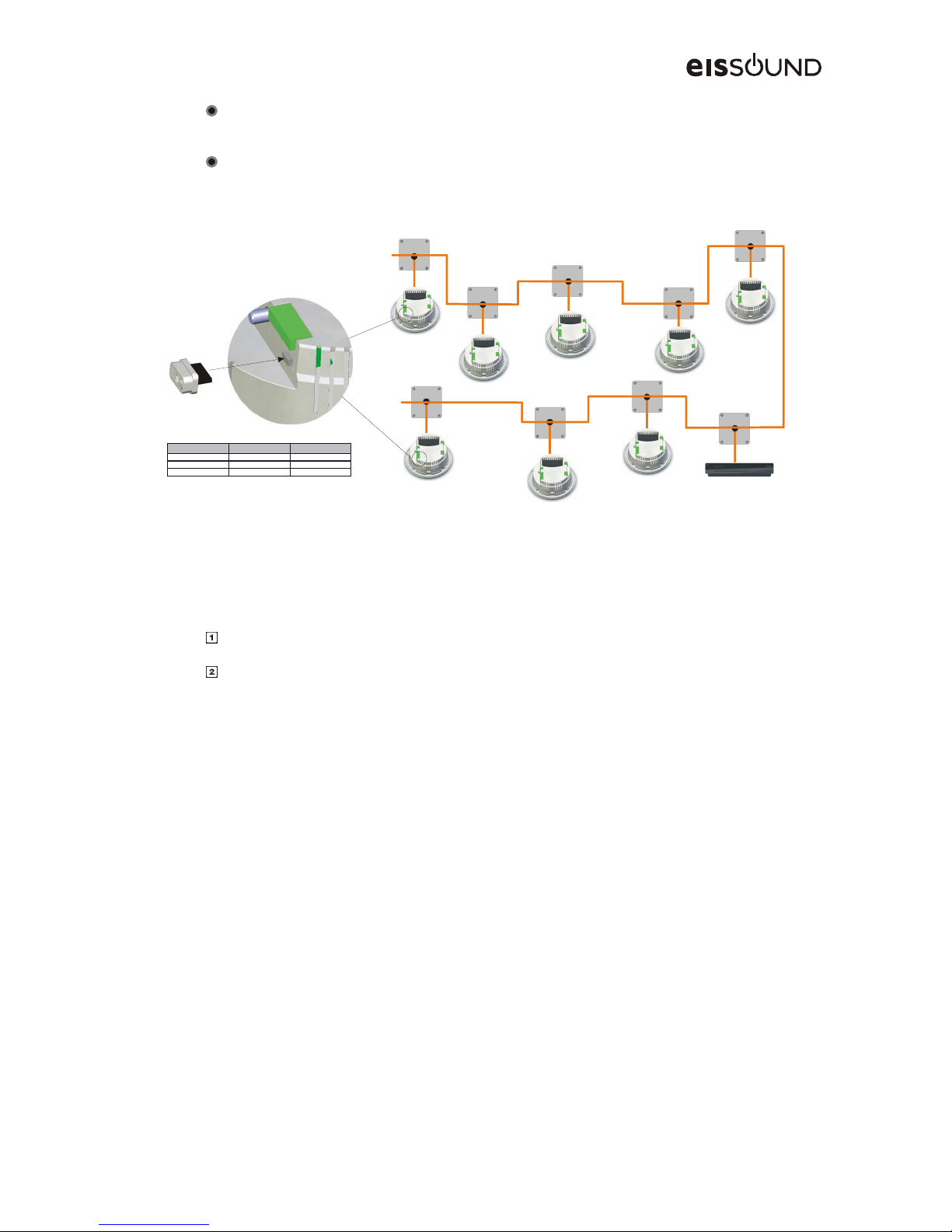
7
In a bus-type system it should be installed in one or both ends of the system (see the
figure).
In star or mixed type systems look for the longest straight path between two points and
install the device on one or both ends of the system.
installation lengt h # Main Active Speaker s # Line Reinfo rcemen Devices
0..100m 0..10 0
100..200m 10..20 1
200..600m 20..32 2
2.4. FM Tuners
The installation of the 75 ohm FM antenna must be according to adequate techniques of
installation and signal distribution for antennas:
Ensure that the FM band amplifier is in the header of the antenna installation.
The installation should include as many distributors as necessary to reach all antenna
feeds in the Master Unit and Main Speakers and Zone Controllers.
The reception of RDS information is more demanding in terms of signal/noise compare to a
simple FM signal. As a result in some areas where signal reception is not optimal it may not be
possible to receive RDS information. Also, not all stations broadcast RDS information so the
RDS function may not always be available.
In areas where FM signal is strong enough the antenna may be replaced by a simple 76cm long
wire inserted into the nucleus of the ANT connector. In this event, the wire should be placed as
far away as possible from sources of electromagnetic interference such as motors, contact
units, relays, fluorescents, halogens, and the like.
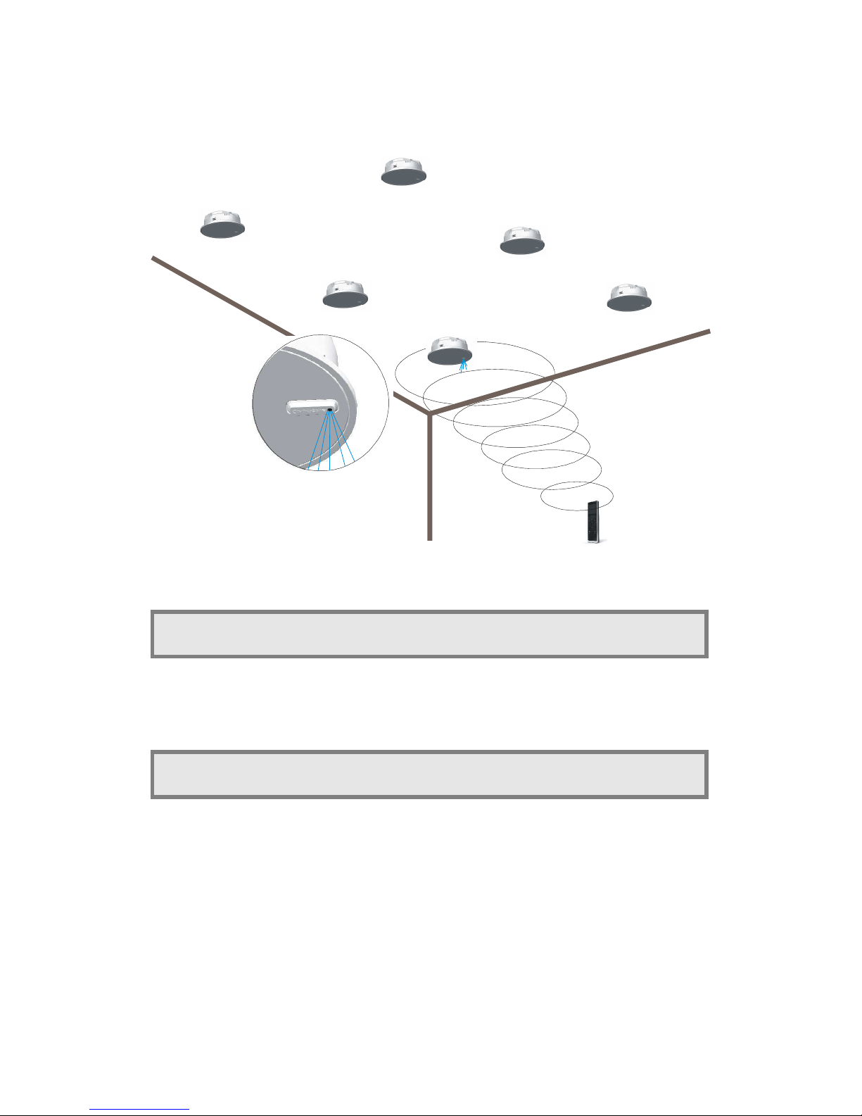
2.5. Coverage of Remote Control Unit
The entire system is operated by using the Remote Control Units installed in each of the zones
or rooms included in the system.
It is VERY IMPORTANT to carefully choose the location of the Main Speaker and the Zone
Controller when planning the pre-installation. Place the Main Speaker and Zone Controller in a
preferential location in the room, as clear as possible from any obstacles, especially metallic
objects.
Multiroom Audio System
500
i
8
installation manual
The Main Speaker (ref. 551 01) is visually recognized from the rest of the Speakers
by the antenna capsule and the blue LED integrated in the front grille.
The location of the remaining Speakers (Auxiliary Speakers ref. 552 01 and Passive Speakers
ref. 553 01) does not affect the coverage of the Remote Control Unit.
To facilitate communication between the Remote Control Unit and the Main Speaker
or Zone Controller follow all the recommendations in section 8.
9
3. Installing the Master Unit
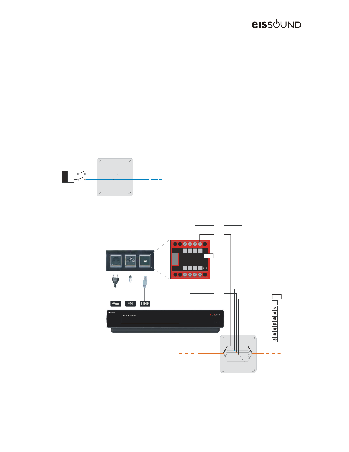
3.1. Connection to Communication LINE
The Master Unit is connected to the communication line by means of a Line Connector module
(ref. 573x1). The cable supplied with the Master Unit must be specifically used for this
connection.
The Line Connector module is available in several colours and can be fitted with the most
popular electrical switch brands by using the adapters listed in the EISSOUND catalog (BJC,
Jung, Legrand, Niessen, Schneider, Simón, bTicino, ...).
Connection to the power supply is made with the cable supplied with the Master Unit (see
installation recommendations in section 2.1).
The Master Unit has a 75 ohm antenna input for the built-in FM tuner (see section 2.3).
595758
4
545352
51
White
Black
Violet
Brown
Orange
Blue
Green
Yellow
LINE
573x1
L N
230V
4
LINE
White
Black
Violet
Brown
Orange
Blue
Green
Yellow

Multiroom Audio System
500
i
10
installation manual
3.2. Connection to Universal Dock for iPod
To access music stored in an iPod, the Master Unit is equipped with a back panel connection to
the Universal Dock for iPod. The connection is only available with this Unit and should not used
for any other purpose.
LEVEL
LEVEL
LINE
FM
L2
L1
Pod
PORT
IR
!
3.3. Connection to External Sound Sources
On its back panel, Master Unit is equipped with 2 RCA inputs to connect 2 external sound
sources as L1 and L2.
External L1 sound input shares the signal with the iPod. The iPod always has
priority. As a result, the music connected to L1 is only available when the iPod dock
is not connected.
The maximum allowable length for this connection depends on the external devices that supply
the signal (consult the manufacturer’s technical specifications). The length tends to vary
between 1 and 10m. The input signal level can be adjusted using a dimmer together with a
LED.
LEVEL
LEVEL
LINE
FM
L2
L1
Pod
PORT
IR
!
There are three alternatives for connecting an external sound source to the Master Unit:
(1) Preferably use the music system line out as an external sound source. This output
ensures a constant signal which is independent of the system’s volume control.
 Loading...