

EisSound 400 Series, 414A1, 414A2 User And Installation Manual

USER'S AND INSTALLATION MANUAL
400 SERIES
CC-1023ENG-10

1
1. Quick Reference Guide
2. 400 Series Overview
3. Central
5
6
8
10
12
13
14
15
16
18
19
21
23
24
24
26
30
31
32
33
33
33
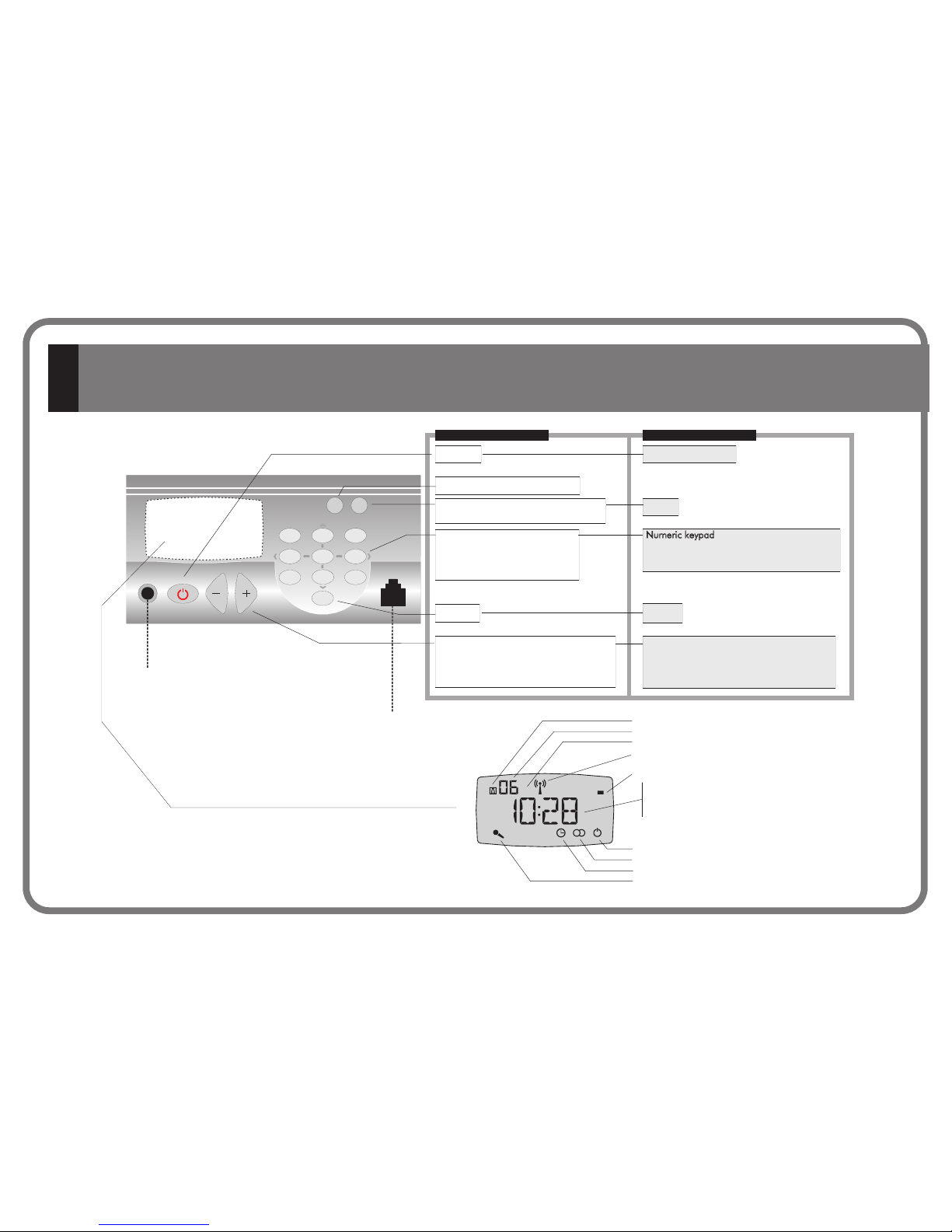
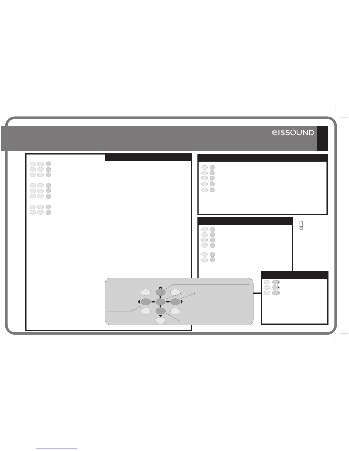
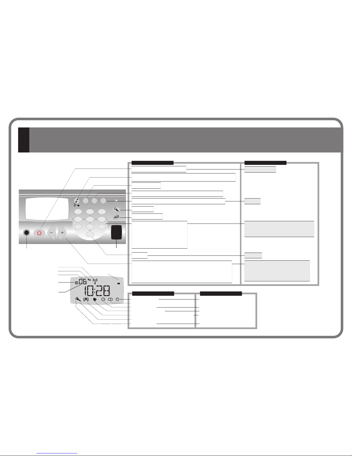
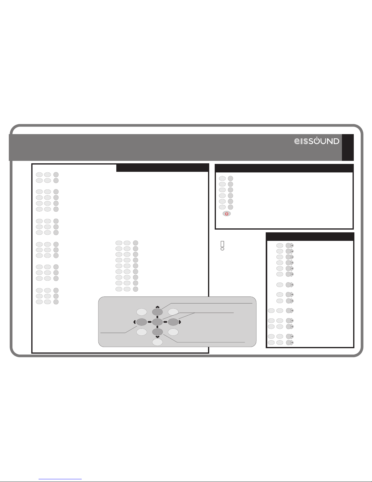
1.1. Master Unit
1.2. Control Unit
1.3. Control Unit
1.4. Control Unit
2.1. Introduction
.2 .400 S
2.3. Connecting Terminals
2.4. Basic Wiring Diagram
2.5. General Installation Notes
2.6. Programming Menus
2.7. Music channels
3.1. Master Unit
3.1.1. Operation
3.1.2. Program Menu
3.1.3. Settings Menu
3.1.4. Installation Menu
3.1.5. Technical Specifications
3.2. Sound Input Unit
3.2.1. Description
3.2.2. Technical Specifications
414A1/A2
422A1/A2
428A1+42991
428A1/A4 , 428A1+42992
414A1/A2
41591/92
2 eries Components 15
3.3. Power Supply Unit
3.3.1. Description
3.3.2. Technical Specifications
4.1. Control Unit
4.1.1. The first time...
4.1.2. Operating audio functions
4.1.3. Operating intercom calls functions
4.1.4. Control Unit : Program Menu
4.1.5. Control Unit : Settings Menu
4.1.6. Control Unit : Installation Menu
4.1.7. Control Unit : Program Menu
4.1.8. Control Unit : Installation Menu
4.1.9. Technical Specifications
4.2. Control Unit
4.2.1. The first time...
4.2.2. Operating audio functions
4.2.3. Operating intercom calls functions
4.2.4. Program Menu
4.2.5. Installation Menu
4.2.6. Remote control operation
4.2.7. Technical Specifications
11295/96/99, 11204
422A1/A2 & 428A1+42991
422A1/A2
422A1/A2
422A1/A2
428A1+42991
428A1+42991
428A1/A4 & 428A1+42992
34
34
34
35
35
36
37
46
53
60
62
65
70
74
75
76
76
81
88
92
97
98
4. Control Unit
400 SERIES
CC-1023ENG-10
2
MASTER UNIT
414A1/A2
414A1/A2
CONTROL UNIT
422A1/A2
422A1/A2
1.1. Quick Reference Guide Master Unit 414A1/A2
2. 400 Series Overview
3. Central
6
13
14
15
16
18
19
21
23
24
24
26
30
31
32
33
33
33
34
34
34
2.1. Introduction
.2.
2.3. Connecting Terminals
2.4. Basic Wiring Diagram
2.5. General Installation Notes
2.6. Programming Menus
2.7. Music channels
3.1. Master Unit 414A1/A2
3.1.1. Operation
3.1.2. Program Menu
3.1.3. Settings Menu
3.1.4. Installation Menu
3.1.5. Technical Specifications
3.2. Sound Input Unit 41591/92
3.2.1. Description
3.2.2. Technical Specifications
3.3. Power Supply Unit 11295/96/99, 11204
3.3.1. Description
3.3.2. Technical Specifications
2 400 Series Components 15
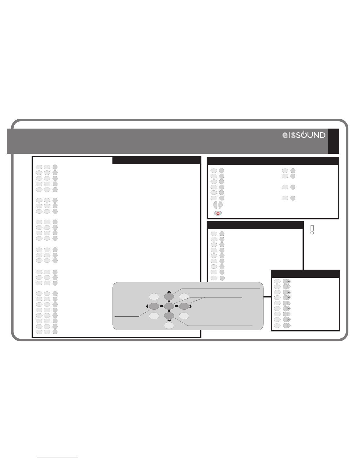
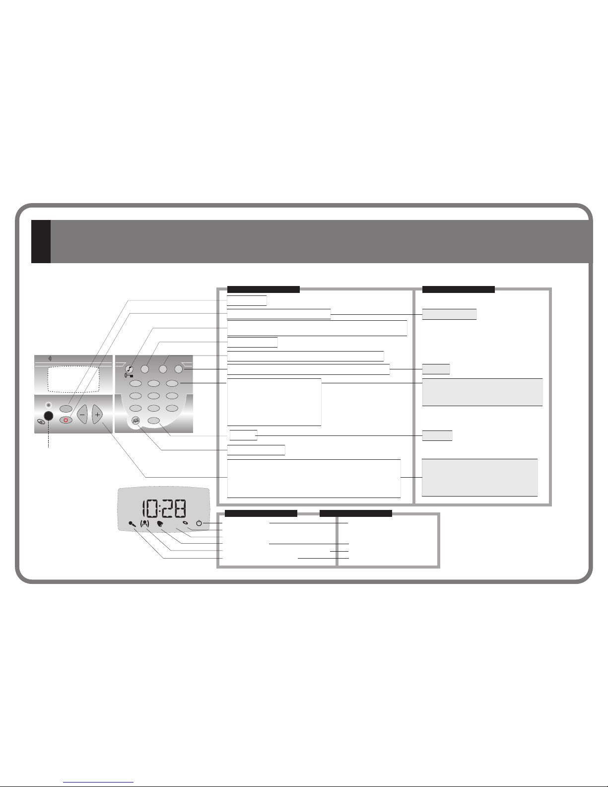
1.2. Quick Reference Guide Control Unit 422A1/A2
2. 400 Series Overview
4.1. Control Unit 422A1/A2
8
13
14
15
16
18
19
21
35
36
37
46
53
60
62
74
2.1. Introduction
.2.
2.3. Connecting Terminals
2.4. Basic Wiring Diagram
2.5. General Installation Notes
2.6. Programming Menus
2.7. Music channels
4.1.1. The first time...
4.1.2. Operating audio functions
4.1.3. Operating intercom calls functions
4.1.4. Control Unit 422A1/A2: Program Menu
4.1.5. Control Unit 422A1/A2: Settings Menu
4.1.6. Control Unit 422A1/A2: Installation Menu
4.1.9. Technical Specifications
2 400 Series Components 15
CC-1023ENG-10
3
1.3. Quick Reference Guide Control Unit
2. 400 Series Overview
4.1. Control Unit 428A1+42991
428A1+42991 10
13
14
15
16
18
19
21
35
36
37
46
65
70
74
2.1. Introduction
.2.
2.3. Connecting Terminals
2.4. Basic Wiring Diagram
2.5. General Installation Notes
2.6. Programming Menus
2.7. Music channels
4.1.1. The first time...
4.1.2. Operating audio functions
4.1.3. Operating intercom calls functions
4.1.7. Control Unit 428A1+42991: Program Menu
4.1.8. Control Unit 428A1+42991: Installation Menu
4.1.9. Technical Specifications
2 400 Series Components 15
1.4. Quick Reference Guide Control Unit
2. 400 Series Overview
4.2. Control Unit 428A1+42992
428A1+4299212
13
14
15
16
18
19
21
75
76
76
81
88
92
97
98
2.1. Introduction
.2.
2.3. Connecting Terminals
2.4. Basic Wiring Diagram
2.5. General Installation Notes
2.6. Programming Menus
2.7. Music channels
4.2.1. The first time...
4.2.2. Operating audio functions
4.2.3. Operating intercom calls functions
4.2.4. Program Menu
4.2.5. Installation Menu
4.2.6. Remote control operation
4.2.7. Technical Specifications
2 400 Series Components 15
42991
428A1
CONTROL UNIT
428A1+42991
42992
428A1
CONTROL UNIT
428A1+42992
CC-1023ENG-10
2
4
1.4. Quick Reference Guide Control Unit 428A1/A4
2. 400 Series Overview
4.2. Control Unit 428A1/A4
12
13
14
15
16
18
19
21
75
76
76
81
88
92
98
2.1. Introduction
.2.
2.3. Connecting Terminals
2.4. Basic Wiring Diagram
2.5. General Installation Notes
2.6. Programming Menus
2.7. Music channels
4.2.1. The first time...
4.2.2. Operating audio functions
4.2.3. Operating intercom calls functions
4.2.4. Program Menu
4.2.5. Installation Menu
4.2.7. Technical Specifications
2 400 Series Components 15
428A1/A4
CONTROL UNIT
428A1/A4
CC-1023ENG-10

5
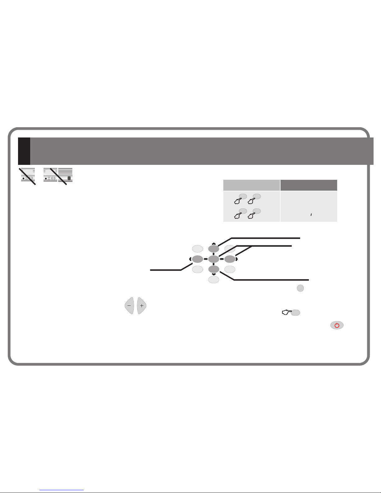
1. Quick Reference Guide
CC-1023ENG-10
21
54
87
0
C
3
6
9
abc
jkl
ghi
pqrs
tuv
def
mno
wxyz
FM
PRG
CONTROL UNIT
ON / OFF
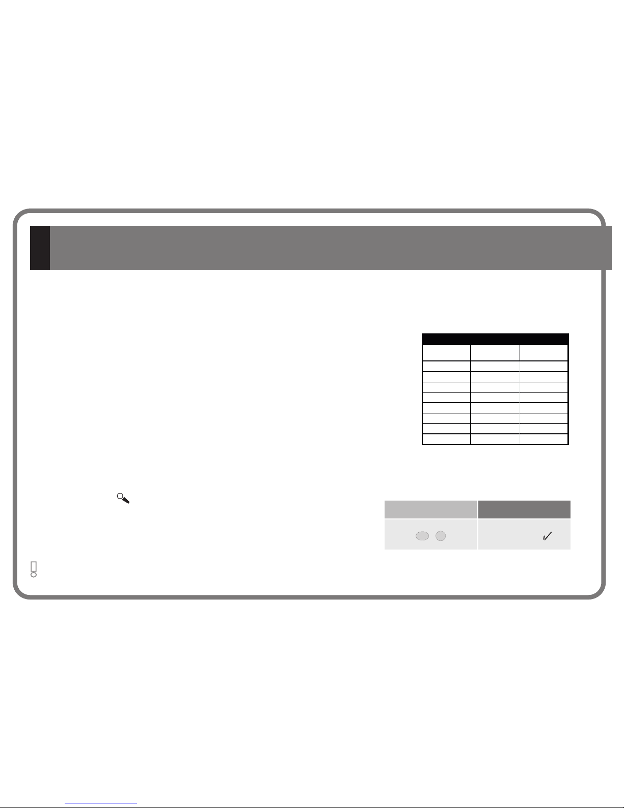
Master Unit tuner control
Access to program menus / settings /
installationn
Numeric keypad
PC interface connector
Discman/MP3/iPod
414A1 1 (terminal 10)
2 (terminal 20)
input
Master Unit without FM tuner ( ): channel
Master Unit with FM tuner (414A2): channel
Detele
ON/OFF
Store
Numeric keypad
Detele
Exit program menu
NORMAL
PROGRAMMING
6
FM station frequency
FM memory pre-sets
Programming options
Numeric selection of program setting
Scroll through the programming options
Adjust keys
Automatic station search
Frequency band forward/reverse
Adjust keys
Selection of program setting
Scroll through options available in the
same programming level
Power on
Day of the week
- time
- date
- information
Pre-set memory selected
Master Unit FM tuner memory pre-sets
FM station tuned
FM
1
4
3
2
7
6
5
Master Unit FM tuner
FM stereo station tuned
Auto-power off activated
Intercom Calls channel busy
1.1. Master Unit 414A1/A2
CC-1023ENG-10
7
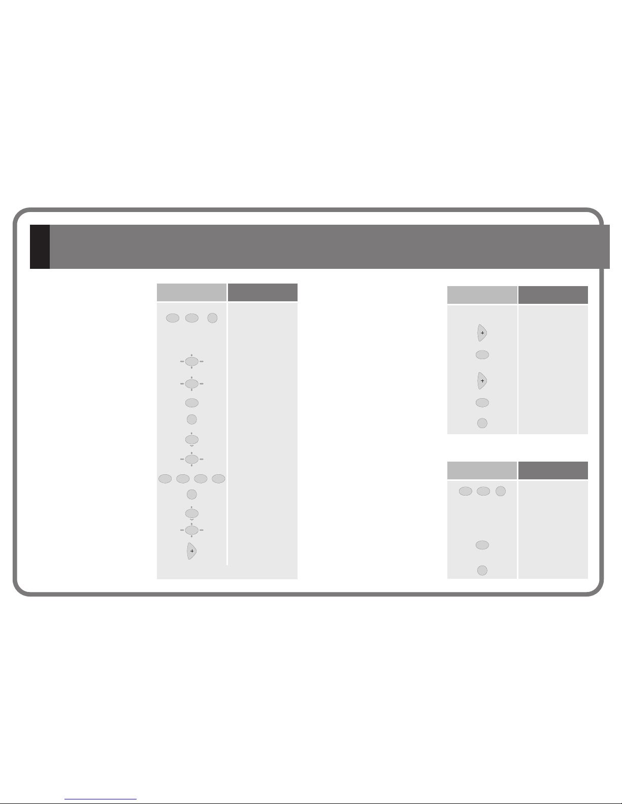
CLOCKS
FM TUNER
ADJUSTMENTS
Time (Hour, minutes - Days, month, year)
Auto power on (ON/OFF - Hour, minutes - Days of week)
Auto power off (ON/OFF - Hour, minutes - Days of week)
FM search sensitivity - Master Unit (4=max ... 1=min)
Delete FM tuning pre-sets - Master Unit
Autoscan
Dimmer off
Dimmer on
1
1
1
1
2
abc
2
abc
2
abc
2
abc
3
def
PRG
PRG
PRG
1
2
abc
3
def
3
def
3
def
PRG
PRG
PRG
1
2
abc
PRG
PRG
PROGRAM MENU
Auto power ON/OFF
Release intercom calls channel
Enable/disable telecontrol function
All zones Standby
Clear the baby monitor throughout the system
4
ghi
3
def
PRG
PRG
PRG
PRG
PRG
9
wxyz
7
pqrs
(2") Language
(2") Master Unit name
(2") Master Unit greeting
(2") Permission to store/delete FM tuning
pre-sets - Master Unit
(2") General Standby permission
(2") Delete settings
6
mno
1
2
abc
5
jkl
4
ghi
3
def
PRG
PRG
PRG
PRG
PRG
PRG
SETTINGS MENU
INSTALLATION MENU
(2") Channel number
(2") Delete installation
(2") Software version
1
2
abc
3
def
PRG
PRG
PRG
QUICK ACCESS FUNCTIONS
(2")
indicate to
hold a key
down for 2
seconds
21
54
8
7
0
C
3
6
9
abc
jkl
ghi
pqrs
tuv
def
mno
wxyz
Scroll back to the previous option within the
same level.
enter the level
exit the level
Scroll forward to the next option
within the same level.
6
mno
CC-1023ENG-10
21
54
87
0
C
3
6
9
abc
jkl
ghi
pqrs
tuv
def
mno
wxyz
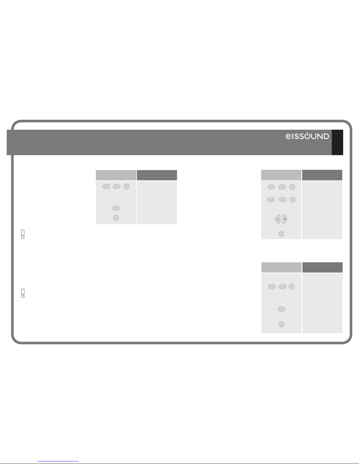
CH FM
PRG
ON / OFF
IR receiver
discman/MP3/iPod input
(channel #7)
Store
Detele
Exit program menu
ON/OFF - end intercom calls operation
Channel selection
Access to program menus / settings / installation
Intercom calls
Group call selection
Numeric keypad
Delete
Numeric keypad
weekday
local FM tuner memory
pre-set
channel/memory pre-set
selected
FM station tuned
local FM tuner
music channel
1 2
music activated
FM stereo tuned station
master power supply disabled
sleep activated auto-power-off activated
alarm 1-2 activated
alarm 1-2 activated and lagging
no permission to receive intercom calls do not disturb
transmitting intercom calls
Baby Monitor
voice detector
FM
1
4
3
2
7
6
5
NORMAL
STATIC FLASHING
PROGRAMMING
8
Audio adjust mode (volume - bass - treble - loudness - balance)
open the door
Local FM tuner operation (channel 0) - Master Unit (channel 1)
Station frequency
FM memory pre-sets
Channel
Programming options
Intercom Call zone identification
Numeric selection of program setting
Scroll through the programming options
Audio levels (volume - bass - treble - loudness - balance)
Channel
Automatic station search
Frequency band forward/reverse
Adjust keysAdjust keys
Selection of program setting
Scroll through options of the same
programming level
1.2. Control Unit 422A1/A2
CC-1023ENG-10
169
CLOCKS
Alarm 1 (ON/OFF status - Hour, minutes - Days of week - Type - Volume)
Alarm 2 (ON/OFF status - Hour, minutes - Days of week - Type - Volume)
Auto Standby (ON/OFF status - Hour, minutes - Days of week)
Sleep
Time (Hour, minutes - Day, month, year)
FM TUNER
FM Search sensitivity (4=max ... 1=min)
Delete FM tuning pre-sets
Autoscan
RECEIVE INTERCOM CALLS
Volume
Individual call
Group call
General call
TRANSMIT INTERCOM CALLS
General call
Baby Monitor (ON/OFF status - Sensitivity - Time - Destination address)
Auto response (ON/OFF status - Sensitivity - Time)
ADJUSTMENTS
Store “IDEAL” settings
Dimmer off
Dimmer on
CHANNEL IDENTIFICATION NAME
FM local tuner name
channel #1 name
channel #2 name
channel #3 name
channel #4 name
channel #5 name
channel #6 name
discman/MP3/iPod channel name
1
1
1
1
1
1
2
abc
2
abc
2
abc
2
abc
5
jkl
5
jkl
5
jkl
5
jkl
4
ghi
4
ghi
4
ghi
4
ghi
3
def
6
mno
6
mno
6
mno
6
mno
6
mno
6
mno
6
mno
6
mno
PRG
PRG
PRG
PRG
PRG
1
2
abc
3
def
3
def
3
def
3
def
3
def
PRG
PRG
PRG
1
1
1
2
abc
2
abc
2
abc
4
ghi
3
def
3
def
PRG
PRG
PRG
PRG
PRG
PRG
PRG
PRG
7
pqrs
8
tuv
6
mno
3
def
1
2
abc
5
jkl
4
ghi
3
def
PRG
PRG
PRG
PRG
PRG
PRG
PRG
PRG
PRG
PRG
PROGRAM MENU
Alarm 1 status ON/OFF
Alarm 2 status ON/OFF
Autostandby status ON/OFF
Baby Monitor status ON/OFF
Redial directory
Activate Ideal mode
(2") Activate Sleep
Do not disturb status ON/OFF
6
mno
1
2
abc
5
jkl
4
ghi
3
def
PRG
PRG
PRG
PRG
PRG
PRG
All zones Standby
Store “Ideal”
Clear the Baby
Monitor throughout
all zones
Consult zone #,
name and group
0
C
9
wxyz
7
pqrs
8
tuv
PRG
PRG
PRG
PRG
QUICK ACCESS FUNCTIONS
(2") Language
(2") Control Unit name identification
(2") Control Unit greeting
(2") Permission to receive intercom calls
(2") Access to FM tuner-Master Unit
(2") Permission to store/delete FM pre-sets
(2") General Standby permission
(2") IR remote Control Unit
(2") Delete settings
9
wxyz
7
pqrs
8
tuv
6
mno
1
2
abc
5
jkl
4
ghi
3
def
PRG
PRG
PRG
PRG
PRG
PRG
PRG
PRG
PRG
SETTINGS MENU
INSTALLATION MENU
(2")Zone identification
(2") Group
(2") Mono/Stereo
(2") Audio output
(2") Permission intercom
(2") Perm. Baby Mon.
(2") Channel number
(2") Delete installation
(2") Software version
9
wxyz
7
pqrs
8
tuv
6
mno
1
2
abc
5
jkl
4
ghi
3
def
PRG
PRG
PRG
PRG
PRG
PRG
PRG
PRG
PRG
(2")
indicate to
hold a key
down for 2
seconds
21
54
8
7
0
C
3
6
9
abc
jkl
ghi
pqrs
tuv
def
mno
wxyz
Scroll back to the previous option within the
same level.
enter the level
exit the level
Scroll forward to the next option
within the same level.
CC-1023ENG-10
Store
Detele
Exit program menu
ON/OFF - end intercom calls operation
Intercom calls
Numeric keypad
Delete
Numeric keypad
NORMAL
FM local tuner
music channel
alarm activated
alarm activated and lagging
FM
STATIC FLASHING
PROGRAMMING
10
DISPL AY UNIT
EIS
MIC
1
0
C
2
abc
5
jkl
4
ghi
7
m
pqrs
8
tuv
3
def
6
mno
9
wxyz
CH
FM
PRG
ZONES KE YPAD
discman/MP3/iPod input
(channel #7)
Audio adjust mode (volume - bass - treble - loudness - balance)
Open the door
Channel selection
Local FM tuner operation (channel 0) - Master Unit (channel 1)
Access to program menu / settings / installation
Station frequency
FM memory pre-sets
Channel
Programming options
Intercom Call zone identification
Numeric selection of program setting
Scroll through the programming options
Group call selection
Audio levels (volume - bass - treble - loudness - balance)
Channel
Automatic station search
Frequency band forward/reverse
Adjust keys
Adjust keys
Selection of program setting
Scroll through options of the same
programming level
music activated master power supply disabled
transmitting intercom calls Baby Monitor
no permission to receive intercom calls
do not disturb
1.3. Control Unit 428A1+42991
CC-1023ENG-10
18
11
CLOCKS
ALARM
FM TUNER
INTERCOM CALLS
BABY MONITOR
ADJUSTMENTS
Hour, minutes
Day, month, year
ON/OFF
Hour, minutes
Type
Volume
FM Search sensitivity (4=max ... 1=min)
Delete FM tuning pre-sets
Autoscan
Do not disturb
Volume
Auto-response ON/OFF
ON/OFF status
Identification
Sensitivity
Language
Dimmer on
Dimmer off
SETTING OPTIONS
Control Unit name identification
FM local tuner name
channel #1 name
channel #2 name
channel #3 name
channel #4 name
channel #5 name
channel #6 name
discman/MP3/iPod channel name
111
2
abc
2
abc
2
abc
2
abc
2
abc
5
jkl
5
jkl
5
jkl
4
ghi
4
ghi
4
ghi
6
mno
6
mno
6
mno
PRG
PRG
1
2
abc
3
def
3
def
3
def
3
def
PRG
PRG
PRG
1
1
1
2
abc
2
abc
2
abc
3
def
3
def
PRG
PRG
PRG
PRG
PRG
PRG
PRG
7
pqrs
7
pqrs
7
pqrs
7
pqrs
7
pqrs
7
pqrs
7
pqrs
7
pqrs
7
pqrs
7
pqrs
8
tuv
6
mno
3
def
1
1
2
abc
2
abc
5
jkl
4
ghi
4
ghi
3
def
3
def
PRG
PRG
PRG
PRG
PRG
PRG
PRG
PRG
PRG
PRG
PRG
PRG
PRG
PRG
PRG
PROGRAM MENU
Alarm status ON/OFF
Do not disturb status ON/OFF
Baby Monitor status ON/OFF
General Standby for all zones
Clear the baby monitor throughout the system
Consult zone #, name and group
(2") Activate Sleep
1
5
jkl
4
ghi
PRG
PRG
PRG
PRG
PRG
PRG
0
C
9
wxyz
7
pqrs
(2") Zone identification
(2") Group
(2") Mono/Stereo
(2") Audio output
(2") Channel number
(2") Permission to transmit
intercom calls
(2") Permission to receive
intercom calls
(2") Baby Monitor permission
(2") Access to FM tuner-
Master Unit
(2") General Standby
permission
(2") Auto-response sensitivity
(2") Auto-response silence
time
(2") Delete installation
(2") Software version
9
wxyz
7
pqrs
8
tuv
6
mno
1
2
abc
2
abc
5
jkl
4
ghi
4
ghi
3
def
3
def
PRG
PRG
PRG
PRG
PRG
PRG
PRG
PRG
PRG
PRG
PRG
PRG
PRG
PRG
9
wxyz
1
1 1
1
1
1
0
C
QUICK ACCESS FUNCTIONS
INSTALLATION MENU
(2") indicate
to hold a key
down for 2
seconds
21
54
8
7
0
C
3
6
9
abc
jkl
ghi
pqrs
tuv
def
mno
wxyz
Scroll back to the previous option within the
same level.
enter the level
exit the level
Scroll forward to the next option
within the same level.
CC-1023ENG-10
2
Master Unit FM tuner
music channel
alarm activated
alarm activated and lagging
STATIC FLASHING
music activated master power supply disabled
transmitting intercom calls Baby Monitor
no permission to receive intercom calls
do not disturb
12
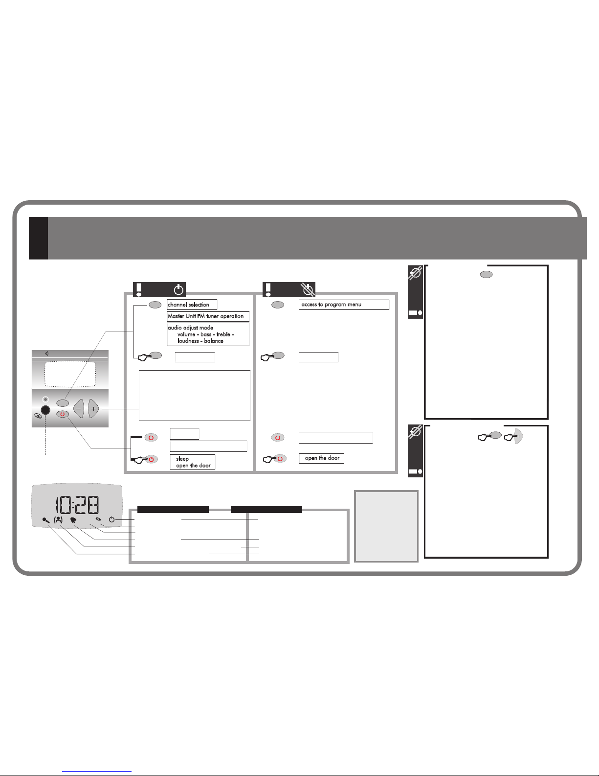
ON/OFF
end intercom calls operation
end intercom calls operation
audio adjust mode
volume - bass - treble loudness - balance
channel selection
Master Unit FM tuner operation
access to program menu
intercom calls intercom calls
DISPL AY UNIT
EIS
MIC
m
discman/MP3/iPod input (channel #7)
(1) Depends on
installation
options
(2) Depends on
the connection to
the Master Unit
(3) Not available
mod.428A1
m
- Alarm ON/OFF status
- Alarm time (hour-min)
- Alarm type
- Alarm volume
- FM Search sensitivity
- Delete FM tuning pre-sets
- Autoscan
- Do not disturb
- Intercom calls volume
- Auto-response ON/OFF status
- Baby Monitor ON/OFF status
- Baby Monitor identification
- Baby Monitor sensitivity
- Language
- Dimmer off level
- Dimmer on level
PROGRAM
OPTIONS
m
2’’
m
m
2’’
m
sleep
open the door
open the door
adjust keys
audio levels (volume - bass - treble -
loudness - balance)
channel
Master Unit FM tuner pre-set
intercom call zone identification
parameter programmable
2’’
2’’
INSTALLATION
OPTIONS
m
2’’
FM
- Zone identification
- Group
- Mono/Stereo
- Audio output
- Channel number
- Permission to transmit intercom calls
- Permission to receive intercom calls
- Baby Monitor permission
- Access to FM tuner-Master Unit
- Auto-response sensitivity
- Auto-response silence time
- Delete installation
- Software version
1 428A1 , 428A4 , 428A1+42992.4. Control Unit
control
unit OFF
control
unit OFF
control
unit OFF
control
unit ON
(2)
(2)
(2)
(2)
(3)
(3)
(3)
(2) (1)
(1)(2)
(1)(2)
(1)(2)
(1)(2)
(1)(2)
CC-1023ENG-10

13
2. 400 series overview
CC-1023ENG-10
2. 400 Series Overview
Highlights of the 400 Series include:
The 400 Series is flexible, allowing the user to tailor the
feature settings to customized needs. It is also sophisticated,
providing three programming levels: Installer Level, Settings
Level and User Level for the configuration and differentiation
of its applications, before, during and after installation.
Ø
Ø
Ø
Ø
Ø
Ø
Ø
Ø
Multiple languages. Bigger alpha and numeric characters on
display screen. Adjustable dimmer for ON/OFF position (10
levels)
Standby of system executable from any Control Unit
Redial directory
Direct keying in of selected FM station tuning, automatic storing
the best FM stations, …
... and over 30 functions you’ll discover in this manual
General intercom calls (both group and individual calls) with
vox-control hands-free automatic response. Ability to code 250
zones and 250 different groups.
Vox-control electronic baby monitor.
Automatic adjustment of microphone sensitivity (without the
need for volume control). Ability to program adjustment of
activation sensitivity for automatic response and for electronic
baby monitor (each feature independently).
The new 400 Series has arrived with optimal features and unparalleled quality. It showcases conspicuous and compact design especially tailored to the
user. A superb ergonomic blending of the keypad and the screen icons make understanding its operation easy. It was designed for intuitive operation
by the user through clear and easily accessible menus.
The 400 Series was designed to provide a sound system for residential, commercial and business use. The system is flexible and can easily be adapted
or extended. Being compatible with the EISSOUND Universal Line 100 Series, the new 400 Series control units are now also adaptable to most major
electrical mechanisms.
14
2.1 Introduction
CC-1023ENG-10
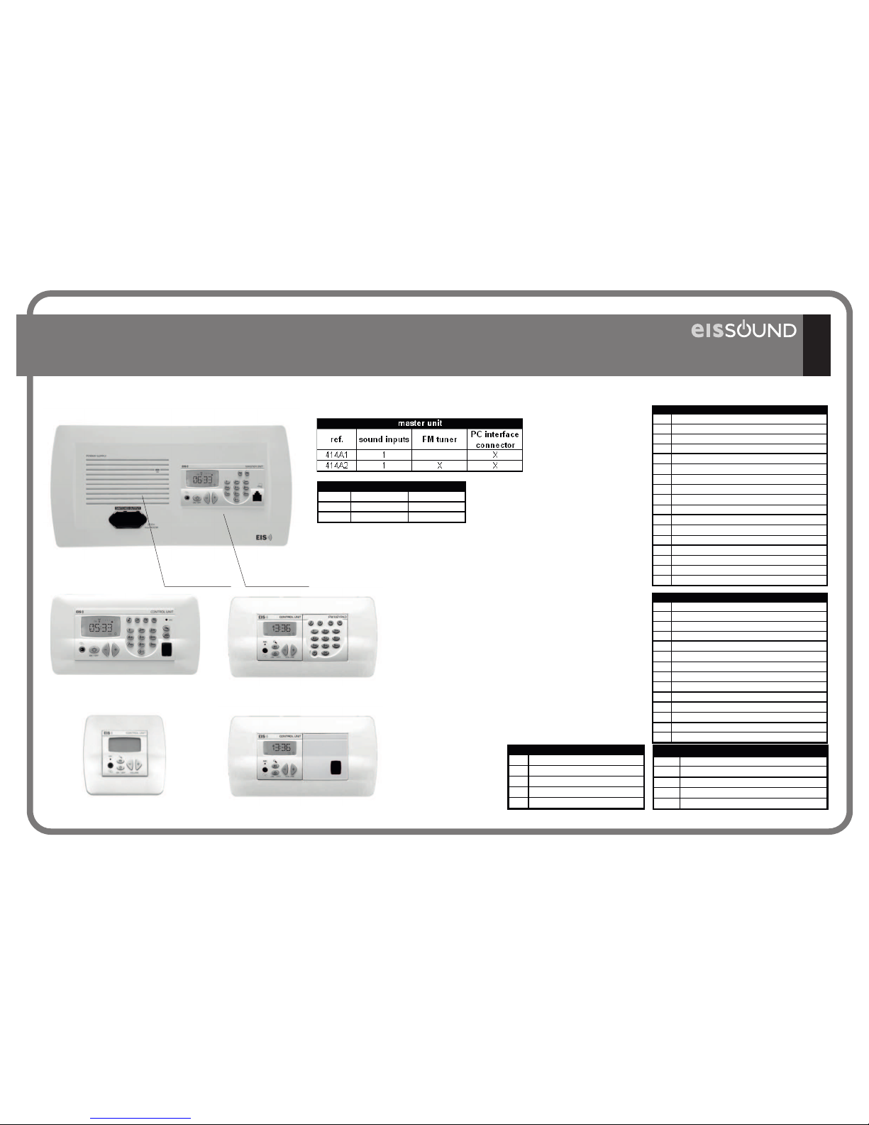
ref. power type
11295 14W r eg.
11296 30W switch
power supply
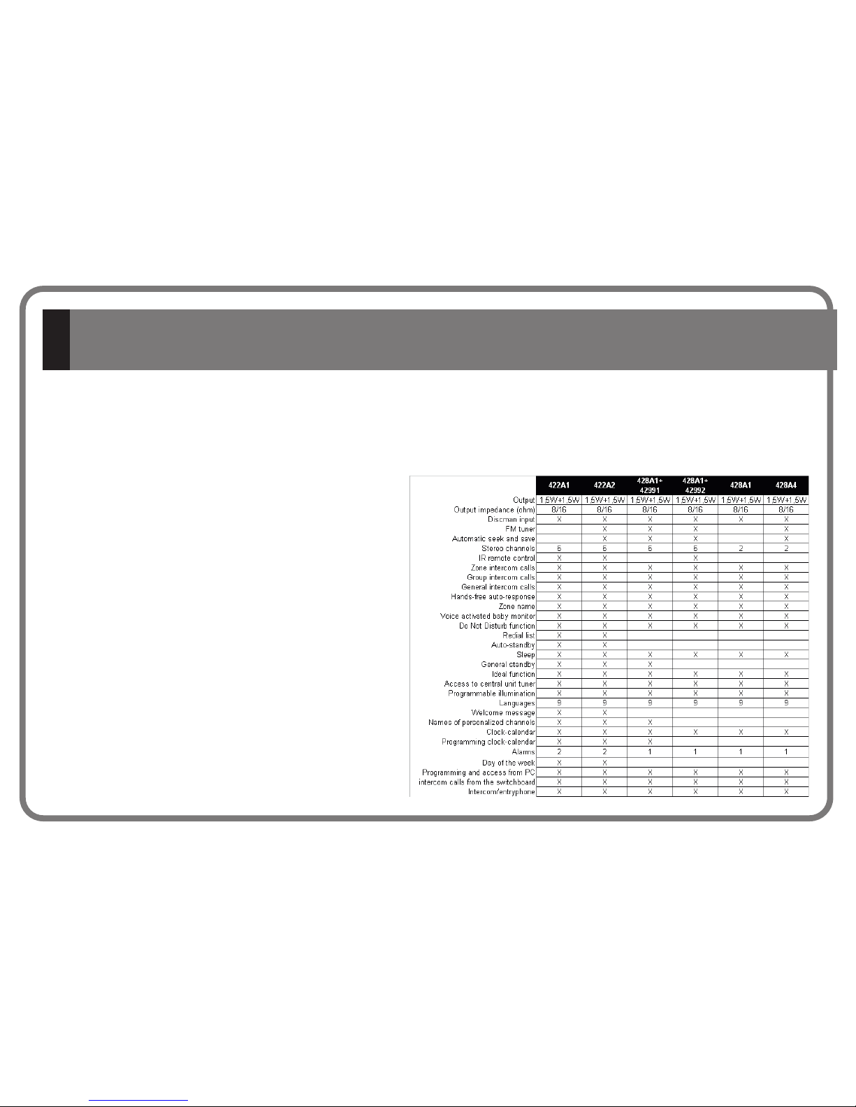
2.2. 400 Series Components
15
2.3. Connecting Terminals
1
Standby power voltage
4
Mass
02
Activation of power supply power-on
03
Telecontrol signal
91
Data (+)
92
Data (-)
7
Intercom calls signal
10
MPX sound channel output, music program #1
20
MPX sound channel output, music program #2
A
FM antenna
M
FM antenna mass
N
Neutral power supply from current network 230V
F
Phase power supply from current network 230V
F'
Telecontrol network base phase 230V
Master Unit & Power Supply
2
Supply voltage
4
Mass
91
Data (+)
92
Data (-)
93
Data (IR)
7
Intercom calls signal
10
MPX sound channel input, music program #1
20
MPX sound channel input, music program #2
30
MPX sound channel input, music program #3
40
MPX sound channel input, music program #4
50
MPX sound channel input, music program #5
60
MPX sound channel input, music program #6
05
Left channel speaker output (+)
06
Right channel speaker output (+)
04
Mass fot speakers of both channels (-)
A
FM antenna
M
FM antenna mass
Unit Control
2
Supply voltage
4
Mass
X0
MPX sound channel output
L
Left channel input
R
Right channel input
Sound Input
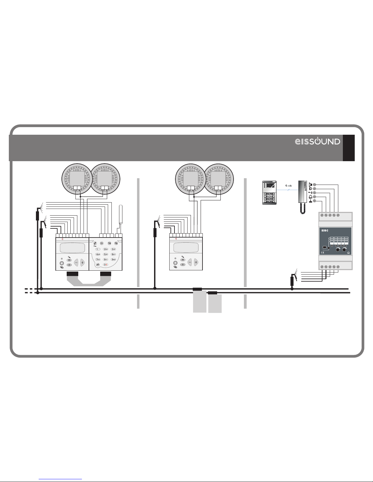
80
Mass
81
Intercom line
82
Door opening line
83
Intercom/entryphone loudspeaker line
84
Intercom/entryphone microphone line
entryphone intercom interface
428A1+42992428A1/A4
428A1+42991
414A1/A2
422A1/A2
11295/96
CC-1023ENG-10
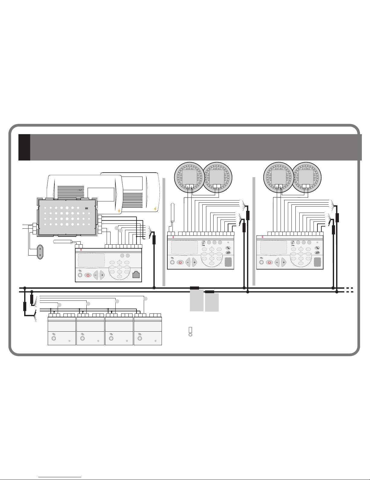
2.4. Basic Wiring Diagram
Left Left
Right Right
Other wiring diagram variations are discussed in the “Wiring
Diagram Manual”.
16
EIS
POWER SUPPLY
ON
EIS
POWER SUPPLY
TELECONTROL SOCKET
220V. max 400W
F
F’
N
02
4
03
2
1
220V
16 ohm
-
+
16 ohm
-
+
16 ohm
+
-
16 ohm
+
-
Ver
Ver
Ver
Ver
Ver
Ver
Ver
Az
Az
Az
Az
Az
Az
Az
Am
Am
Am
Am
Am
Am
Am
Na
Na
Na
Na
Na
Na
Na
Bl
Bl
Bl
Bl
Ma
Ma
Ma
Vio
Vio
Vio
Vio
Ro
Ro
Ro
Ro
Ro
Ro
Ro
414A2
41591
41592
(x4)
11295
11296
194_5
194_4
M Y0 921002 4A 20 91703 1
MASTER UNIT
ON / OFF
EIS
FM
PRG
3
6
9
def
mno
wxyz
1
4
7
ghi
pqrs
2
5
8
0
C
abc
jkl
tuv
X02 ML4 R
SOUND SOURCE
LEVEL
X02 ML4 R
SOUND SOURCE
LEVEL
X02 ML4 R
SOUND SOURCE
LEVEL
X02 ML4 R
SOUND SOURCE
LEVEL
171 05
171 05
171 05
171 05
171 03
171 03
171 03
10
20
50
60
40
30
422A1
171 03
92105005 600693 42030 9174004 2
CONTROL UNIT
ON / OFF
MIC
EIS
CH FM
PRG
3
6
9
def
mno
wxyz
1
4
7
ghi
pqrs
2
5
8
0
C
abc
jkl
tuv
422A2
92105005 600693 4M 2030 9174004 2A
CONTROL UNIT
ON / OFF
MIC
EIS
CH FM
PRG
3
6
9
def
mno
wxyz
1
4
7
ghi
pqrs
2
5
8
0
C
abc
jkl
tuv
171 05
2 = Red
4 = Yelllow
91 = White
92 = Orange
7 = Violet
10 = Green
20 = Blue
171 03
- = Brown
- = Red
30 = Orange
40 = Yellow
50 = Green
60 = Blue
COAX.ANT.
COAX.ANT.
CC-1023ENG-10
17
16 ohm
-
+
16 ohm
+
-
16 ohm
-
+
16 ohm
+
-
Ver
Ver
Ver
Ver
Az
Az
Az
Az
Am
Am
Am
Am
Na
Na
Na
Na
Bl
Bl
Bl
Ma
Vio
Vio
Vio
Ro
Ro
Ro
Ro
428A1
92 10 05 06
4
2091
7
04
2
CONTROL UNIT
ON / OFF
MIC
VOLUME
EIS
171 05
171 05
171 05
171 03
428A1 42991
92 10 05 06
4
2091
7
04
2
CONTROL UNIT
ON / OFF
MIC
VOLUME
EIS
50 60
M
30
40
A
FM KEYPAD
80 81 82 83 84
2 4 91 92 7
43494
PRG
SPK MIC
ONOFF
INTERFACE DOOR
DOOR
ALLGR
MICSPKCALL
TONEONPRG
PRG
PRG
REP
ZONE
Y/N
MODEL43494
171 05
2 = Red
4 = Yelllow
91 = White
92 = Orange
7 = Violet
10 = Green
20 = Blue
171 03
- = Brown
- = Red
30 = Orange
40 = Yellow
50 = Green
60 = Blue
LeftLeft
RightRight
COAX.ANT.
CC-1023ENG-10
2.5. General Installation Notes
£
£
£
£
£
£
£
£
£
A 400 Series system consists of two basic elements: a CENTRAL UNIT and several
CONTROL UNITS.
The CENTRAL UNIT can be placed anywhere in the system and consists in one or
more Power Supply Units a Master Unit 414A1/A2 and, optionally, several Sound
Input Units 41591/92
Tuner of 414A2 Master Unit will be defaulted to channel #1 (terminal 10).
Channel #2 (terminal 20) will be the Master Unit’s discman/MP3/iPod input. The
additional audio channels should be connected consecutively using terminals 30,
40, ...
Master Units not equipped with tuners (414A1) will use channel #1 for the
discman/MP3/iPod input (terminal 10). The rest of audio channels should be
connected consecutively using terminals 20, 30 ...
The number of channels used should be configured on the Master Unit (see
3.14.A.Number of Audio Channels Installed).
If the room is monophonic, connect any of the speakers and set the Control Unit
to MONO (see 4.1.6.C. Control Unit Installation: Mono/Stereo).
8 ohm speakers can be connected to the Control Unit outputs. The Control Unit
must be set to 8 in this case (see 4.1.6.D. Control Unit Installation: Audio
Output).
To connect the FM antenna, connect a 76 cm wire to terminal A or connect a
75 antenna input to terminals A (signal) and M (mass).
If it is necessary to connect an amplifier or power stage to a Control Unit’s
output, this Control Unit must be set to AMPLIFIER (see 4.1.6.D. Control Unit
Installation: Audio Output). Connect the amplifier to terminals 2, 4, 05 and 06
on the Control Unit (see “ )
ohm
W
Wiring Diagram Manual”
£
£
£
£
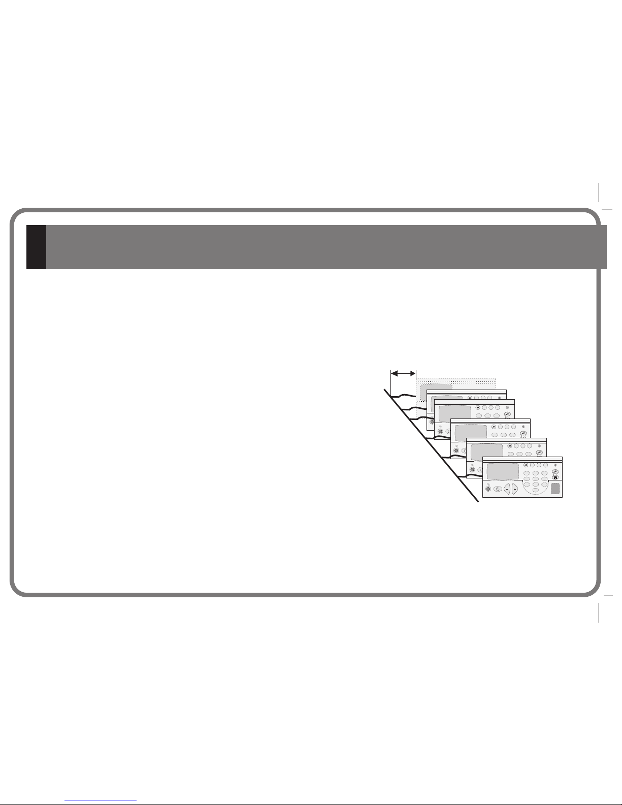
If the size of the installation requires the use of several
power supply units, the different rooms should be
divided in terms of the size of the power supplies.
Rooms are connected to 2 and 4 of each supply.
It is advisable to keep the primary line shunts as short
as possible.
Consult the manufacturer regarding installations of
over 600 meters and/or 60 Control Units.
All wire sections are 0.25 mm except supply wires
(terminals 2 and 4), which are 1 mm. The network
tapping wires are standard.
11
4
7
2
5
8
0
3
6
9
GHI
PQRS
ABC
JKL
TUV
ON
OFF
DEF
MNO
WXYZ
C FM
PGM
11
4
7
2
5
8
0
3
6
9
GHI
PQRS
ABC
JKL
TUV
ON
OFF
DEF
MNO
WXYZ
C FM
PGM
11
4
7
2
5
8
0
3
6
9
GHI
PQRS
ABC
JKL
TUV
ON
OFF
DEF
MNO
WXYZ
C FM
PGM
11
4
7
2
5
8
0
3
6
9
GHI
PQRS
ABC
JKL
TUV
ON
OFF
DEF
MNO
WXYZ
C FM
PGM
11
4
7
2
5
8
0
3
6
9
GHI
PQRS
ABC
JKL
TUV
ON
OFF
DEF
MNO
WXYZ
C FM
PGM
min. length
up to 120 Control Units
18
CC-1023ENG-10
display
Installation menu
Settings menu
Program menu
The 414A1/A2 Master Units and the 422A1/A2 Control Units have three program menus of
settings at different access levels.
Discusses the settings related to the proper operation of the system.
These settings should be programmed by a professional.
Discusses each user’s custom operation mode. None of these settings will
affect the system’s operation and, once defined, the settings will usually not have to be
changed.
Discusses features that are programmable by the user and which are
easily changed.
The options for the control units
are included in the other two menus.
Installation Menu:
Settings Menu:
Program Menu:
settings menu 428A1
«
«
«
+42991, 428A1+42992, 428A1 y 428A4
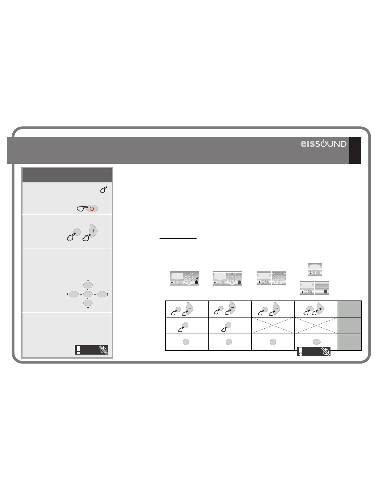
2.6.1. Three Access Levels
Certain keys have a cursor
function to scroll through different
menus. When a key is used as a
cursor, it will look like the cursor
symbols on the
face of the
Control Unit.
This indications is pictured when
access to a function requires that
the device be in a particular state
before any key is pressed (such
as “off”).
The appearance of this symbol
over a key is a prompt to
hold a key down for the time
specified.
In some cases it is necessary to
hold down two keys
simultaneously to
execute a
specified operation.
5’’
2.6. Program Menus
2
54
8
6
abc
jkl
ghi
tuv
mno
KEYS TO THE SYMBOLS
USED IN THIS MANUAL
instal
2’’
PRG
2’’
PRG
2’’
PRG
PRG PRG PRG
config
progr
2’’
m
m
2’’
PRG
2’’
PRG
2’’
PRG
19
control
unit OFF
control
unit OFF
42991
428A1
414A1/A2
422A1/A2
428A1/A4
42992
428A1
CC-1023ENG-10
Key Sequence Display Visual
The program menus are structured in level and sub-level menus.. The following
operations and keys in the menu will scroll the user between settings of the
list of options.
Once you select the desired setting, press the PRG key to store.
The entry will begin to flash quickly, indicating that the new setting has been
stored.
To delete an entry at any time, press the ZERO key for 1”
To exit a programming option without storing a setting, press the ON/OFF key.
When a setting to be programmed appears on the
display, it will be flashing, indicating it is ready to be
programmed.
If more than one setting is available (for example, days
of the week or digits of a date) use the +/- keys to scroll
forward/back.
The numeric keys can be used to change
a setting. In some cases, in addition
to the numeric keys, the +/- keys can also be used to
change settings
2.6.3. Menu Navigation
2.6.4. Quick Access To A Menu Option
As an alternative to scrolling through the menus to find an option, directly key in the option code followed by the menu access key (see code list in
2. Quick Reference Guide)
PRG
0
C
1’’
Pressing the 0 and 9 keys simultaneously blocks access to the programming and settings
menus.
To restore access to these menus, hold down the 0 and 9 keys.
2.6.2. Programming Permission
0
C
9
wxyz
0
C
9
wxyz
PGR
X
PGR
/
Scroll back to the previous
option within the same level.
Enter the level
Exit the level
Scroll forward to the next
option within the same level.
21
54
8
7
0
C
3
6
9
abc
jkl
ghi
pqrs
tuv
def
mno
wxyz
The following options are not available in 428A1, 428A4, 428A1+42992 models
20
428A1/A4
42992
428A1
CC-1023ENG-10
21
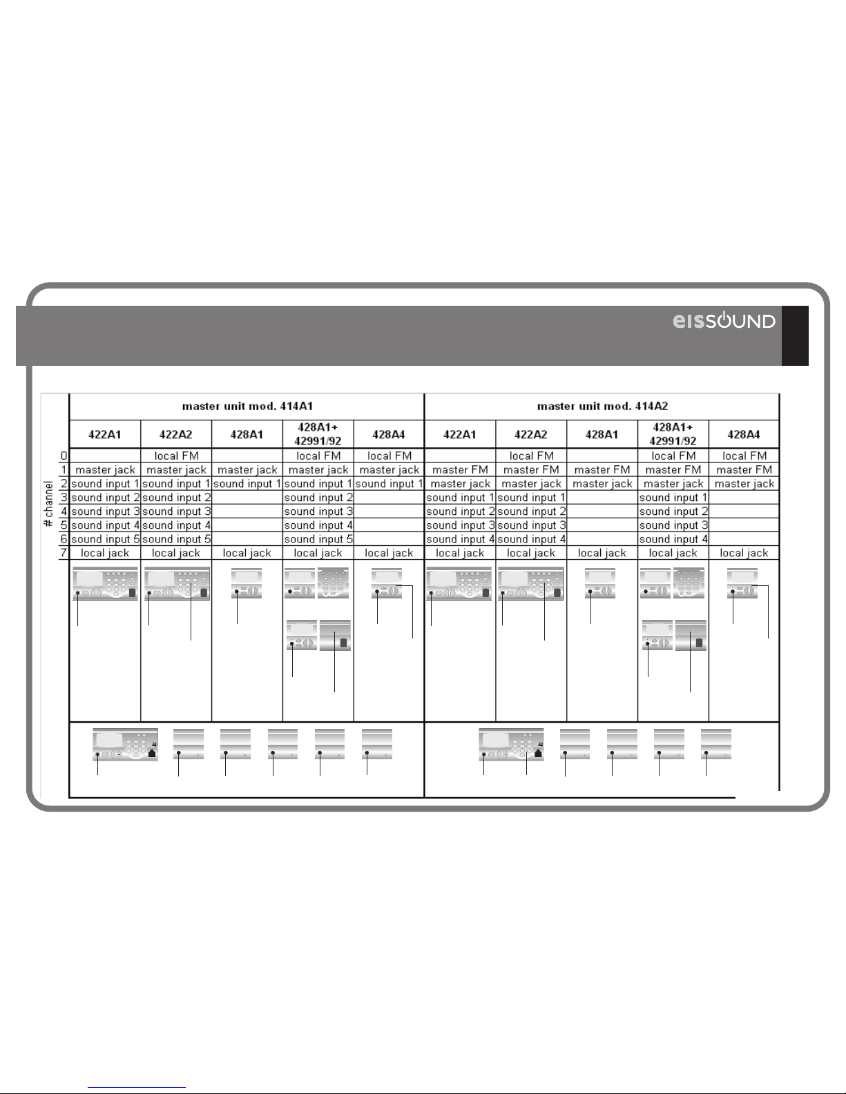
2.7. Music channels
42992
428A1
428A1 428A4
422A1 422A2
42991
428A1
channel 7 channel 7channel 7
channel 7
channel 7
channel 0
(FM)
channel 0
(FM)
channel 0
(FM)
42992
428A1
428A1 428A4
422A1 422A2
42991
428A1
channel 7 channel 7channel 7
channel 7
channel 7
channel 0
(FM)
channel 0
(FM)
channel 0
(FM)
414A1
41591/92 41591/9241591/92 41591/92 41591/92
channel 1 channel 2
channel 3
channel 4
channel 5
channel 6
414A2
41591/92 41591/9241591/92 41591/92
channel 2 channel 3
channel 4
channel 5
channel 6
channel 1
(FM)
CC-1023ENG-10

this page has been left intentionally in blank
CC-1023ENG-10

23
3. Central
CC-1023ENG-10
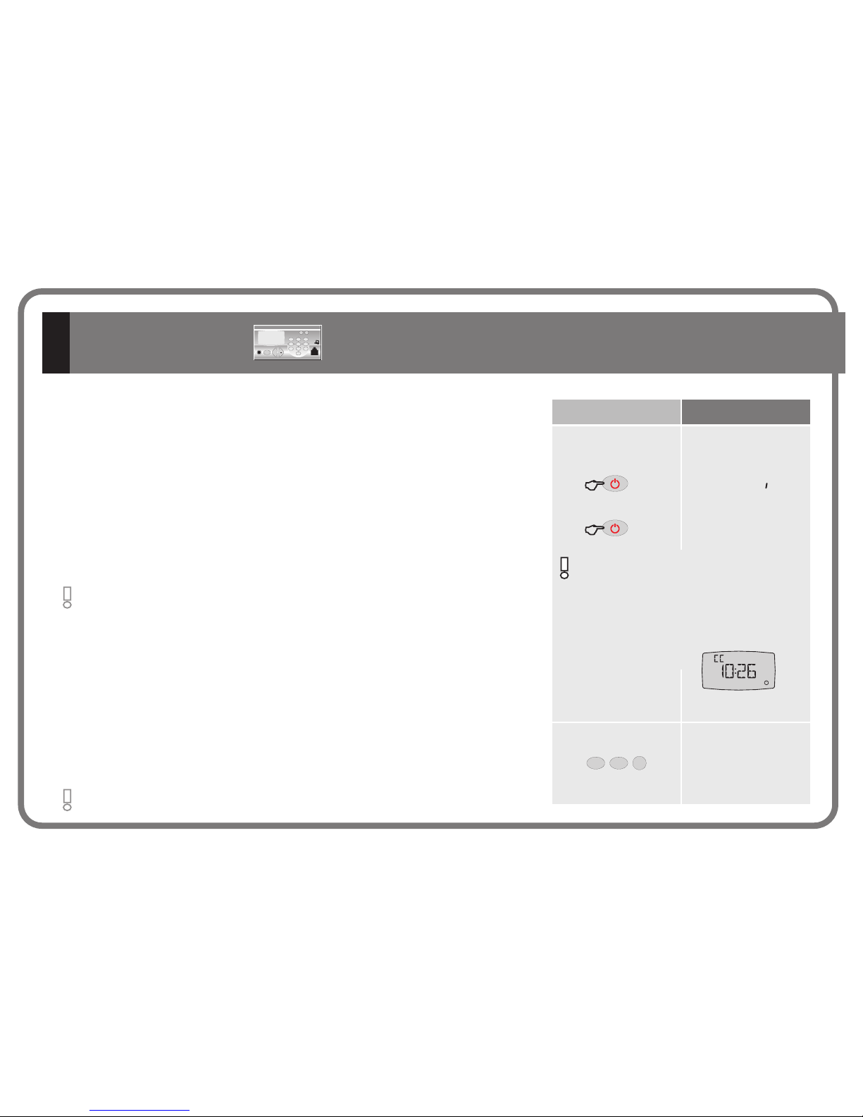
Key Sequence Display Visual
5’’
5’’
off
off
3.1.1.A. Manual System Off/On
3.1.1.B. Auto Switch On
This feature allows the user to program the Master Unit to automatically switch on the
system at a specific time. That is, at the time and days of the week defined by the user,
power will be fed to all Control Units. The Control Units switch on with the same settings
as at power off ( status, audio levels, music channel).
the program menu and selecting the status, time and days of the week to
program the function.
ON/OFF It is programmed accessing
ON/OFF
The master unit automatically performs
supervision and coordination tasks pertaining
to the operation of all the connected control
units. These tasks last brief periods of time
during which the keypad's response will be
slightly delayed.
3.1.1. Operation
The first time power is fed to the Master Unit, the Master Unit begins operating in off mode.
To switch off the whole system press for the time specified.
The ON/OFF status of all system Control Units is regulated from the Master Unit. To switch
on all the Control Units. press ON/OFF for the time specified. The Master Unit activates
power supply to the system. The Control Units start up with the same settings playing as
when last switched off.
ON/OFF The Master Unit
cancels power supply to the system. The Control Units store their current settings (ON/OFF
status, audio levels, active music channel).
on /
See 3.1.2.B.
1
PRG
2
abc
auto POWER ON
During these
operations the letters
CC will appear on
the display.
After a power loss: After a power loss, whether by disconnecting the
power supply or because of a power failure, the status of the system
once power is restored is the following: The Master Unit starts up with
the same settings as at power loss (off/on) and the Control Units start up
in their “ideal” state.
24
3.1. Master Unit
414A1/A2
CC-1023ENG-10
Key Sequence Display Visual
This feature allows the user to program the Master Unit to automatically switch off the system at
a specific time. That is, at the time and days of the week defined by the user, power will be shut
off from all Control Units. It also alerts the Control Units prior to switching off so that the
current settings are stored. Thus, the Control Units switch on with the same settings as at power
off (ON/OFF status, audio levels, music channel).
Access the program menu and select the ON/OFF status, time and days of the week to
program the function.
See 3.1.2.C.
1 1
3
def
PRG
3.1.1.C. Auto Switch Off
auto-power off
1 1
3
def
PRG
ON/OFF
power off
3
def
PRG
The quick function can also be used.
The function can only be activated or cleared from this
option in the program menu.
The function is activated when the icon is flashing.
The associated permission must be activated to execute this feature. See
3.1.3.E. Permission To Access General Standby
standby
PRG
7
pqrs
3.1.1.D. General Standby
The Master Unit (and any Control Unit) has the ability to make all the units connected to the
system go into standby mode ( music off). Use the quick function.
The Master Unit's FM tuner is user-friendly and intuitive and is exactly the same as for the FM tuner of Control Unit 422A2
Ver 4.1.2.D. Operation Of The Control Unit’s Local FM Tuner
Ver 4.1.2.E. Store Station Pre-sets Into The Local FM Tuner
See Program Menu: 3.1.2.D. FM Search Sensitivity - Master Unit
3.1.2.E. Deleting FM Tuning Pre-sets -Master Unit
3.1.2.F. Storing Station Frequencies Automatically
3.1.1.E. Operation of Master Unit FM Tuner (only 414A2)
25
CC-1023ENG-10
Key Sequence Display Visual
3.1.1.F. Telecontrol function
This feature allows the Master Unit to control the off/on status of the sound sources (apparatus) that supply the music channels. With this feature,
the apparatus only switch on when a Control Unit activates a music channel, that is using the apparatus.
The Control Units alert the Master Unit of a need for remote control, that is, that a Control Unit has
switched to a music channel that requires remote control. At that time the sound device that is
connected to the remote control base network feed (for example, a CD reader) immediately switches on.
At the same time, the Master Unit regularly monitors the remote control status. Thus, the remote control
ON/OFF function is carried out automatically, without direct user intervention.
When none of the Control Units are operating a music channel that requires remote control, the Master
Unit waits a few seconds and then disables the remote control. The sound device connected to the
Master Unit remote control feed switches off.
The telecontrol feature can be enabled and disabled using the function with quick access 6+PRG
NOTIF
PRG
4
ghi
3.1.1.G. Access To Intercom Calls Channel
A quick function can be used to manually make the intercom calls channel available if the
channel is busy when no intercom calls are taking place. This may be due to a problem in the
system. Any intercom call in progress is cut off at the time this function is activated.
The intercom calls channel (terminal #7) is the channel for conversation between the system’s Control Units. Because there can only be one active
conversation at a time, the Master Unit controls access to this channel to avoid mixing two or more concurrent conversations.
The microphone icon indicates that the intercom calls channel is busy.
An intercom call operation may not last for more than 3 minutes in total.
After three minutes, the Master Unit unilaterally cancels the operation.
26
channel
central 414A1
(without FM)
central 414A2
(with FM)
0 (local FM)
OFF OFF
1 ON OFF
2 ON ON
3 ON ON
4 ON ON
5 ON ON
6 ON ON
7 (discman)
OFF OFF
telecontrol
CC-1023ENG-10

Key Sequences
Display Visual
Key Sequences
Display Visual
8
tuv8tuv8tuv8tuv
1
0
C
5
jkl4ghi
1
0
C
5
jkl
5
jkl
5
jkl
PRG
1 1
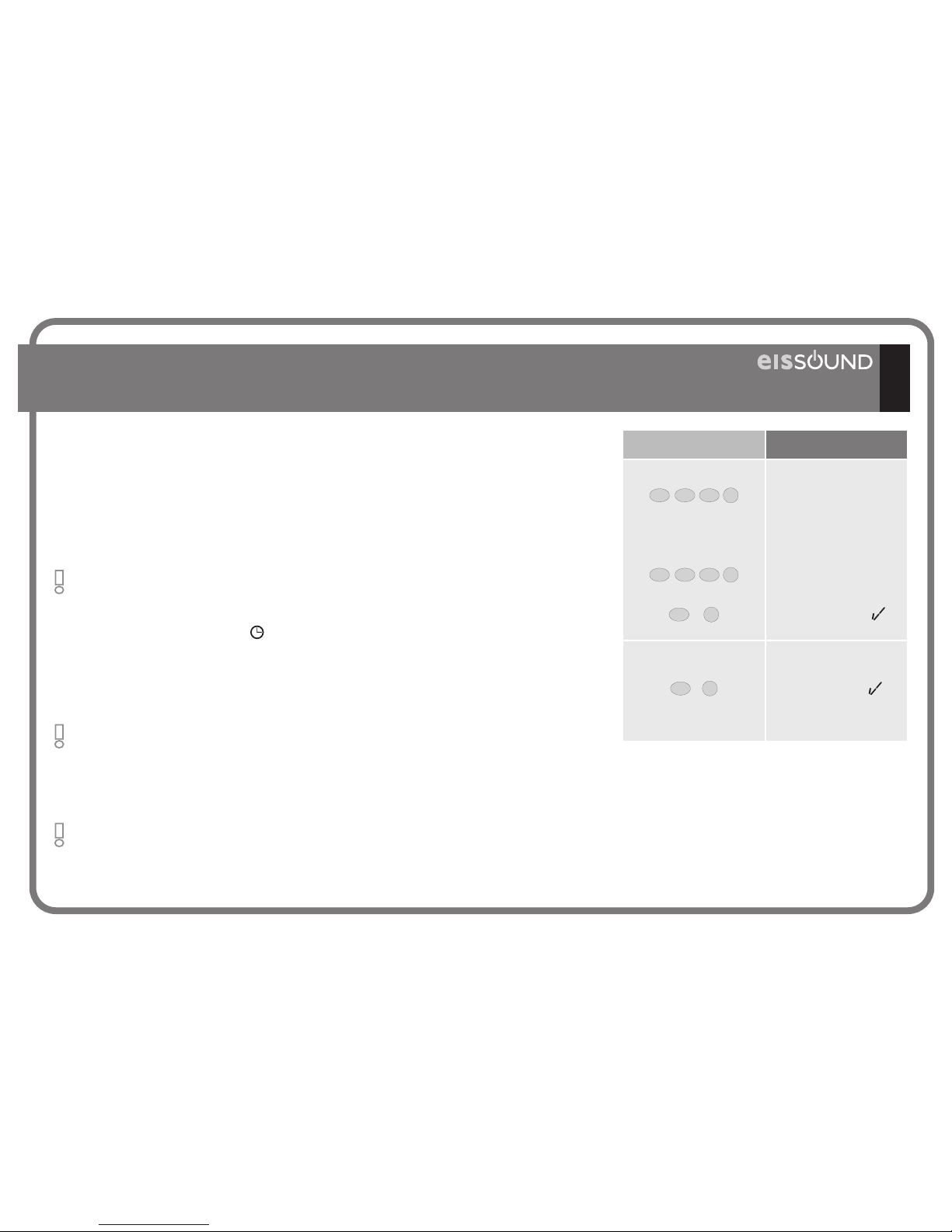
3.1.2. Program Menu
TIME-DATE
auto-power on
hh-mm
ON/OFF
13-43
off
10-54
on
hh-mm
ON/OFF
DATE
hh-mm
28-aUG-02
00-00
10-aUG-02
07-55
10-dEc-02
02
hh-mm
days
mo on
td on
10-dEc-04
5
jkl
5
jkl
5
jkl
5
jkl
PRG
1 2
abc
PRG
PRG
8
tuv
8
tuv
2
abc
3.1.2.A. Time and Date
3.1.2.B. Auto Power On
For programming
installation time and date
Enter
for example, to set 10:54
Store
Scroll to the next step
Enter
key in the 10th
Scroll to the month of
December
Scroll to set the year
Scroll to 2004
Store
PRG
PRG
8
tuv
2
abc2abc
5
jkl
5
jkl
0
C
7
pqrs
2
abc
su ON
su OFF
...
Store
PRG
The system’s time and date are shared by all connected units and can
be programmed at any given unit.
All other units will instantly be
updated accordingly.
The option to program a
time for the Master Unit to
switch on the power supply
at the time and days of the
week programmed.
For example, auto
power on at 07:55
every day of the week
except Saturdays and
Sundays.
27
CC-1023ENG-10
Key Sequences
Display Visual
0
C
5
jkl
7
pqrs
1
5
jkl
5
jkl
5
jkl
5
jkl
PRG
PRG
8
tuv
8
tuv
2
abc
PRG
1
3
def
auto-POWER OFF
ON/OFF
off
on
ON/OFF
hh-mm
00-00
17-50
hh-mm
dAYS
MO on
TD on
3.1.2.C. Auto Power Off
… CONTINUED
Key Sequences
Display Visual
2
abc
2
abc
SA OFF
SU ON
SU OFF
SA ON
PRG
Store
Key Sequences
Display Visual
2
abc
sens-4
sens-2
CENTRAL FM
sensiTIVITY
PRG
PRG
12
abc
3.1.2.D. FM Search Sensitivity - Master Unit (only 414A2)
Store
The option to program a time
for the Master Unit to switch off
the power supply at the time
and days of the week
programmed, switching off all
the Control Units.
For example, auto power
off at 17:50 every day of
the week except Saturdays
and Sundays.
The option to adjust the
automatic station search
sensitivity for the Master Unit
FM tuner.
To adjust the new
sensitivity;
4=max. 1=min.
28
CC-1023ENG-10
Key Sequences
Display Visual
Key Sequences
Display Visual
PRG
1
3
def
PRG
2
abc
3
def
PRG
PRG
2
abc
delete central fm
memory
off
on
PRG
2
abc2abc
3.1.2.E. Deleting FM Tuning Pre-sets -Master Unit
(only 414A2)
3.1.2.G. ON/OFF dimmer
Store
This option is only available in Master Unit models that
have an internal tuner. Permission for this option must be
activated in the Master Unit’s settings menu. See 3.1.3.D.
Permission to Store/Delete FM Tuning Pre-Sets - Master Unit
This option is only available in Master Unit models that
have an internal tuner. Permission for this option must be
activated in the Master Unit’s settings menu. See 3.1.3.D.
Permission to Store/Delete FM Tuning Pre-Sets - Master
Unit
o
3.1.2.F. Storing Station Frequencies Automatically (only 414A2)
Key Sequences
Display Visual
PRG
2
abc
off
AUTOSCAN
on
PRG
3
def
2
abc
The option to delete all the Master
Unit FM tuning pre-sets.
To confirm the command
to delete the data
To initiate the process
The Master Unit will store into memory the stations that are received with the highest quality, ordered from
lowest frequency (87.5 MHz) to highest frequency (108.0 MHz). The system will use all the memory slots
available, reaching the maximum of 20.
To confirm the command
To initiate the process
Enter code
Display window brightness for
Master Unit ON/OFF status is
programmed from these
options.
To adjust level
Light off
Light on
Lt 5
Lt 8
o
29
CC-1023ENG-10
 Loading...