


SWISS MADE
E1 & ES1 / ASSEMBLY INSTRUCTIONS
enjoy sports
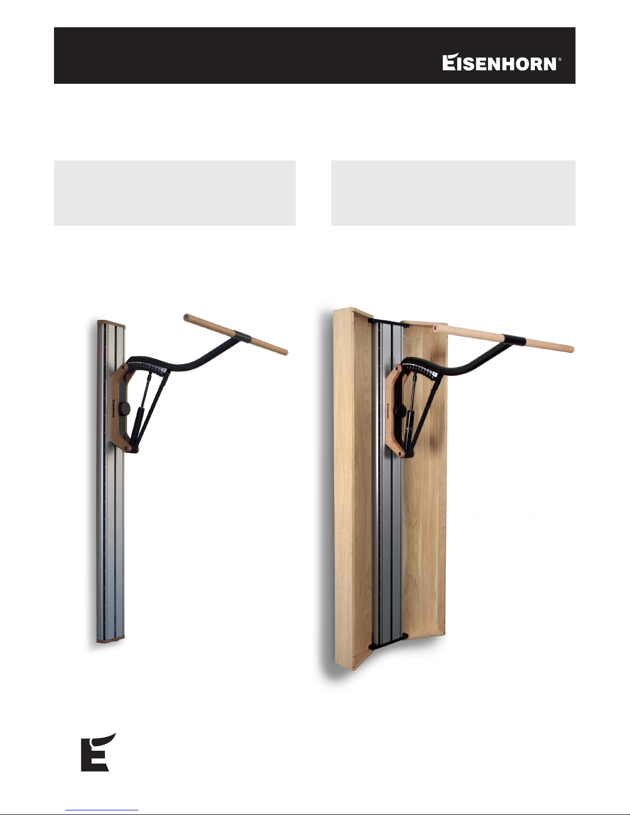
2 PRODUCT OVERVIEW
EISENHORN ES1EISENHORN E1
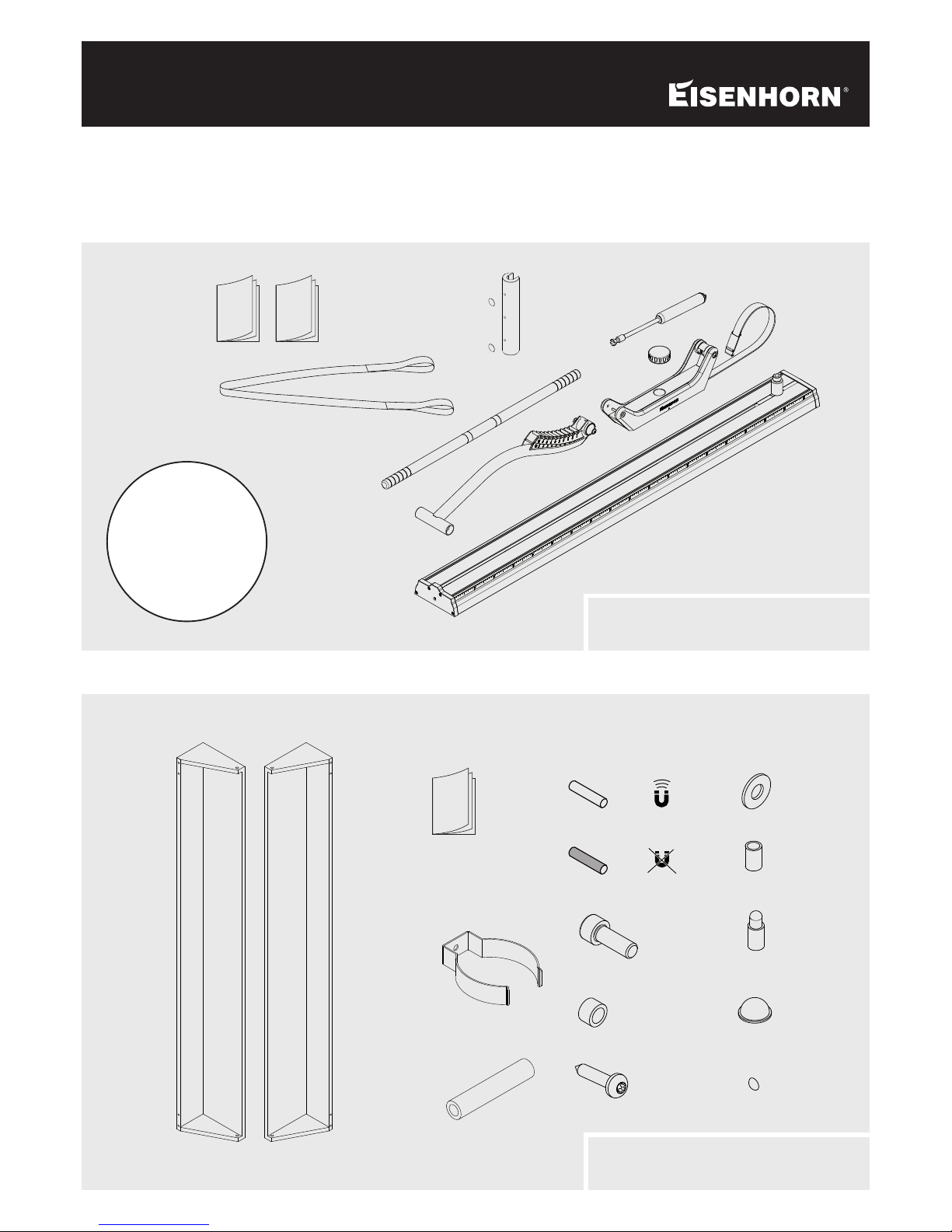
3 SCOPE OF DELIVERY
2x
2x
2x
6x
4x
4x
4x
3x
2x
2x
2x
1x
EISENHORN ES1
EISENHORN E1 & ES1
+
Screw set for wall
mounting
(see page 9)
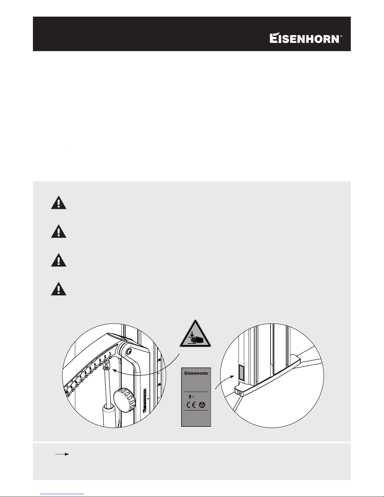
4 SAFETY INSTRUCTIONS
For setting up the device and the training itself, a separate user manual is
included in the delivery. Carefully read all the instructions for installation and
use, particularly those in the „SAFETY INSTRUCTIONS“ sections, before
starting the installation and using the device. Keep in mind that incorrect
installation or improper use may result in injury, and no liability or warranty
claims can be asserted.
Ensure that small children have no access to the installation materials. Swallowing small parts poses a choking hazard.
The piston is under high pressure and should not be exposed to temperatures
above 70 degrees. Select the installation location accordingly.
After installation, regularly check all screw connections to make sure they are
tight. See maintenance instructions.
Warning symbol and nameplate must be affixed as follows. If they are missing,
they must be re-ordered from EISENHORN and affixed to the device.
The device is built for indoor use (0 - 40 degrees Celsius and 30 - 75% humidity).
Trainingsgerät E1 / ES1
Seriennummer:
000 00051
Baujahr: 2015
100kg
EISENHORN AG
Rüttistrasse 49
CH-1716 Plaffeien
www.eisenhorn.com
5 IMPORTANT INFORMATION
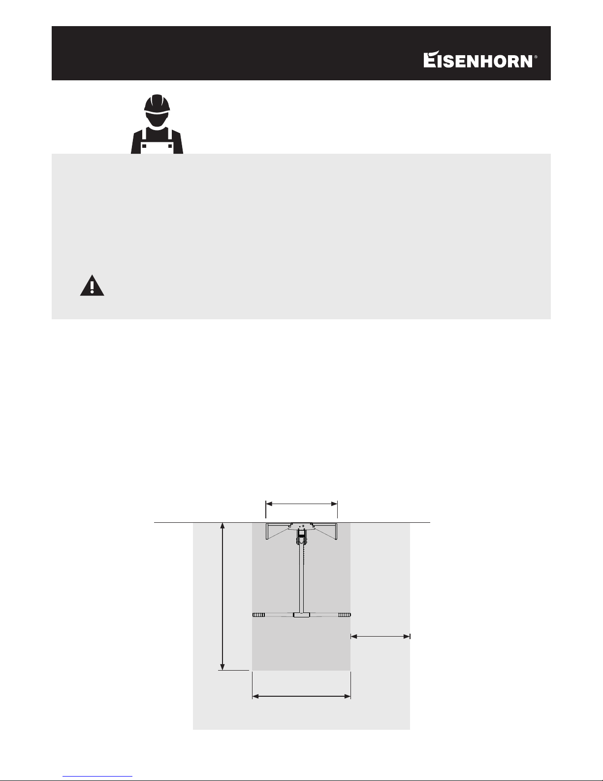
Choose the position on the wall so that you have enough room available later
for the different exercises. In particular, allow for sufficient distance to lamps,
light switches, electrical sockets, doorframes and window frames etc. for the
opened cabinet. For the main standard exercises, a minimum floor area of 1 x
1.5 m is sufficient. Ideally, there should be additional clearance of a good half
metre all around for optimal accessibility. A wall height of 2.12 m is sufficient
for mounting the device. For an unrestricted workout, a height of 2.25 m or
more is recommended.
A precondition for safe use of EISENHORN is a flat wall and professional wall
mounting. With the standard installation using 5 screws, each connection point
must withstand a tensile load of 800 Newtons. Screw and dowel materials must
be selected according to the wall (see page 9).
For the above reasons, we strongly recommend that you have the unit
installed by a competent professional.
1 m
0.73m
min. floor area
Ideal
clearance
0.5m
1,5 m
6 WALL MOUNTING
2
1
3
4
5
6
7
8
9
Mark the screw insertion points as per the dimensions on the drawing. Make
sure the holes are precisely vertical one above the other. If cavities, pipes, joints
between tiles or the like make it impossible to drill at this point, all holes except
the top one may be slightly offset in height (max. 5 cm).
After drilling, remove the drilling dust from each hole.
Now place the column against the wall. Distance between bottom edge and
floor is 21 cm.
Tip: Put the column on the packaging carton.
Start by mounting the third screw connection from the top.
Select the fastening components depending on the type of wall (see pages 9-14).
Mount the screw from the front through the groove in the column (see page 8).
Mount the two lower screw connections in the same way.
Make sure the sliding surfaces of the carriage and the front panel of the
column are clean.
Mount the carriage on the trolley, drag it down to half the column height and
attach it securely using the turning knob.
Now mount the top two screw connections.
Place the Eisenhorn in the corresponding bearing of the carriage and tighten the
two lateral screws with 15Nm torque.
Screw the piston into the rotary base of the carriage.
By rotating clockwise, align the clipper (e.g. using a screwdriver) parallel to the
locking pins.
Test whether the trolley can be moved along the whole length of the column
easily and without jamming. If the trolley jams at a particular point, the screw
connections in this area must be checked and adjusted (possibly screwed too
tight, or wall is uneven).

4
3
4
5
6
7
8
2
21cm
330
630
1680
1980
2070
7 WALL MOUNTING
9
1
Make sure the cylindrical surfaces of the clipper and the 10 pins for the
resistance levels are always clean. Otherwise, paintwork defects or noise
(squeaking) may occur due to the high loading pressure.

8 IMPORTANT INFORMATION
TIGHTENING THE SCREWS
Mount the screw from the front through the groove in the column into the
mounting bracket and screw it tight until the bracket deforms slightly.
PLEASE NOTE: Do not screw too tight. The bracket should not bend all the
way to the wall!
Right!Wrong!
Column Column
Wall Wall

9 SCREW SET FOR WALL MOUNTING
SCREW MATERIALS
It must be determined at the installation spot whether the screw material provided is suitable for the selected wall.
EISENHORN offers no guarantee for the use of unsuitable mounting parts or
installation not undertaken by a professional.
Bore diameter 8mm
5x
2
5x
1
Diameter 6mm x 85mm
5x
4
Bore diameter 10mm
5x
Diameter 8mm x 80mm
3

10 INSTALLATION MATERIALS
SOLID WOOD MOUNTING:
It must be determined at the installation spot whether the screw material provided is suitable for the selected wall.
EISENHORN offers no guarantee for the use of unsuitable mounting parts or
installation not undertaken by a professional.
Tighten the screws as per the information on page 8.
1

11 INSTALLATION MATERIALS
DRYWALL POSTS MOUNTING:
It must be determined at the installation spot whether the screw material provided is suitable for the selected wall.
EISENHORN offers no guarantee for the use of unsuitable mounting parts or
installation not undertaken by a professional.
Tighten the screws as per the information on page 8.
1

12 INSTALLATION MATERIALS
4
DRYWALL (GYPSUM FIBREBOARD) MOUNTING:
It must be determined at the installation spot whether the screw material provided is suitable for the selected wall.
EISENHORN offers no guarantee for the use of unsuitable mounting parts or
installation not undertaken by a professional.
Tighten the screws as per the information on page 8.
PLEASE NOTE!
The carrying capacity of
drywalls can vary greatly.
Ensure the recommended
tensile load per point of
connection can be borne
(see page 5).
If possible, choose the
installation method as per
page 11.
3

13 INSTALLATION MATERIALS
CONCRETE / MASONRY MOUNTING
It must be determined at the installation spot whether the screw material provided is suitable for the selected wall.
EISENHORN offers no guarantee for the use of unsuitable mounting parts or
installation not undertaken by a professional.
Tighten the screws as per the information on page 8.
PLEASE NOTE!
After drilling, thoroughly
remove the drilling dust
from each hole. Otherwise
an excessively high screwin force results, which can
lead to shearing-off of the
screw.
2
1
Borehole depth
min. 90mm

14 INSTALLATION MATERIALS
PERFORATED BRICK MOUNTING
It must be determined at the installation spot whether the screw material provided
is suitable for the selected wall. Drilling must not be done with a power tool.
EISENHORN offers no guarantee for the use of unsuitable mounting parts or
installation not undertaken by a professional.
Tighten the screws as per the information on page 8.
2
1

15 ASSEMBLING THE CABINET DOORS (ES1)
ES1 DESIGNER CABINET
If you have purchased an EISENHORN ES1 with designer cabinet, now proceed
with the assembly of the cabinet doors. A separate installation manual is
included with the delivery of the designer cabinet.
The following pages describe how to mount the cabinet doors on the column.

16 MOUNTING THE CABINET DOORS (ES1)
2x
2x 2x
Magnetic
2x
1x
2x
1 2
3

17 MOUNTING THE CABINET DOORS (ES1)
4x
4x
Firmly stick on the rubber pads as shown above.

18 MOUNTING THE CABINET DOORS (ES1)
4x
4x
2x
(top only)
1
1
2
3
2
3
undertake
on both sides
TOP
TOP
BOTTOM

19 MOUNTING THE BLOCKER BRACKET
E1 ES1
90mm
Firmly stick on the metal disks as shown above.

As manufacturer we declare that the training device specified below complies with the directives and standards given below.
Manufacturer: EISENHORN AG, CH-1716 Plaffeien / Authorised representative for the technical documents: EISENHORN AG, Michael
Schrag, CH-1716 Plaffeien / Name of the equipment, trade name: Training device / Model, type: E1/ES1 / Serial number: E1/ES1 xxx xxxxx /
Directives: 2006/42/EC (09.06.2006) Machinery Directive of the European Parliament and of the Council / Standards: EN ISO 20957-1:2013
Stationary Training Equipment – Part 1: General safety requirements and test methods (ISO 20957-1:2013); German version EN ISO 20957-1:2013
Plaffeien, 31.03.2016 / Michael Schrag, Managing Director …………….....……
www.eisenhorn.com Issue status: March 2016
 Loading...