

Eisele AT 44F, AT 54F, AT 84O, AT 74O, AT 104O Operation Manual
...
Submersible Motor Pump
AT 44F – 304S
Operation Manual
Technical modifications reserved Status: 22. Jan. 2019
Serial number: _________________

Franz Eisele u. Söhne GmbH & Co. KG
Page 2 of 41
Contact
Franz Eisele u. Söhne GmbH & Co. KG
Pumpen und Maschinenfabrik
Hauptstraße. 2 - 4
72488 Sigmaringen - Laiz
Tel: +49 (0) 07571 / 109 - 0
Fax: +49 (0) 07571 / 109 - 88
E-Mail: info@eisele.de
www.eisele.de

Franz Eisele u. Söhne GmbH & Co. KG
Page 3 of 41
Table of Contents
1 FOREWORD ................................................................................................................................... 5
1.1 INFORMATION ABOUT THE MANUAL ............................................................................................. 5
1.2 CUSTOMER SERVICE ................................................................................................................. 5
1.3 SAFEKEEPING............................................................................................................................ 5
1.4 SCOPE OF SUPPLY .................................................................................................................... 5
2 SAFETY .......................................................................................................................................... 6
2.1 USER'S DUTY OF CARE .............................................................................................................. 6
2.2 BASIC SAFETY INSTRUCTIONS .................................................................................................... 6
2.3 EXPLANATION OF THE SAFETY SYMBOLS USED ........................................................................... 7
2.4 GENERAL SAFETY REGULATIONS: .............................................................................................. 8
2.5 EMPLOYEE QUALIFICATION ........................................................................................................ 9
2.6 RISK OF INJURY ....................................................................................................................... 10
2.7 PRODUCT LIABILITY ................................................................................................................. 10
3 PRODUCT DESCRIPTION ........................................................................................................... 11
3.1 PROPER INTENDED USE ........................................................................................................... 11
3.2 FORESEEABLE MISUSE ............................................................................................................ 12
3.3 STRUCTURE ............................................................................................................................ 12
3.4 TECHNICAL DATA ..................................................................................................................... 13
3.5 MODIFICATION TO THE PRODUCT .............................................................................................. 14
3.6 ELECTRICAL PROTECTION AND MONITORING EQUIPMENT .......................................................... 14
3.7 RATING PLATE......................................................................................................................... 15
3.8 WIRING DIAGRAM .................................................................................................................... 16
4 TRANSPORT AND BEARING ..................................................................................................... 18
4.1 SPECIAL PERSONNEL QUALIFICATION FOR THE TRANSPORT ...................................................... 18
4.2 ADMISSIBLE DEVICES AND AUXILIARY EQUIPMENT FOR THE TRANSPORT .................................... 18
4.3 TRANSPORT ............................................................................................................................ 18
4.4 STORAGE CONDITIONS ............................................................................................................ 19
5 INSTALLATION ............................................................................................................................ 20
5.1 SPECIAL PERSONNEL QUALIFICATION FOR THE INSTALLATION .................................................... 21
5.2 CUSTOMER-SIDE PREREQUISITES FOR THE INSTALLATION ......................................................... 21
5.3 SAFETY INSTRUCTIONS FOR THE INSTALLATION ......................................................................... 21
5.4 SPECIAL HAZARDS DURING INSTALLATION ................................................................................. 22
5.5 ELECTRICAL CONNECTIONS ..................................................................................................... 23
5.6 INSTALLATION NOTES .............................................................................................................. 24
5.7 INSTALLATION INSTRUCTIONS ................................................................................................... 24
5.8 DESIGN ................................................................................................................................... 24
5.9 DISPOSAL OF INSTALLATION MATERIAL ..................................................................................... 24
5.10 AFTER INSTALLATION IS COMPLETED ........................................................................................ 24
6 COMMISSIONING ........................................................................................................................ 25
6.1 SAFETY INSTRUCTIONS ............................................................................................................ 25
6.2 PRECONDITIONS ...................................................................................................................... 26
6.3 PROCEDURE ........................................................................................................................... 26
7 OPERATION ................................................................................................................................. 27
7.1 PERSONNEL QUALIFICATION..................................................................................................... 27
7.2 NORMAL OPERATION ............................................................................................................... 27
7.3 PERFORM THE FOLLOWING INSPECTIONS BEFORE EACH START: ................................................. 28
7.4 OPTIMAL PUMPING .................................................................................................................. 28

Franz Eisele u. Söhne GmbH & Co. KG
Page 4 of 41
8 FAULT ........................................................................................................................................... 29
8.1 FAULT CAUSES ........................................................................................................................ 29
8.2 PERSONNEL QUALIFICATION..................................................................................................... 30
8.3 SAFETY INSTRUCTIONS FOR THE RECTIFICATION OF FAULTS ...................................................... 30
9 INSPECTION AND MAINTENANCE ............................................................................................ 31
9.1 MAINTENANCE WORK .............................................................................................................. 32
9.2 WEAR ..................................................................................................................................... 32
9.3 CLEANING ............................................................................................................................... 32
9.4 OIL INSPECTION AND CHECK OIL LEVEL .................................................................................... 32
9.5 OIL CHANGE............................................................................................................................ 33
9.6 MECHANICAL SEALS ................................................................................................................ 34
9.7 ELECTRICAL COMPONENT ........................................................................................................ 34
9.8 CABLE WINCH AND FASTENING CABLE...................................................................................... 34
9.9 REPLACING THE PROPELLER BLADE (TYPE S) / IMPELLER ......................................................... 35
9.10 MAINTENANCE PLAN ................................................................................................................ 36
9.11 INSPECTION ............................................................................................................................. 37
9.12 MISCELLANEOUS ..................................................................................................................... 37
10 REMOVAL ................................................................................................................................ 38
10.1 BEFORE REMOVAL ................................................................................................................... 38
10.2 DANGERS DURING THE REMOVAL ............................................................................................. 38
10.3 REMOVAL OF THE SUBMERSIBLE MOTOR PUMP .......................................................................... 39
10.4 DISPOSAL ............................................................................................................................... 39
11 ANNEX ...................................................................................................................................... 40
11.1 ABBREVIATIONS ....................................................................................................................... 40
11.2 REPLACEMENT PARTS LIST ...................................................................................................... 40

Franz Eisele u. Söhne GmbH & Co. KG
Page 5 of 41
1 Foreword
1.1 Information about the Manual
This manual contains information for the transport, installation, maintenance and removal of the
submersible motor pump. The safety instructions are to be observed, in order to ensure safe operation.
We reserve the right to make changes to the illustrations and data specified in this manual, for the
purpose of further development.
Reprinting, translation and duplication in any form, even in extracts, requires the written consent of the
manufacturer.
Abbreviations, units, specialist terms, special designations or terminology common in the branch, that
are used in this manual, are explained in more detail in the chapter entitled “Annex”.
This manual is a component part of the scope of supply.
• This manual is not subject to any revision service. The respective latest version can be obtained
via specialist shops or directly from the manufacturer.
• It has a modular structure and relates exclusively to the specified product. Further information
about the product and the components associated with it can, if necessary, be taken from the
relevant documents or instructions. This applies in particular for safety instructions!
1.2 Customer Service
In case of need, please contact the authorised specialist dealer.
An extensive dealer search is available on our homepage in the Internet at the following address:
National:
• https://www.eisele.de/nc/vertriebspartner/national/
International:
• https://www.eisele.de/vertriebspartner/international/
1.3 Safekeeping
Keep the operation manual (including the relevant associated documents) ready at hand close to the
submersible motor pump.
1.4 Scope of Supply
The scope of supply is to be checked for completeness and damage with the help of the enclosed
packing list. It is possible that the scope of supply deviates from the illustration on the title page. The
operation manual is only intended for the respective submersible motor pump. For accessories,
a separate operation manual must be requested.

Franz Eisele u. Söhne GmbH & Co. KG
Page 6 of 41
2 Safety
2.1 User's Duty of Care
We point out, that the commissioning is prohibited, until it has been
established, that the machine/system in which this product is installed,
complies with the provisions of the underlying directives.
The product has been designed and manufactured under consideration of a risk analysis and after
careful selection of the harmonised standards to be observed, as well as other technical specifications.
Consequently a maximum level of safety is ensured.
This safety can however only be achieved in practical operation, when all measures necessary for this
are taken. It falls within the duty of care of the user, to plan these measures and to check their
implementation.
The user must ensure that
• All persons who perform work or activities in connection with the product, have carefully read
and understood the manual (in particular the safety instructions and warnings).
• The manual is always available in a legible condition and complete at the place where the
product is used.
• All persons who perform activities on the product can examine the manual at any time.
• The statutory regulations are observed.
• For the operation, special operating instructions coordinated to the circumstances of his
business are prepared, which once again explicitly take into consideration the safety aspects.
• The product is only used as intended.
• The product is only operated in a perfect, functional condition. In particular the safety equipment
must be checked regularly for functionality.
• The work to be carried out is only executed or performed by an adequately qualified person!
• Personnel are regularly instructed in all applicable matters of work safety and environmental
protection, and know the manual and in particular the safety instructions contained in it.
• Trainee operating personnel work with the product exclusively under the supervision of an
experienced person.
• Safety symbols, signs and stickers that are attached to the product are immediately replaced
with original ones if they become illegible or are lost!
• In the direct vicinity of the submersible motor pump, if necessary a warning sign is erected with
the inscription “Attention! Toxic Fumes!”.
• Rescue routes are marked by signs according to national conventions!
• Necessary personal protective equipment for the operating, maintenance and repair personnel
are available and used.
• Unauthorised persons (for example children) do not stand in the danger zone.
2.2 Basic Safety Instructions
Safety instructions serve the avoidance of personal injury and damage to the submersible motor pump
as well as the environment. All operators are obligated to read and always observe these safety
instructions. It is important, that this instruction is read carefully by the user and the operating personnel.

Franz Eisele u. Söhne GmbH & Co. KG
Page 7 of 41
2.3 Explanation of the Safety Symbols Used
Safety symbols draw attention to the importance of the adjacent texts.
The design of the warning signs is based on DIN ISO 3864.
Notes about Signs and Symbols
Background
colour of the field
Contrast
colour
Meaning/ Use
Illustration
of the field for
specification of
the level of danger
Red
White
Danger!
Warns of an imminent danger that
leads to death or serious injuries, if
not avoided.
Orange
Black
Warning!
Warns of a potentially hazardous
situation that leads to death or
serious injuries, if not avoided.
Yellow
Black
Caution!
Warns of a potentially hazardous
situation that leads to moderately
severe or minor injuries, if not
avoided.
White
Black
Note!
Warns of a potentially hazardous
situation that leads to material or
environmental damage, if not
avoided.

Franz Eisele u. Söhne GmbH & Co. KG
Page 8 of 41
2.4 General Safety Regulations:
Overriding Provisions
• Ensure that the operating personnel is at least 18 years old.
• Ensure that the operating personnel and the pump are not in potentially explosive atmospheres.
• Ensure that the operating personnel are regularly instructed in all applicable matters of work
safety and environmental protection.
• Make sure that the operating personnel has read and observes the operation manual.
• Make sure that the warning and notice signs are attached and legible.
• Observe all warning and notice signs attached to the submersible motor pump.
• Use personal protective equipment, including safety shoes, fall protection, protective gloves,
gas detector, respirator etc.
• Make sure that the submersible motor pump is not put into operation without the safety
equipment and guards attached by the manufacturer or installed on site.
• Have defects on the submersible motor pump repaired immediately.
To maintain the Safety and Function,
• Defective components must be replaced exclusively by original replacement parts with identical
electrical and mechanical data.
• All safety equipment, fastenings as well as electrical connections and lines must be inspected
regularly for perfect condition.
• Defects on the submersible motor pump must be repaired immediately.
• Submersible motor pump and associated peripherals must not be modified or converted,
otherwise the operation manual will expire and the declaration of conformity will be invalidated.
Before working on electrical equipment the following points are to be observed:
• Completely disconnect the electric motor and control circuits from all current and voltage.
• Secure electric motor against restarting.
• Verify zero voltage with appropriate measuring device.
• Ground and short circuit the electric motor.
• Cover or cordon off live parts.
• Attach a warning sign.
If the work is not performed by Eisele
• Ensure that all work is performed and accepted exclusively by persons who have been trained,
instructed or authorised by Eisele or by specialists.
• Make sure that the trained specialist issues a written confirmation or marks the machine with
his test mark.
Danger due to potentially explosive, toxic and combustible atmospheres
It is possible that toxic, combustible and potentially explosive gases escape from the pump medium.
The following points are therefore to be observed without fail:
• Make sure that installation and maintenance work is performed exclusively by trained
specialists. The Industrial Safety Regulations (BetrSichV) as well as the safety and
maintenance instructions in the operation manual are thereby to be strictly observed.
• Make sure that there is no potentially explosive atmosphere present during operation as well
as installation and maintenance work on tank openings and couplings.
• Have work that influences the explosion protection performed exclusively by trained specialists.

Franz Eisele u. Söhne GmbH & Co. KG
Page 9 of 41
Increased risk of explosion in biogas tanks
• It is possible, when opening or removing the submersible motor pump, that gases escape,
which can form potentially explosive mixtures in combination with air.
• Keep all source of ignition (e.g. naked flame, hot heat sources, mobile phones, tools that are
not non-sparking, electrical appliances not protected against explosion) away from the
potentially explosive area (Ex-Zone).
• Use exclusively non-sparking tools.
• Make sure that the tool used (e.g. drilling machine, drill, core drill, chisel etc.) is a special non-
sparking tool.
• Make sure that welding, flame-cutting and spark generating work is not performed inside an
Ex-Zone.
• Ensure that all work, in particular welding, flame-cutting and spark generating work, is carried
out outside the potentially explosive area.
Risks of environmental damage
• Make sure that neither gearbox oil nor lubricant flows into the ground, water or sewage system.
• Dispose of lubricant residues, old oil and containers and rags contaminated with it in
accordance with regulations.
• After decommissioning, clean and dispose of the submersible motor pump in accordance with
national and regional statutory regulations.
2.5 Employee Qualification
Operating Personnel:
The personnel for the installation, commissioning, operation, maintenance, cleaning, repair and
inspection of machines must have the necessary qualifications. Personnel under the influence of
alcohol, drugs or medicines must not transport, install, start-up, operate or repair the submersible motor
pump.
Trained / Instructed Personnel:
Persons, who have been instructed and, if necessary, trained in the tasks to which they have been
assigned and the possible risks thereby occurring with improper behaviour. They have also been
instructed about the necessary protective equipment and protective measures.
• Personnel undergoing training, apprentices and those being instructed or those in general
education may only be active under the constant supervision of an experienced person.
Specialist:
Persons who, based on their professional education, knowledge and experience, can assess the work
to which they are assigned and recognise possible hazards. Furthermore, they have knowledge of the
relevant regulations.
In addition to this, special qualifications are required for the following activities:
• Transport
• Cleaning
• Installation
• Commissioning
• Operation
• Maintenance/ Servicing
• Troubleshooting

Franz Eisele u. Söhne GmbH & Co. KG
Page 10 of 41
• Repairs
• Decommissioning
2.6 Risk of Injury
To avoid injuries:
• Observe the accident prevention regulations of the Industrial Safety Ordinance (BetrSichV).
• Observe the accident prevention regulations for agricultural biogas installations.
• Observe all rules of engineering.
• Observe all safety instructions.
• Provide and observe national and regional regulations for the prevention of accidents, industrial
safety.
• Provide and observe national and regional hygiene regulations. Contact with liquid manure,
sewage, etc. can trigger serious infections.
• Provide and observe the rules for environmental protection.
• Make sure, that persons under the influence of alcohol, drugs or medicines do not transport,
install, start up, operate or repair the submersible motor pump.
• Observe all warning and notice signs attached to the submersible motor pump.
2.7 Product Liability
Modifications to the submersible motor pump and associated peripherals may only be performed
following consultation with and written approval of Eisele. Original replacement parts and accessories,
approved by Eisele, are a mandatory condition for the warranty. The use of other parts will invalidate
the warranty claim.
The company Franz Eisele & Söhne GmbH & Co. KG accepts no liability for personal injury, damage
to material or the environment and/or business losses resulting from the fact, that the operation manual
has not or not completely been observed. The warranty shall expire in the case of unauthorised
interventions. Warranty and liability claims for personal injury, material and environmental damage are
excluded, if they can be traced back to one of more of the following causes:
• Non-observance of the instructions in the operation manual concerning installation, removal,
commissioning, operation and maintenance.
• Improper use.
• Improper transport, installation, removal, commissioning, operation or repair.
• Unauthorised structural modifications to the submersible motor pump.
• Improperly performed repair.
• The effect of foreign objects that are not suitable for the process.
• Defective monitoring of wearing parts.
For details about the warranty, please refer to our General Delivery Conditions or your contract
documentation.
Franz Eisele u. Söhne GmbH & Co. KG
Page 11 of 41
3 Product Description
Risk of death from explosions!
• Operation of the submersible motor pump in an Ex-Zone is not
permitted.
• If, due to the installation situation, there is an Ex-Zone above the
substrate, it must be ensured by means of suitable safety
equipment, that if the submersible mixer pump surfaces it is fully and
completely disconnected from voltage and current.
3.1 Proper Intended Use
The submersible motor pump is primarily intended for use in agricultural operations, in biogas
installations and in industry and is used in this environment for pumping sewage, sewage sludge and
liquid manure with a limited viscosity and with a limited proportion of fibrous material.
The pumping of other media is only possible after consultation with and written authorisation by Eisele.
All types of use not listed here are not as intended and are therefore regarded as improper use!
We draw your attention to the fact, that operation of the submersible motor pump outside the described
scope of use is forbidden. The manufacturer/supplier is not liable for damage resulting therefrom. The
risk is borne solely by the user.
Proper intended use also includes the observance of the operation manual and the inspection and
maintenance conditions.
• The manufacturer points out explicitly, that only original parts and accessories are coordinated
to the product, tested and approved.
• The installation or use of third-party products can negatively influence the specified
characteristics of the original parts and lead to danger for people, the environment and animals.
• Any liability of the manufacturer is excluded for injury/damage to humans, animals,
environment, machines and installations, that results from the use of third-party products.
• For reasons of safety, no unauthorised modifications may be undertaken! All planned
modifications must be authorised in writing by the manufacturer.
• Ensure, after installation or assembly with other components, that the conformity of the end
product is guaranteed in accordance with the applicable directive.
• Sufficiently dimensioned attachment of the submersible motor pump.
• Ensure that the medium is flowable and homogeneous.
• The pumping capacity and limits of use of the pump are dependent on the viscosity. If this data
is not available for the pump medium, as a guide value a maximum dry matter content (TS) of
10% can be used for liquid manure.
• Make sure that the pH-value of the medium to be pumped is between 6.5 and 7.8.
• Make sure that all safety and monitoring equipment e.g. pressure-relief valves, pressure
transducer and/or thermal sensor of the electric motor, are connected and fully functional.
• Maintain inspection and maintenance intervals.
• Observe operating instructions, safety, rule, prohibitory and warning notices.
• For a change of the installation location or the operating situation of the submersible motor
pump, pay attention to possible Ex-Zones.
• All medium conducting components in the piping system must be designed for the maximum
pressure of the pump.
Franz Eisele u. Söhne GmbH & Co. KG
Page 12 of 41
3.2 Foreseeable Misuse
Not as intended is the use of the submersible motor pump in an Ex-Zone.
Any use other than that described in chapter 3.1 is not as intended. The user or the operator of the
submersible motor pump is responsible for all damage that does not result through proper intended
use.
To ensure safe operation and avoid damage to the submersible motor pump it is to be ensured, that
the pump medium does not contain the following materials, foreign matter or foreign objects:
• Slaughterhouse waste (bones, etc.)
• Bulky, sharp-edged solids (square timber, boards, tree branches, etc.)
• Metallic and non-metallic parts (such as e.g. screws, iron bars, steel wire, chains, etc.)
• Long-fibred and other products that form a blockage (cords, foils, etc.)
Furthermore it is to be ensured without fail, that the piping system is consistent for the pump medium.
Otherwise sudden excessively high pressures and possible damage can occur.
To avoid cavitation and operational disturbances, ensure adequate flowability of the pump medium.
The higher the dry-matter content, the greater the wear and the probability of the occurrence of
operational disturbances.
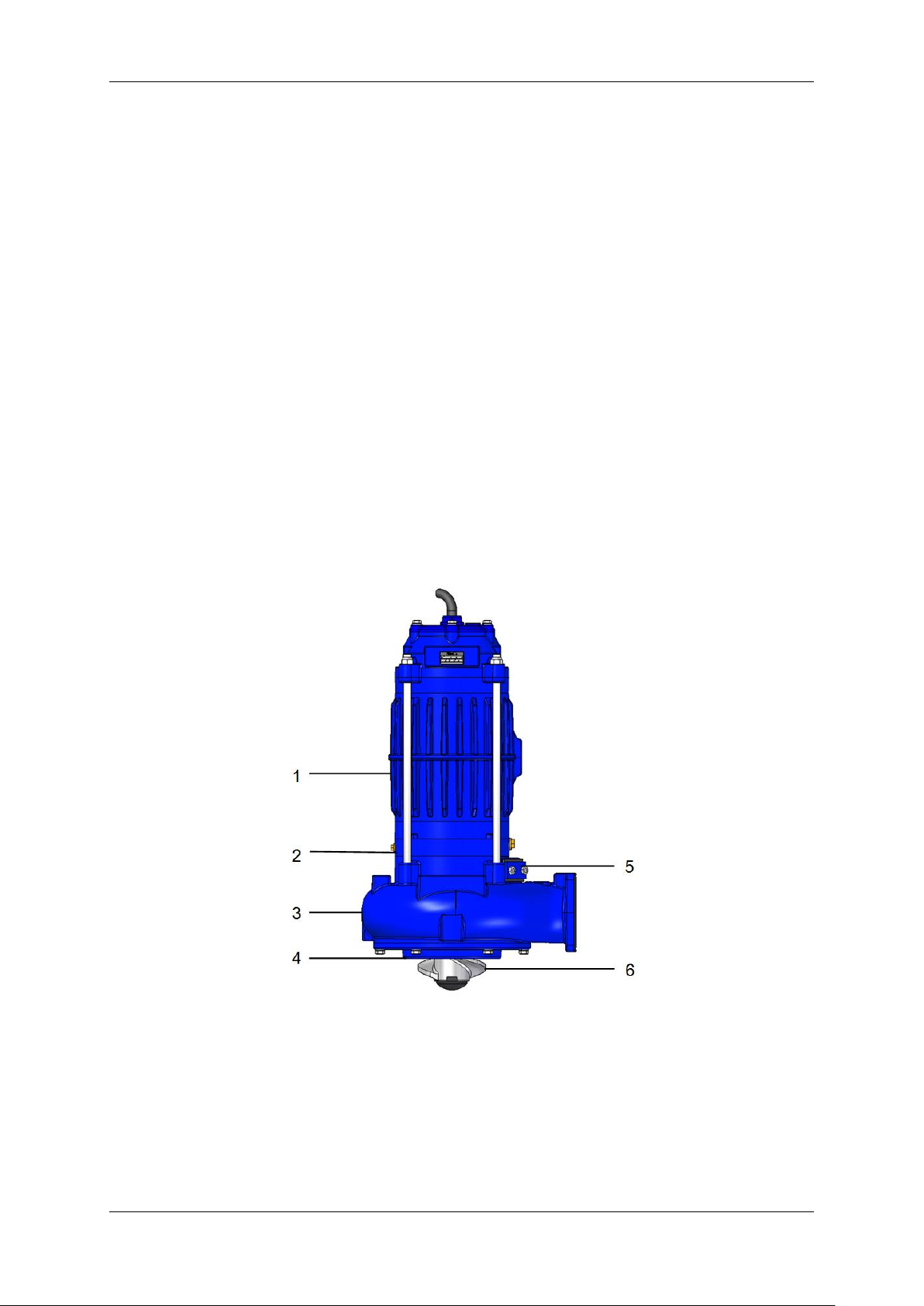
3.3 Structure
The illustration does not always correspond with the scope of supply!
1. Submersible motor
4. Inlet nozzle
2. Oil chamber
5. Gas escape hole
3. Pump housing
6. Propeller blade
Franz Eisele u. Söhne GmbH & Co. KG
Page 13 of 41
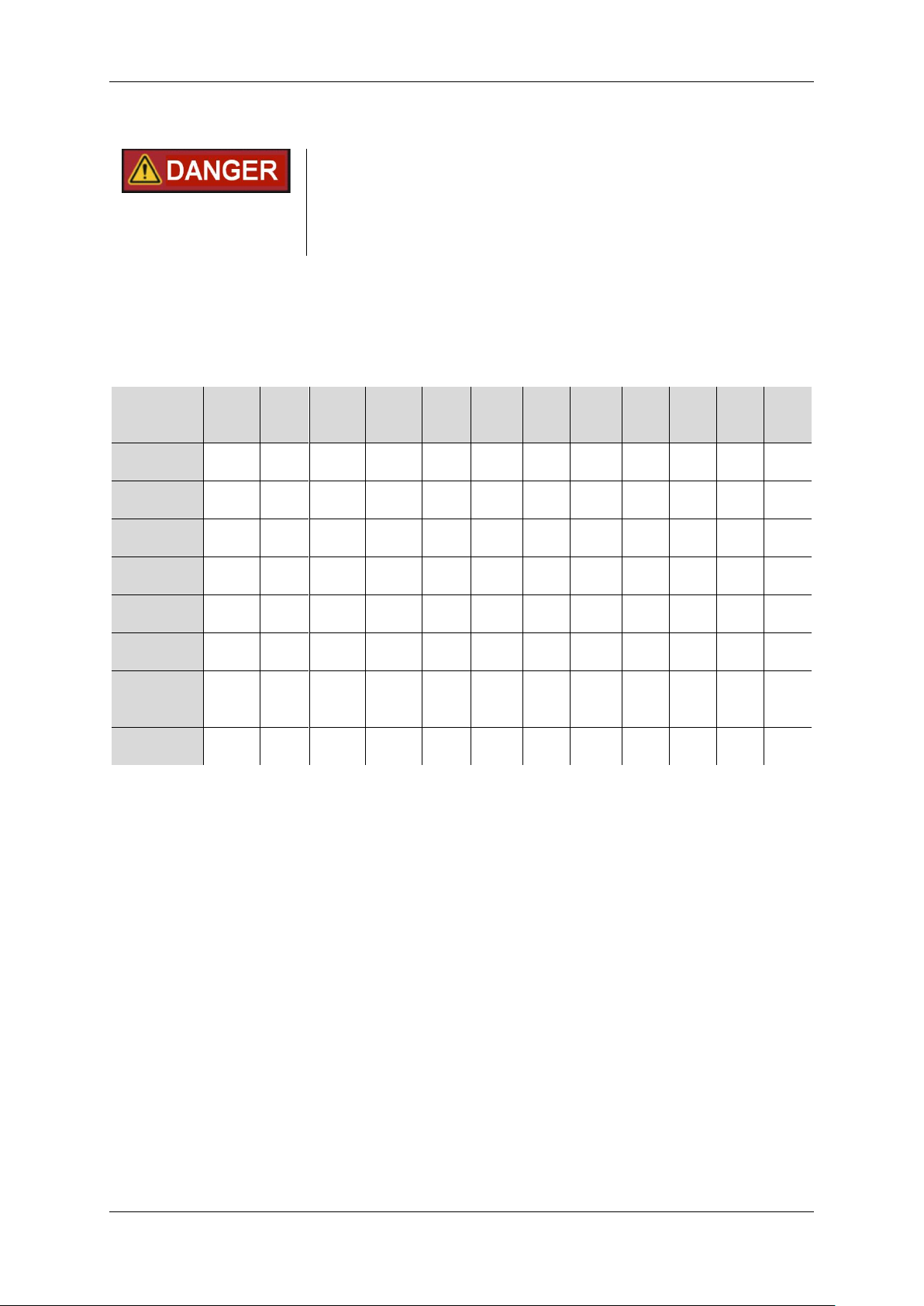
3.4 Technical Data
Airborne acoustical noise
This pump is not assigned to any direct workplace. The sound
pressure level of possible adjacent workplaces (LpA) is below 70 dB(A)
at full load. Measurement was performed according to EN ISO 3744 (at
a distance of 1m from the pump and 1.6m above the ground), the
measuring uncertainty is +/- 1.5 dB (Class 2.).
The rotating direction is specified by an arrow on the top cover. Viewed from above, the submersible
motor pump rotates counterclockwise.
The performance data are related to water. The pump medium must be chemically neutral and must
not exceed a maximum temperature of 65 °C. The admissible immersion depth is 40 m.
Model
AT
44F
AT
54F
AT
64O
AT
84O
AT
74O
AT
104O
AT
74S
AT
104S
AT
154S
AT
204S
AT
254S
AT
304S
Type of
installation
wet/
dry
wet
wet/
dry
wet/
dry
wet
wet
wet
wet
wet
wet
wet
wet
Pressure
joint DN
75
75
100
100
100
100
100
100
125
125
125
125
Pumping
head H
max
[m]
8 9 10
13
12
17
11
13
18
20
22
25
Flow rate
Q
max
[l/min]
2300
2500
2400
2800
3800
4200
4200
4800
5100
5700
6000
6700
Rated power
[kW/HP]
3.0
4.0
4.0
5.5
4.6
6.3
6.0
8.2
5.5
7.5
7.5
10.0
5.5
7.5
7.5
10.00
11.0
15.0
15.0
20.0
18.5
25.0
22.0
30.0
Rated speed
[rpm]
1440
1426
1450
1450
1450
1450
1450
1450
1460
1460
1474
1468
Rated current
[A] (at 400 V
and 50 Hz)
6.3
7.8
9.5
12.5
10.9
15.2
10.9
15.2
21.2
28.9
38.0
43.0
Weight
approx. [kg]
76
76
130
130
130
138
133
141
196
210
220
225
Standard versions:
• Stator, insulation class F (155°C) or H (180°C)*, class of protection: IP68
• Operating voltage 400 Volt, 50 Hz, 3-phase
• Switch with phase inverter or automatic control system *
• Thermal winding protection with built-in thermal contacts
• Thermal control system in the switch equipment
• Mechanical seal motor and medium-side
• Sealing sensor in oil chamber
• Electronic leakage control in the switch *
• Housing parts made from cast iron CI
• Tearing device* on the inlet nozzle made from fine tungsten carbides (>1900 HV) in a NiCr-
Matrix (60-65 HRC)
Impeller*:
• Non-clogging vortex impeller
• Open impeller (not for medium with clogging contents)
• Impeller/propeller blade made from cast iron CI
• Tearing device on propeller blade made from coarse-grained tungsten carbides (>2300 HV) in
steel matrix
(* according to model and version)

Franz Eisele u. Söhne GmbH & Co. KG
Page 14 of 41
3.5 Modification to the Product
Unauthorised modifications to the product may negatively affect the safety, service life or function of
the product. All changes that are not described in the product documentation are not permitted.
For reasons of safety, no unauthorised modifications may be undertaken! All planned modifications
must be authorised in writing by the manufacturer.
Arbitrary, unauthorised modifications to the product lead to the loss of warranty claims, invalidate the
enclosed manufacturer or installation declarations and increase the risk of damage.
3.6 Electrical Protection and Monitoring Equipment
Fault Current Switch (RCD):
A fault current switch (RCD) with a rated leakage current of maximum 30 mA is to be installed by the
user for every individual submersible motor pump, in addition to the prescribed fuse protection. In the
case of a fault, this RCD should activate all power circuits, incl. leakage control and thermal sensor.
Motor Protection:
When using motor protection switches with only bimetal trips, no reliable shutdown is guaranteed for
overheating, i.e. the thermal contacts integrated in the submersible motor are definitely to be looped
into the control circuit via an ATEX approved tripping unit.
Thermal Monitoring:
Thermal contacts are installed in the submersible motor for monitoring the temperature. That ensures,
that with defective motor cooling a reliable shutdown takes place. If no switch/ no control system of
Eisele is in use, in addition a motor protection switch/motor protection relay must be used. The motor
protection switch/ motor protection relay must be temperature-compensated and phase-failure
sensitive. The motor can only be switched on again after it has cooled down and the cause of the fault
has been eliminated.
Leakage Control:
A sensor is mounted in the oil chamber, which signals the ingress of fluid by means of a signal lamp of
the evaluation electronics (on the switch or in the control system).
If signalled: Carry out an oil change and check the motor compartment. If the signal lamp lights up
again, the mechanical seal must be replaced.
Attention: This leakage control is a very important component, in order to ensure the function of the
submersible motor pump. At the same time it is an item of operating equipment that helps to ensure the
observance of the protection objective. It is not permitted to put the device into operation without
leakage control. Its function is to be checked and assured during commissioning, as well as monitored
at regular short intervals. The evaluation electronics necessary for this is available as an accessory.
 Loading...