


Advantage 2000 System
Manual
eircom advantage 2000
System Manual

Advantage 2000 System Manual
Page 2
Specifications are subject to change without notice.
Facilities described may or may not be supported by your network.
Advantage 2000 and Advantage are the registered trademark of MDS Gateways.
This documentation refers to:
software version 20.044 or higher for the IP system phones and
software version 11.100 or higher for the Advantage 2000 system.
DM 1041 rev 2

Advantage 2000 System Manual
Page 3
Contents
11.
.
IInnttrroodduuccttiioonn
5
5
1.1. Overview of the Advantage 2000 ......................................................................... 5
1.2. Status LEDs ........................................................................................................... 6
1.3. Back Panel Connectors and Fax port .................................................................. 6
1.4. Features and Dialling Codes ................................................................................ 7
1.5. Login to your personal page ............................................................................... 8
1.6 Hotdesking ............................................................................................................ 9
22.
.
SSyysstteemm MMoouunnttiinngg,, WWiirriinngg aanndd CCoonnnneeccttiioonn oonn tthhee LLAANN
110
0
2.1. Sequence required for installation .................................................................... 10
2.2. Location ............................................................................................................... 10
2.3. Equipment ........................................................................................................... 10
2.4. Wall Mounting the Advantage 2000 ................................................................... 10
2.5. System Wiring ..................................................................................................... 11
2.6. Three step Set-up flow chart .............................................................................. 12
2.7. Program the IP address of the system into the range of the LAN ................... 14
33.
.
CCoonnffiigguurree tthhee ssyysstteemm ffrroomm tthhee BBrroowwsseerr
117
7
3.1. Browser based programming ............................................................................ 17
3.2. Enter Browser Based Programming .................................................................. 17
3.3. System Programming Page ............................................................................... 19
3.4. Manual Programming of the SIP trunk lines ..................................................... 20
3.5. Programming the External Lines ....................................................................... 24
3.6. Programming the Ringing Assignment ............................................................. 27
3.7. Programming the Trunk Access digit ................................................................ 29
3.8. Programming other features .............................................................................. 30
44.
.
GGeett IInntteerrnneett AAcccceessss
331
1
4.1. Universal Plug and Play available on site ......................................................... 31
4.2. If the modem router is not at the default Gateway IP address ......................... 32
4.3. If the modem router does not support Universal Plug and Play...................... 33
55.
.
CCoonnnneecctt IIPP ssyysstteemm pphhoonneess
334
4
5.1. Connecting IP system phones ........................................................................... 34
5.2. Auto discovery of IP system phones on the LAN ............................................. 35
5.3. Connecting an IP system phone remotely across the public Internet ............ 35
5.4. Entering the system phone IP registration parameters manually ................... 35
66.
.
AAddddiittiioonnaall ssooffttwwaarree lliicceenncceess
336
6

Advantage 2000 System Manual
Page 4
Appendix I Power over Ethernet and Ethernet cable specifications ......................... 37
Standard Ethernet Cable ................................................................................................ 37
Appendix II System Tones .......................................................................................... 37
Appendix III Compatibility with third party headsets and analogue phones .............. 38
Appendix IV Miscellaneous timer settings ................................................................... 39
Appendix V Environmental Specifications .................................................................... 40
Appendix VI User settings, trunk accesses, ringing assignments and CLIs ........ 41
Appendix VII Common Address Book Table ................................................................. 44
Appendix VIII IP Addresses and RAS Tables ................................................................ 45
Appendix IX Call Logging outputs and formats ............................................................ 46
Diagnostic Logging ......................................................................................................... 51
Appendix X Example: how to configure port forwarding on the Netopia modem router
Cayman 3346 ................................................................................................................... 53
Appendix XI Usage of the 12 communication channels available on the system ...... 67

Advantage 2000 System Manual
Page 5
11.. IInnttrroodduuccttiioonn
1.1. Overview of the Advantage 2000
The Advantage 2000 is a next generation IP voice switch for SOHO and small
business applications. The system connects four analogue telephones and up to 16
IP system phones to the public ISDN, PSTN or SIP networks.
Users make or receive calls via the PSTN/ISDN network or via a SIP server in the
public network, using a simple analogue phone or an Advantage IP Executive phone
or an Advantage IP Professional phone.
The Advantage IP Executive is an advanced multi function system phone with 16
programmable keys, 6 fixed keys, loudspeaker and a blue backlit 4-line display.
The Advantage IP Professional is an advanced multi function system phone with 6
fixed keys, loudspeaker and a blue backlit 4-line display.
Up to sixteen of these phones may be connected locally to the Advantage 2000
system or remotely over broadband Internet. Remote IP phones have full system
functionality. The system phones have a two-port Ethernet hub, which allows a single
cable to the desktop for both the phone and the PC.
The Advantage 2000 has a full range of pbx features including voicemail, automated
attendant, least cost routing, speed dials, address books and call lists. Features such
as networking of multiple systems on different sites require the installation of a
license. Licenses can also be installed to expand the number of users or the number
of voicemail boxes and for PC-based soft phones,.
Advantage 2000 System Manual
Page 6
1.2. Status LEDs
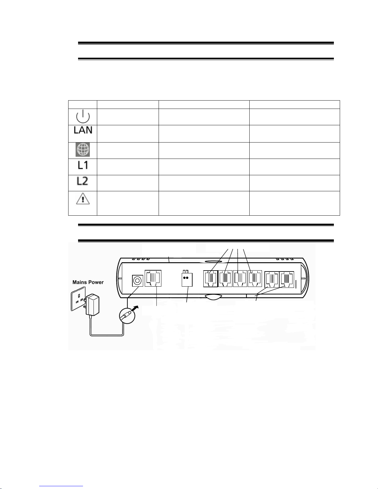
There are six LEDs behind the clear lens on the front of the unit. The functions of
these are as follow, from left to right.
LED
Status: ON
Status: OFF
Status: Flashing
System starting Power off Power On. Normal
operation.
LAN link present No LAN link present LAN activity
SIP server
connection OK
SIP server connection
NOT OK
One or more SIP accounts
NOT OK
ISDN BRA
connected at L1
N/A N/A
ISDN BRA
connected at L2
N/A N/A
Fault Condition.
Contact technical
support
No fault condition N/A
1.3. Back Panel Connectors and Fax port
Ethernet
Doorphone
Relay
4 analogue a/b ports
ISDN or PSTN Trunk Lines
31 3 2 3 3 3 4
Power Port: For connecting the power adaptor.
Ethernet Port: For connecting the unit to a router or LAN.
Doorphone Relay: For connecting a doorphone relay
Analogue Ports 31- 34: for connecting analogue a/b extensions
Fax Port: Fax machines should be connected to analogue port 34.
L1 and L2: For connecting the unit to ISDN or PSTN trunk lines from the public
network.

Advantage 2000 System Manual
Page 7
1.4. Features and Dialling Codes
Feature
Code
Any trunk line 9
SIP trunk line *00
Trunk lines 1 or 2 * 9 1 or * 9 2
SIP trunk lines 1 to 10 * 901 to * 910
Groups 80 to 89 80 to 89
Forward all calls to internal user * 2 1 * <user number> #
Forward all calls to voicemail * 2 1 * < * 9 9 > #
Forward all calls to external number * 2 1 0 * <external number> #
Cancel forwarding of all calls # 2 1 #
Restrict your outgoing CLI * 30 #
Send your outgoing CLI * 31 #
Common address book short codes * 4 0 0 0 to * 4 1 9 9
Personal address book short codes * 8 0 0 to * 8 4 9
Forward on No Answer to internal user * 6 1 * <user number> #
Forward on No Answer to internal user with timer * 6 1 * <user number> * <time> #
Forward on No Answer to voicemail * 6 1 * < * 9 9 > #
Forward on No Answer voicemail with timer * 6 1 * < * 9 9 > * <time> #
Forward on No Answer to external number * 6 1 0 * <external number> #
Forward on No Answer to external number with timer * 6 1 0 * <external number> * <time> #
Cancel Forward on No Answer # 6 1 #
Camp On (Call Back on busy) internal 5
Do Not Disturb * 6 2 #
Cancel Do Not Disturb # 6 2 #
Opt out of a group * 6 2 * <group number(80 – 89)> #
Opt into a group # 6 2 * <group number(80 – 89)> #
Forward on Busy to internal user * 6 7 * <user number> #
Forward on Busy to voicemail * 6 7 * < * 9 9 > #
Cancel Forward on Busy # 6 7 #
Activate Roaming PIN * 6 8 <Roaming Account> <Roaming PIN> #
CallPickUp/CallPickOff * 7 1 <user number>
Universal pickup * 7 1 0
Call Transfer Explicit (at dial tone with two calls on hold) * 7 2
Conference (at dial tone with two calls on hold) * 7 3
Park/Unpark a call * 7 4
Retrieve a parked call from an internal user * 7 5 <user number>
Answer a universal page * 7 6 *
Directed page * 7 7 <user number>
Universal page * 7 7 *
Door opening code * 7 8
Intrude (at busy tone) * 7 9
Access voicemail * 9 9
Transfer call to Mailbox (While ringing the User) # 99
Direct access to an user when answered by the Auto
Attendant
* + user number
Direct access to an user voicemail when answered by the
Auto Attendant
# + user number
Access voicemail settings (when pressed while listening to
voicemail welcome message)
#
Programming
Code
Program an external number in your personal address
book.
* * 8 0 0 to 8 1 9 *<external number> #
Erase a number from your personal address book. # 8 0 0 to 8 1 9 #
Implement Ringing mode (Modes 1 to 5) * 0 7 * <Ringing Mode > #
Enter System Programming * * * * # # # #

Advantage 2000 System Manual
Page 8
1.5. Login to your personal page
You can easily manage your Advantage settings, personal phonebook, call diversions
and voicemails by logging into the Advantage 2000 from a PC. Contact the
Advantage 2000 system administrator to receive your Username and PIN.
If your PC is connected on the same network as the Advantage 2000 system, type
the internal address of the Advantage 2000 into you browser:
http://192.168.1.250
This is the default IP address of the Advantage 2000. In order to connect, the PC
must have an IP address in the same range as the Advantage 2000 (ie)
192.168.1.XXX but different from the Advantage 2000. If it does not you must change
the IP address of the PC or the Advantage 2000 as described in the Advantage
2000user guide.
If you wish to connect to the Advantage 2000 from a remote location, type the WAN
IP address of the system followed by the port number. For example-
http://92.18.137.42:7000
In the login panel type your username and password and your personal IPhone page
will be displayed:

Advantage 2000 System Manual
Page 9
On this page you can search or edit your personal address book, set your call
diversions, programme an alarm call, change your PIN code, manage your voicemail
and your phone settings.
If you are connecting to the system from a remote location you can use the remote
office feature . This allows you to make and receive calls using your Forum 3000
phone number at a remote location. Type in the remote phone number where you are
currently located in the ‘Remote number’ box. This can be a GSM or a fixed number.
Type in the number you wish to call in the box ‘Dial’. The system will first call you
back at your remote number and then connect you to your required destination.
You can programme the keys on your phone as speed dials or function keys by
pressing the ‘Function keys’ button.
Phone language and volume settings can also be programmed on this page.
1.6 Hotdesking
A user of the Advantage 2000 may register from any Advantage IP connected to the
system. Once you have entered your IP registration name and PIN at a phone all your
calls will automatically ring at that phone. Check with the system administrator for
your IP phone registration name and registration PIN.
If you arrive at a hot desk and the phone is registered to another user, you can reregister it to your own user account as follows. Press the menus key and hold it down
for 5 seconds, scroll down to Registration Info and enter your IP registration name
and IP registration PIN. This can be done by repeatedly pressing the dial keys to
enter the characters. Press SET and then back and exit.
If the screen displays your extension number and a softkey called ‘Activate’ press the
softkey to activate the phone.

Advantage 2000 System Manual
Page 10
22.. SSyysstteemm MMoouunnttiinngg,, WWiirriinngg aanndd CCoonnnneeccttiioonn oonn
tthhee LLAANN
2.1. Sequence required for installation
It is important to follow the sequence in this manual of first verifying the compatibility
of the system IP address with the range of the LAN and then connecting the system
on the LAN, then accessing the system browser for configuration, then getting
Internet access and only then connecting the IP system phones to the LAN.
See also the 3-step set-up flow chart in this manual.
2.2. Location
The Advantage 2000 is designed for wall mounting. The air-cooling slots must not be
covered.
Find a location that is:
♦ Easily accessible and within 2 meters of the nearest available power point
♦ Isolated from plumbing or electrical wiring
♦ Not exposed to extremes of temperature, humidity, dust, chemicals or direct
sunlight
♦ Sufficiently spacious and well-lit to allow you to wire the system
2.3. Equipment
Equipment required for system installation:
♦ Two screws and rawl plugs suitable for the material to be drilled
♦ Drill and chuck-key
♦ Drill bit and flathead screwdriver
♦ CAT-5 cable to connect to the router or LAN.
♦ RJ 45 cables for the analogue users, relays and line connections
2.4. Wall Mounting the Advantage 2000
1. Place the Advantage 2000 unit against the wall and mark the positions of the
central fixing hole and the lower fixing hole.
2. Drill the holes, insert rawl plugs and insert screw into the wall at the location of
the central fixing hole, but leave it protrude about 5mm.
3. Place the unit onto the central fixing screw.
4. Fix the unit horizontally by inserting the second screw in the fixing hole at the
bottom of the unit.
The system is now ready for wiring.

Advantage 2000 System Manual
Page 11
2.5. System Wiring
Connecting the Ethernet Port.
Connect the Ethernet LAN port of the Advantage 2000 to the LAN connection point
using CAT-5 Ethernet cable. A 3m Ethernet cable is provided with the control unit.
The Ethernet port is compatible with any 10/100BaseT Ethernet switch.
Analogue Users 1 – 4
Plug the analogue telephones directly into the RJ45 analogue user ports at the back
of the Advantage 2000. The maximum analogue user line length is 1,000 metres.
Connecting the ISDN/PSTN lines
Connect the L1 and L2 line ports of the Advantage 2000 to the ISDN or PSTN
termination points using RJ45 line cables. Two ISDN line cables are provided with
the control unit.
Connecting the relay
Connect the relay port of the Advantage 2000 to the door phone using RJ45 cable, if
required.
Powering Up
Connect the AC mains power cable from the back of the unit to the AC power supply
using the plug-top adaptor power-supply provided.

Advantage 2000 System Manual
Page 12
2.6. Three step Set-up flow chart
Yes
Yes
Plug the system into the LAN, Point a PC browser
at the systems IP address. (default
http://192.168.1.250)
User name: admin
Password: 1000
Click on the link IP Addresses in the IP Settings
panel.
Enter your gateway IP address in the Default
Gateway field, and click save.
Change the Gateway IP address of the system
The system has
default Gateway IP
address
192.168.1.254.
Is this ok for you?
The system has a
default IP address
of 192.168.1.250
and mask of
255.255.255.0
IIss tthhiiss ookk ffoorr yyoouu??
The LEDs flash during the initiation sequence and finally just
the power LED flashes.
STEP 1. Power the Advantage system up
To hear the systems current IP address or Subnet
mask.
1. Plug an analogue phone into one of the
analogue ports
2. Dial **01# for the IP address or **02# for the
Subnet mask. 3. The system will call out the
current setting.
To change the systems current IP address or
Subnet mask.
1. Dial **01*DDD*DDD*DDD*DDD# for the IP
address or **02*DDD*DDD*DDD*DDD# for the
Subnet mask, where DDD represents the elements
of the IP address or subnet mask, i.e. dial
**01*192*168*0*100# to set the IP address to
192.168.0.100 or **02*255*255*255*254# to set
the subnet mask to 255.255.255.254
Change the IP address of the system
What you need to know
before you start:
1. The IP address range of the
LAN.
2. The IP address of the Router
on the LAN.
3. Does you Router Support
UPnP and is it enabled?

Advantage 2000 System Manual
Page 13
Manually Forward VoIP ports on the Router to the
internal IP address of the system
Is
Universal
Plug n Play
enabled on your
Router?
Browse to the Router’s Programming web page
and program port forwarding, so that the following
packets are forwarded to the IP address of the
system.
TCP packets arriving on port (5075)
UDP packets arriving on ports (50000-50031)
TCP packets arriving on port (7000) forwarded to
port (80).
Just take the IP system phone home and connect it to you home
LAN. The IP system phone will request an IP address from the
DHCP server in your router. (Note: If DHCP is not enabled in the
router, you will need to manually set the local IP address in the
Phone, see phone installation manual for this). Once it has a Local
IP address, it will then connect back to the system over the
Internet.
STEP 3. If you wish to use your IP system phone at a remote
location
The IP system phones request an IP address from the DHCP
server in the router. (Note: If DHCP is not enabled in the
router, you need to manually set the local IP address in each
Phone; see phone installation guide for this).
The phone then Auto-discovers the advantage system and
is assigned an IP registration name and an IP registration
PIN along with the WAN (public) IP address of the router.
That’s it. Your IP system phone should now be
connected to the Advantage system and be able to make
and receive calls
STEP 2. Connect the IP system phones to the LAN

Advantage 2000 System Manual
Page 14
2.7. Program the IP address of the system into
the range of the LAN
The default IP address of the Advantage 2000 is 192.168.1.250.
The IP address of the system must be in the range of the LAN to which it’s
connected. The system does not have either a DHCP client nor a DHCP server, to
minimise potential for conflicts.
If for example the LAN range is VVV.XXX.YYY.ZZZ, the first three elements of the IP
address of the system must be altered to VVV.XXX.YYY and the last element must
be taken from the range 1-255, but excluding those numbers at which devices are
already connected.
The IP address of the Advantage 2000 can be changed in a number of ways.
2.5.1. Change the IP address of the system using an analogue phone
Connect an analogue phone to one of the analogue ports of the Advantage 2000.
At internal dial tone, dial **01# and the Advantage 2000 system will announce its
internal IP address.
Enter new IP Address into the Advantage 2000:
Internal Dial
Tone
* * 0 1 * D D D * D D D * D D
D * D D D #
☺☺☺☺
System will set new IP Address
where each ‘DDD’ represents one element of the IP address.
Dial ‘**01*192*168*000*001#’ to assign the system the IP address 192.168.0.1.
☺☺☺☺
Smiley face indicates successful programming tone. You will get this
tone after you have successfully programmed an option. At this tone,
you should clear down.

Advantage 2000 System Manual
Page 15
Enter Subnet Mask:
Internal Dial
Tone
* * 0 2 * D D D * D D D * D
D D * D D
D
#
☺☺☺☺
System will set Subnet Mask
where each ‘DDD’ represents one element of the subnet mask.
Dial ‘**02*255*255*255*254#’ to assign the mask 255.255.255.254.
Check Local IP Address:
Internal Dial
Tone
*
* 0
1
#
System will read out Local IP
Address
Check Subnet Mask:
Internal Dial
Tone
*
* 0
2
#
System will read out Subnet Mask
2.5.2. Change the IP address of the system using a PC
Connect a PC directly to the LAN port of the system using an Ethernet cable.
Configure the IP address of the PC in the same address range as the
Advantage 2000 system, default address 192.168.1.250. The first three
elements of the IP address of the PC must be 192.168.1 and the last element
must be taken from the range 1-255, but excluding 250.
Open a browser on the PC and point it at the the Advantage 2000 system
default address 192.168.1.250.
Login to the system with the username ‘admin’and the password ‘1000’.
Click on the link ‘IP Adresses’ in the section ‘IP settings’, change the IP
address of the system and press ‘Save’ .

Advantage 2000 System Manual
Page 16
IP Connection Testing
To check that the IP configuration is correct and both the PC and the Advantage 2000
are on the same network -
At the PC, from Windows -
• Go to <Start>
• Select <Run>
A window prompting the user to open a program will appear -
• Type "command" (or “cmd” in some cases for Windows 2000) in the white
field. The MS-DOS window opens with the following prompt - C:\_
• Type "ipconfig" at the cursor.
The details of the IP configuration of the PC will appear on the window - e.g.
Windows IP Configuration -
IP Address ......................... 192.168.1.251
Subnet Mask .................…… 255.255.255.0
Default Gateway ................ 192.168.1.254
Make sure that the configuration that appears on your PC is correct.
In order to test the IP connection between the PC and the Advantage 2000, type
"ping", followed by the IP address of the Advantage 2000. To test for the example
shown above, type -
Ping 192.168.1.250
The PC will ping the system with 32 bytes of data and report the results. If the IP
connection is correct, the results should state -
Packets: Sent=4, Received=4, Lost=0 (0% Lost).
If the IP connection is incorrect, check again that the system and the PC are in the
same IP address range and that the cabling connections are correct.
Safety Notes
This unit should only to be opened by service personnel.
There are no serviceable parts inside the housing

Advantage 2000 System Manual
Page 17
33.. CCoonnffiigguurree tthhee ssyysstteemm ffrroomm tthhee BBrroowwsseerr
3.1. Browser based programming
This section describes how to connect to the Browser interface on the Advantage
2000 and enter the basic configuration information needed for the operation of the
system. Once you have successfully connected to the browser, the full range of
features offered by the system can be programmed. The browser interface also
allows a software upgrade either locally by uploading it from a PC or remotely by
requesting it from a remote management server.
There is a Help Button on each feature-programming page. On clicking the Help
button, the Help page appears on screen giving an explanation of the feature and
indicating how to program the feature.
Programming is carried out from a PC using any standard Internet Browser, e.g.
Netscape Navigator or Microsoft Internet Explorer, that is connected to the system
either directly on the Ethernet Port or through a Local Area Network (LAN).
3.2. Enter Browser Based Programming
To use Browser Based Programming, the system and the PC must be on the same
network with an IP connection established between them as described above.
Open the Internet Browser and type the IP address of the system.
The default address is - http://192.168.1.250
The IP address of the system can be checked as described in section 2 above.
Once the IP connection is established, the following login page will be displayed:

Advantage 2000 System Manual
Page 18
Enter:
Username: admin
Password: 1000
The main configuration page will now be displayed.

Advantage 2000 System Manual
Page 19
3.3. System Programming Page
Following login, the main configuration screen, similar to that shown below, will be
displayed. This shows a list of all of the programmable settings for the system
divided into related groups for ease of programming.
Clicking on any one of these links will open the configuration page for that parameter.

Advantage 2000 System Manual
Page 20
3.4.
Manual Programming of the SIP trunk lines
The VoIP trunk lines of the Advantage 2000 may be configured automatically by the
network operator. However, should you need to programme the trunks manually, you
can do so by clicking the link ‘SIP Accounts’ under the heading SIP Trunks. The
following page will be displayed:
This page is used to display the status and parameters of the SIP external lines,
which connect to the Voice over IP public network. Each telephone number
corresponds to an account on the public VoIP network. Each account has a user
name and password. These details are provided by the operator of the network.
The parameters of the SIP accounts are displayed here. Press the ‘edit’ button to
configure. The following parameters are displayed.
NAME: The Advantage 2000 may allocate a name to each SIP account.
USERNAME: This is the username defined by the network operator for this SIP
account.
PROVIDER: This is location of the SIP server as defined by the network operator.
Typically it is in the format sip.operator.com.

Advantage 2000 System Manual
Page 21
TRUNK ACCESS: This is the line access code for this trunk. The user on an outgoing
call may select this particular trunk by dialling the line access code prior to dialling the
external number.
STATUS: Indicates whether the SIP account is operational or not.
Click on the ‘Edit’ button on the first line of this table. The following page will be
displayed:
This page is used to configure the SIP external lines that connect to the Voice over IP
Operator network. Each SIP trunk requires an account on the Operator network. The
network operator provides the details of this account.
The parameters of the SIP trunk are altered or edited on this page. The following
parameters may be configured:
Basic Settings
NAME: The Advantage 2000 system can allocate a name to each SIP trunk line.
TRUNK ACCESS: This is the line access code for the trunk. The user, on an outgoing
call, may select a particular trunk by dialling the trunk access code prior to dialling the
external number.

Advantage 2000 System Manual
Page 22
ENABLED: The line may be enabled or disabled here.
STATUS: Indicates whether the SIP trunk is operational or not.
Provider Settings
SIP SERVER: The location of the SIP server in the Operator’s network. The Operator
provides this information. Typically it will be in the format sip.operator.com.
SIP SERVER PORT: This is the PORT number for the SIP protocol. By default it is
5060. If the operator uses a different port number it should be entered here.
REGISTRATION REQUIRED: Is registration required by the network operator or
not?
FORCED PROXY IP: The actual SIP server IP address must be entered here if it's
different from the IP address associated with the SIP server URL. The SIP operator
may insist that all SIP messages are relayed to the forced proxy IP address entered
here; the SIP server URL is included in the SIP messages from the system.
REGINTERVAL: The SIP protocol allows for periodic registration messages to be
sent to the SIP server in order to keep it updated it on the status of the SIP client. The
parameter RegInterval allows the system administrator to program the length of the
registration interval in seconds.
STUN SERVER: Some operators require the use of a STUN server (Simple Traversal
of UDP through NATS). If the operator provides the address of a STUN server with
the account details, it should be entered here.
Subscriber Settings
USERNAME: This is the username provided by the network operator for the SIP
account.
PASSWORD: This is the password provided by the network operator for the SIP
account.
AuthID: Authorisation ID, if required, is provided by the network operator.
EXTERNAL NUMBER: This is the public telephone number associated with this SIP
account. It is provided by the network operator and should be entered here. It is then
added automatically to the list of external telephone numbers of the system.
Audio Settings
Codec priority 1,2,3: These fields are used to set the preferred audio codecs.
DTMF Method: This parameter allows the system administrator to select the method
of transmitting DTMF digits across the VoIP network.

Advantage 2000 System Manual
Page 23
Dialling Settings
DIAL PLAN: During dialling on outgoing calls, the digits are stored until the complete
number has been dialled and then the complete number is transmitted en bloc to the
VoIP network. A period of three seconds without dialling is interpreted by the system
as the end of dialling. This means that the system must delay transmitting the number
for a period of 3 seconds after the end of the last digit. The Dial Plan allows the
system administrator to define number types that can be dialled immediately without
waiting for the 3-second period to elapse.
For example, the entry
[2-8]XXXXXX=,08[567]XXXXXXX=,999=,911=
will be interpreted by the system as follows:
Any number with first digit 2,3,4,5,6,7 or 8 followed by six digits may be dialled
immediately and
Any number beginning with 08 and whose third digit is 5,6 or 7 followed by seven
digits may be dialled immediately and
The number 999 may be dialled immediately and
The number 911 may be dialled immediately.
DIAL TIMEOUT: This is a pre-defined period without dialling which is interpreted as
the end of dialling. The default is 3 seconds and this may be changed here by
specifying an alternative value.
Click [SAVE] to accept new settings.
The double arrows << and >> at the bottom of the page may be used to jump forward
or back to the next SIP account.
Click [BACK] to return to the SIP Accounts menu.

Advantage 2000 System Manual
Page 24
3.5. Programming the External Lines
The Advantage 2000 may have up to two external line interfaces. These, if fitted,
may be used to connect either ISDN To lines or analogue trunk lines.
You may program these lines as ISDN or analogue on the page ‘System Line
Selection’
When ISDN T0 lines are connected, you must program the ISDN telephone numbers
associated with each T0 interface into the Advantage system. These numbers are
entered on the ‘External Number List’ as shown below.

Advantage 2000 System Manual
Page 25
When the external numbers have been entered in the white boxes, press ‘Save’ and
‘Back’.

Advantage 2000 System Manual
Page 26
These ISDN external numbers must be associated with one or both of the T0 line
interfaces that may be on the system. This is required for outgoing ISDN calls to
present a CLI that is recognised as a valid number for the Trunk interface by the
ISDN network. This is done on the ‘External No. Trunk assignment’ page under ‘ISDN
Trunks’ as shown below.
For each external number, tick the ISDN T interface associated with this number and
press ‘Save’.

Advantage 2000 System Manual
Page 27
3.6. Programming the Ringing Assignment
Each external telephone number connected to the Advantage 2000 may be
programmed to ring a different user or set of users on incoming calls. The SIP trunk
assignment is done on the ‘Ringing assignment’ page in the section ‘External
Numbers’. The ISDN ringing assignment is done on the ‘Ringing Assignment’ page
under ‘External Numbers’. The analogue line assignment is done on the ‘ Analogue
Ringing Assignment’ page under PSTN Analogue Trunks. The ringing assignment
may be changed for different times of the day. By default, three ringing modes are
defined, ’Day ringing’ and ‘Night ringing’ and Operator Mode and there are two
additional modes that can be defined by the user.
By default, all external lines are programmed to ring the first IP user, 11, of the
Advantage 2000. This user, in the default configuration, is defined as sole member of
the operator group, group 9.
This ringing assignment can be changed by typing the users or groups or AutoAttendant message to be called when an incoming call arrives on a particular line, as
shown below and pressing the SAVE button.
You may proceed to program another ringing mode by clicking on the link below the
table on the left.
Ringing Assignment Table for SIP Trunks

Advantage 2000 System Manual
Page 28
Ringing Assignment Table for Analogue PSTN trunk lines

Advantage 2000 System Manual
Page 29
3.7. Programming the Trunk Access digit
The trunk line access digit is the digit dialled by a user to make a call on an external
trunk. In addition to the default trunk line access code there are eight other codes
that may be allocated to the various external lines using the table below.
Trunk Access Codes
In the example shown below, IP1 to IP4 are SIP trunks and A5 is an analogue PSTN
trunk line.
Dialling the digit 0 will select any trunk line.
Dialling *91 will select the SIP trunk line IP1.
Dialling *92 will select the SIP trunk line IP2.
Dialling *93 will select the SIP trunk line IP3.
Dialling *94 will select the SIP trunk line IP4.
Dialling *95 will select the analogue PSTN trunk line A5.

Advantage 2000 System Manual
Page 30
3.8. Programming other features
Program all other features of the Advantage 2000 by clicking on the feature on the
System Programming page and following the instructions in the comprehensive online
Help available on every page.

Advantage 2000 System Manual
Page 31
44.. GGeett IInntteerrnneett AAcccceessss
4.1. Universal Plug and Play available on site
When the Advantage system is powered up it broadcasts a Universal Plug and Play
(UPnP) request to the Default Gateway address programmed in its IP Addresses table.
If the Advantage system gets a positive response at the programmed Default
Gateway address (default 192.168.1.254), it sets port forwarding at the Gateway,
based on the settings in the Gateway Configuration page (see below). It also queries
the Gateway for its WAN IP address (public IP address).
By default the Advantage system implements port forwarding of UDP packets on
ports 50000 to 50031 from the Gateway to the local IP address of the Advantage
system. Similarly, it implements port forwarding from the Gateway for TCP packets
on port 5075. It also forwards port 7000 to port 80 on the Advantage system to allow
remote browser access.

Advantage 2000 System Manual
Page 32
Note: For security, remote access to the Advantage system browser is restricted to
only those public IP address listed in the RAS IP addresses table.
4.2. If the modem router is not at the default
Gateway IP address
If the default local IP address of the modem router has been altered from
192.168.1.254, the Advantage system must be manually programmed with the IP
address of the Default Gateway (i.e. the router) for Internet access. The local Default
Gateway IP address is entered on the IP Settings browser page. This allows the
Advantage system to direct outgoing traffic to the correct Internet gateway. The
Gateway Configuration page is updated automatically to display the Local IP Address
entered (192.0.0.229 in the screen example shown above).

Advantage 2000 System Manual
Page 33
4.3.
If the modem router does not support
Universal Plug and Play
If the SIP ports of the modem router are not open by default and it does not support
UPnP, the appropriate WAN ports on the modem router Gateway must be forwarded
manually by accessing the modem router Gateway browser programming as per the
example in the Appendices.
UDP packets, typically on WAN ports 50000 to 50031 of the Gateway, should be
forwarded to the local IP address of the Advantage system and also TCP packets on
port 5075 and packets on browser port 7000 on the Gateway should be forwarded to
the Advantage system port 80.
It may well be necessary to lower the level of Firewall protection, as described in Step
2 of the example in the Appendices.

Advantage 2000 System Manual
Page 34
55.. CCoonnnneecctt IIPP ssyysstteemm pphhoonneess
5.1. Connecting IP system phones
Connect the IP system phone LAN ports to the network as shown. The PC port on the
IP telephone may be used to connect a PC , thus allowing a single cable from the
desk to carry the PC trafic and the telephone traffic.
Note: Do not connect any IP system phone to the LAN until the system has
access to Internet; otherwise the WAN address of the system (relayed by router
UPnP) will not be captured by the IP system phone at powerup.
Note: Do not power up the IP system phones until the system’s IP address is in
the correct range for the LAN, as decribed previously; otherwise the IP system
phones may be assigned IP addresses that are not within the same range as the
system and auto discovery cannot work properly.
Connect the LAN port of the Advantage IP system phone (Executive or Professional)
to the LAN using the Ethernet cable supplied with the phone.

Advantage 2000 System Manual
Page 35
5.2. Auto discovery of IP system phones on the
LAN
When the IP system phone is plugged into a LAN and powered up by Power-overEthernet (PoE standard 802.3af) or from the mains via its plug-top adaptor, it autodiscovers the Advantage 2000 system on the LAN and is automatically allocated an
IP registration name and an IP registration PIN. The system phone also stores the
internal and the public IP addresses of the Advantage system.
The phone is now ready for use.
Note: The Advantage 2000 system must be equipped with the appropriate software
licenses if more than eight IP system phones are connected.
5.3. Connecting an IP system phone remotely
across the public Internet
Once an IP system phone has learned its IP registration details by auto-discovery on
a LAN, it may be connected to its Advantage 2000 system, securely, remotely over
the public Internet by simply plugging it into a broadband router. It automatically
registers with its remote Advantage system, from anywhere in the world, over the
public Internet.
If the phone had not been connected with its system on a LAN, the public IP address
or url of the system must be entered at installation in the remote location; also the
system phone’s IP registration name and IP registration PIN (as they appear on the
IP Phone Registration page in browser based system programming).
5.4. Entering the system phone IP registration
parameters manually
If the system phone had not been connected with its Advantage 2000 system on a
LAN before delivery to the end user location, the phone will prompt the user to enter
the following parameters at power up at the remote location:
1. Public IP address of the server (remote Advantage system).
2. User IP registration name
3. User IP registration PIN
These parameters may be altered at any time by depressing the Menus key on the IP
system phone display for 10 seconds and scrolling and selecting the options required.
For connection to the system, these three parameters entered on the IP system
phone must correspond to those stored on the system, on the IP Phone Registration
page.

Advantage 2000 System Manual
Page 36
66.. AAddddiittiioonnaall ssooffttwwaarree lliicceenncceess
The System may be expanded and enhanced by the installation of licences for extra
capacity or new features such as:
.
Two SIP Trunks (max 10 in total)
Eight additional IP system phone licences, on the LAN or WAN (max 16 IP users in
total)
Additional four voice mail boxes, with email forwarding (max 30 in total)
wav./MP3 format Music on Hold with capacity for 20 minutes of downloadable music
Symbian SIP phone WLAN registration, per user (max 16 SIP registrations)
Soft phone registration (max 16)
Networking per system over two IP channels
One additional IP networking channel
Computer Telephony integration (screen
pops with dial from Outlook)
Check with your system supplier to purchase these licences.

Advantage 2000 System Manual
Page 37
A
A
A
p
p
p
p
p
p
e
e
e
n
n
n
d
d
d
i
i
i
x
x
x
I
I
I
P
P
P
o
o
o
w
w
w
e
e
e
r
r
r
o
o
o
v
v
v
e
e
e
r
r
r
E
E
E
t
t
t
h
h
h
e
e
e
r
r
r
n
n
n
e
e
e
t
t
t
a
a
a
n
n
n
d
d
d
E
E
E
t
t
t
h
h
h
e
e
e
r
r
r
n
n
n
e
e
e
t
t
t
c
c
c
a
a
a
b
b
b
l
l
l
e
e
e
s
s
s
p
p
p
e
e
e
c
c
c
i
i
i
f
f
f
i
i
i
c
c
c
a
a
a
t
t
t
i
i
i
o
o
o
n
n
n
s
s
s
Power over Ethernet
802.3 af, class 1 device.
5 Watts required per phone.
S
S
S
t
t
t
a
a
a
n
n
n
d
d
d
a
a
a
r
r
r
d
d
d
E
E
E
t
t
t
h
h
h
e
e
e
r
r
r
n
n
n
e
e
e
t
t
t
C
C
C
a
a
a
b
b
b
l
l
l
e
e
e
Ethernet cable is used to connect a hub to the system.
Pin 1 Orange/White
Pin 2 Orange
Pin 3 Green /White
Pin 4 Blue
Pin 5 Blue/White
Pin 6 Green
Pin 7 Brown/White
Pin 8 Brown
A
A
A
p
p
p
p
p
p
e
e
e
n
n
n
d
d
d
i
i
i
x
x
x
I
I
I
I
I
I
S
S
S
y
y
y
s
s
s
t
t
t
e
e
e
m
m
m
T
T
T
o
o
o
n
n
n
e
e
e
s
s
s
The following is a list of tones that are used on the system -
Internal Dial Tone Continuous
Busy Tone 500mS On - 500msS Off - 500mS On - 500mS Off.................
Ringing Tone 1 Sec On - 4 Sec Off - 1 Sec On - 4 Sec Off...................
Hold Tone 30mS On - 100mS Off - 30mS On - 2 Sec Off - 30mS On - 100mS Off........
Congestion Tone & 250mS On - 250mS Off -250mS On - 250mS Off..................
Call Proceeding Tone
Success Cadence 500mS On - 55mS Off - 500mS On - 55mS Off.................
Failure Cadence 87mS On - 87mS Off - 87mS On - 87mS Off..................
Alert Tone 5 Sec Off: 120mS On - 9 Sec Off - 120mS On - 9 Sec Off...................
DND/Diversion Tone 500mS On - 55mS Off - 500mS On - 55mS Off.....................
Note: Sec = Seconds
mS = milli-Seconds
Pin 1 Orange/White
Pin 2 Orange
Pin 3 Green/White
Pin 4 Blue
Pin 5 Blue/White
Pin 6 Green
Pin 7 Brown/White
Pin 8 Brown

Advantage 2000 System Manual
Page 38
A
A
A
p
p
p
p
p
p
e
e
e
n
n
n
d
d
d
i
i
i
x
x
x
I
I
I
I
I
I
I
I
I
C
C
C
o
o
o
m
m
m
p
p
p
a
a
a
t
t
t
i
i
i
b
b
b
i
i
i
l
l
l
i
i
i
t
t
t
y
y
y
w
w
w
i
i
i
t
t
t
h
h
h
t
t
t
h
h
h
i
i
i
r
r
r
d
d
d
p
p
p
a
a
a
r
r
r
t
t
t
y
y
y
h
h
h
e
e
e
a
a
a
d
d
d
s
s
s
e
e
e
t
t
t
s
s
s
a
a
a
n
n
n
d
d
d
a
a
a
n
n
n
a
a
a
l
l
l
o
o
o
g
g
g
u
u
u
e
e
e
p
p
p
h
h
h
o
o
o
n
n
n
e
e
e
s
s
s
Headsets
The full range of Plantronics ‘H’ Top Headsets works on the Advantage Executive
system phone. The headset plugs directly into the headset port using a Vista to QD
(Quick Disconnect) Cable.
Product
Range
Part
Code
Description
Advantage
Cable
26716-01 Vista Headset to QD (Quick Disconnect)
Supra 32184-04 H51 Headset (One Ear + Headband)
32186-04 H51N Noise Cancelling Headset (One Ear + Headband)
Tristar 33647-01 H81 Tristar Headset (Over One Ear)
33693-01 H81N Noise Cancelling Tristar Headset (One Over Ear)
Encore 33645-41 H91 Headset (One Ear + Headband + Treble / Bass Control)
33699-41 H91N Noise Cancelling Headset (1 Ear + Headband + Treble/Bass Control
33646-11 H101 Headset (Two Ear + Headband + Treble / Bass Control)
33705-11
H101N Noise Cancelling Headset (Two Ear + Headband + Treble / Bass
Control)
DuoPro 36363-01 DuoPro H171 Combo Headset (One Ear+Headband & Over Ear)
36366-01
DuoPro H171N Noise Cancelling Combo Headset (One Ear+Headband &
Over Ear)
36568-01 DuoPro H181 Headset (Behind the Head)

Advantage 2000 System Manual
Page 39
Analogue phones
Compatibility of some analogue phones with MDS Advantage systems:
ULYTEL II
PHONE
WITH
MESSAGE
WAITING
SIEMENS
EUROSET
2010
SIEMENS
EUROSET
2015
SIEMENS
GIGASET
4010
CLASSIC
SIEMENS
EIRCOM
4012
SIEMENS
EIRCOM
5012
COLOUR
SIEMENS
GIGASET
C 150
SIEMENS
EIRCOM
4012
MICRO
Last Number
Redial
Yes Yes Yes Yes Yes
Time Break
Recall (transfer,
etc)
Yes Yes Yes Yes Yes
Rings with a
different Internal
and External
Ring Cadence
Yes No * Yes No* Yes
Message
Waiting audible
indication
Yes Yes Yes Yes Yes
Message
Waiting visual
indication
No Not
applicable
Not
applicable
Not
applicable
Yes
Caller Display
(CLI)
No No No Yes Yes
Programmable
keys can be
Programmed as
MDS PABX
function keys
Yes** Yes Yes N/A N/A N/A N/A N/A
* Does not differentiate between Internal and External ring cadence. Rings with one
cadence only.
**It is necessary to insert a Pause after Recall when programming function keys.
A
A
A
p
p
p
p
p
p
e
e
e
n
n
n
d
d
d
i
i
i
x
x
x
I
I
I
V
V
V
M
M
M
i
i
i
s
s
s
c
c
c
e
e
e
l
l
l
l
l
l
a
a
a
n
n
n
e
e
e
o
o
o
u
u
u
s
s
s
t
t
t
i
i
i
m
m
m
e
e
e
r
r
r
s
s
s
e
e
e
t
t
t
t
t
t
i
i
i
n
n
n
g
g
g
s
s
s
No TIMER Default
New
Setting
Maximum
Minim
um
1 Transfer Timeout 30 secs 3 mins 5 secs
2 Parked Call Timeout 3 mins 15 mins 10 secs
3 Forward No Answer Timeout 20 secs 3 mins 5 secs
4 Normal Disconnect Timer 20 secs 1 min 0 secs
5 Handsfree Disconnect Timer 3 secs 1 min 0 secs
6 Pause Timer 2 secs 1 min 0 secs
7
Maximum Voice Message
Length
90 secs 180 secs 0 secs
8 Browser Timeout 15 mins 15 mins 30 secs
9 Phone Menu Timeout 60 secs 3 mins 15 secs
10 Call Back Timer 1 10 secs 15 mins 0 secs
11 Call Back Timer 2 20 secs 15 mins 0 secs
12 Call Back Timer 3 60 mins 4 hours 1 min
13 Roaming PIN Timer 30 secs 15 mins 0 secs
14 Hotline Timer 10 secs 60 secs 0 secs
15 Internet Disconnect Timer 3 mins 999 secs 1 secs
16 Trunk To Trunk Timer 2 mins 999 secs 10 secs
17 Trunk Line Supervision 90 msecs 999 msecs 60 msecs

Advantage 2000 System Manual
Page 40
A
A
A
p
p
p
p
p
p
e
e
e
n
n
n
d
d
d
i
i
i
x
x
x
V
V
V
E
E
E
n
n
n
v
v
v
i
i
i
r
r
r
o
o
o
n
n
n
m
m
m
e
e
e
n
n
n
t
t
t
a
a
a
l
l
l
S
S
S
p
p
p
e
e
e
c
c
c
i
i
i
f
f
f
i
i
i
c
c
c
a
a
a
t
t
t
i
i
i
o
o
o
n
n
n
s
s
s
Operating temperature -5C to + 45C
Humidity 10% to 90% non-
condensing
Mains voltage
230 ± 10%
Max power consumption 66 W
Maximum AC V/A: 120VA
Maximum input watts: 66W
Maximum input current at
230Vac:
0.52A
Maximum input current at
180Vac:
0.67A
Power Factor: 0.55
Extreme working
conditions
-15C to + 55C
Storage temperature -20C to + 70C
Storage humidity 10% to 90% non-
condensing

Advantage 2000 System Manual
Page 41
A
A
A
p
p
p
p
p
p
e
e
e
n
n
n
d
d
d
i
i
i
x
x
x
V
V
V
I
I
I
U
U
U
s
s
s
e
e
e
r
r
r
s
s
s
e
e
e
t
t
t
t
t
t
i
i
i
n
n
n
g
g
g
s
s
s
,
,
,
t
t
t
r
r
r
u
u
u
n
n
n
k
k
k
a
a
a
c
c
c
c
c
c
e
e
e
s
s
s
s
s
s
e
e
e
s
s
s
,
,
,
r
r
r
i
i
i
n
n
n
g
g
g
i
i
i
n
n
n
g
g
g
a
a
a
s
s
s
s
s
s
i
i
i
g
g
g
n
n
n
m
m
m
e
e
e
n
n
n
t
t
t
s
s
s
a
a
a
n
n
n
d
d
d
C
C
C
L
L
L
I
I
I
s
s
s
USER SETTINGS TABLE 1 (Users)
User New User
Number
New
User
Name
Trunk Line Access
T/L1 T/L2 T/L3 T/L4
T/L5 T/L6 T/L7 T/L8
Level of Access
1 2 3 4 5 6 7
Users with Operator
Functionality Enabled
11
12
13
14
15
16
17
18
19
20
21
22
23
24
25
26
31
32
33
34
The default settings are - all users have access to all trunk lines
- all users have unrestricted access Level 7
USER SETTINGS TABLE 2 (Users)
User
External Call
Waiting
Internal Call
Waiting
Intrude
Intrude Protection
Call Pick-Off
Call Pick-Up
Do Not Disturb
(DND)
DND Override
Call Diversion
Conference
Internal Paging
Direct Line Seizure
(DLS)
User Programming
Voice Mail
Voice Mail Password
Call Back
Called Party
Missed Call List
Roaming PIN
Extensions
11
12
13
14
15
16
17
18
19
20
21
22
23
24
25
26
31
32
33
34

Advantage 2000 System Manual
Page 42
RINGING ASSIGNMENT TABLE
Index
MSN/ LINE
NUMBER
RINGING ASSIGNMENT
(Enter the extensions to ring for the MSN/Line for each ringing mode)
DAY RINGING
NIGHT RINGING
MODE 3
MODE 4
MODE 5
1
2
3
4
5
6
7
8
9
10
11
12
13
14
15
16
17
18
19
20
21
22
23
24
25
26
27
28
29
30
31
32
33
34
35
36
37
38
39
40
41
42
43
44
45
46
47
48
49

Advantage 2000 System Manual
Page 43
Index
MSN/ LINE
NUMBER
RINGING ASSIGNMENT
(Enter the extensions to ring for the MSN/Line for each ringing mode)
DAY RINGING
NIGHT RINGING
MODE 3
MODE 4
MODE 5
50
51
52
53
54
55
56
57
58
59
60
61
62
63
64
65
66
67
68
69
70
71
72
73
74
75
76
77
78
79
80
81
82
83
84
85
86
87
88
89
90
91
92
93
94
95
96
97
98
99
100
USER CLI TABLE
USER CLI NUMBER CLI
RESTRICTION
SET
USER CLI NUMBER CLI
RESTRICTION
SET
11 25
12 26
13 31
14 32
15 33
16 34
17
18
19
20
21
22
23
24

Advantage 2000 System Manual
Page 44
A
A
A
p
p
p
p
p
p
e
e
e
n
n
n
d
d
d
i
i
i
x
x
x
V
V
V
I
I
I
I
I
I
C
C
C
o
o
o
m
m
m
m
m
m
o
o
o
n
n
n
A
A
A
d
d
d
d
d
d
r
r
r
e
e
e
s
s
s
s
s
s
B
B
B
o
o
o
o
o
o
k
k
k
T
T
T
a
a
a
b
b
b
l
l
l
e
e
e
NUMBER NAME
Barred
Prefix
NUMBER NAME
Barred
Prefix
NUMBER NAME
Barred
Prefix
1 2 3
4 5 6
7 8 9
10 11 12
13 14 15
16 17 18
19 20 21
22 23 24
25 26 27
28 29 30
31 32 33
34 35 36
37 38 39
40 41 42
43 44 45
46 47 48
49 50 51
52 53 54
55 56 57
58 59 60
61 62 63
64 65 66
67 68 69
70 71 72
73 74 75
76 77 78
79 80 81
82 83 84
85 86 87
88 89 90
91 92 93
94 95 96
97 98 99
100 101 102
103 104 105
106 107 108
109 110 111
112 113 114
115 116 117
118 119 120
121 122 123
124 125 126
127 128 129
130 131 132
133 134 135
136 137 138
139 140 141
142 143 144
145 146 147
148 149 150
151 152 153
154 155 156
157 158 159
160 161 162
163 164 165
166 167 168
169 170 171
172 173 174
175 176 177
178 179 180
181 182 183
184 185 186
187 188 189
190 191 192
193 194 195
196 197 198
199 200

Advantage 2000 System Manual
DM 1030 Page 45
A
A
A
p
p
p
p
p
p
e
e
e
n
n
n
d
d
d
i
i
i
x
x
x
V
V
V
I
I
I
I
I
I
I
I
I
I
I
I
P
P
P
A
A
A
d
d
d
d
d
d
r
r
r
e
e
e
s
s
s
s
s
s
e
e
e
s
s
s
a
a
a
n
n
n
d
d
d
R
R
R
A
A
A
S
S
S
T
T
T
a
a
a
b
b
b
l
l
l
e
e
e
s
s
s
System
Details
DEFAULT
SETTING
NEW
SETTING
IP Address
192.168.1.250
Subnet Mask
255.255.255.0
HTTP Port
80
Gateway IP
Address
192.168.1.254
DNS Address 192.168.1.254

Advantage 2000 System Manual
DM 1030 Page 46
A
A
A
p
p
p
p
p
p
e
e
e
n
n
n
d
d
d
i
i
i
x
x
x
I
I
I
X
X
X
C
C
C
a
a
a
l
l
l
l
l
l
L
L
L
o
o
o
g
g
g
g
g
g
i
i
i
n
n
n
g
g
g
o
o
o
u
u
u
t
t
t
p
p
p
u
u
u
t
t
t
s
s
s
a
a
a
n
n
n
d
d
d
f
f
f
o
o
o
r
r
r
m
m
m
a
a
a
t
t
t
s
s
s
The system outputs Call Logging Records for all external calls, both incoming and
outgoing, over the Ethernet port. The Call Logging Report can be generated using
HyperTerminal over the Ethernet Connection using a TCP/IP port.
In order to make it easier to read the output, each field is right justified (i.e. padded
with spaces) and separated from the next field by a comma. This output may be
extracted and used by external applications (for example, Microsoft Excel) to
generate reports and accumulate statistics. (It is beyond the scope of this guide to
describe how to use this output with external applications).
Connect a PC (Windows operating system) to the system LAN Port:
The HyperTerminal window appears. When an incoming/outgoing call is detected on
the system, a Call Logging Record will be generated at the end of the call.
•
Open the <Start> menu
• Click On <Programs>
• Click On <Accessories>
• Click On <Communications>
• Click on <HyperTerminal>
The window alongside will be shown
•
In the Connect Using field, select the
TCP/IP (Winsock) setting
• Enter the IP address of the system in the
Host Address field (by default,
192.168.0.100)
• Enter the Port number. This is always 5070

Advantage 2000 System Manual
DM 1030 Page 47
Example of the call logging output to hyperterminal
Call Logging format table
The format of the call logging data that is sent to the PC consists of 17 distinct fields
of variable length that provide a comprehensive list of attributes for each call as listed
below.
Field
ID
Description
Size
(Bytes)
Details
01.
Call ID 5 Numeric index to reference the call record.
02.
Date 8 Date of call in the format DD/MM/YY.
03.
Time 8 Time of call in the format HH:MM:SS.
04.
Line Number 20 Alphanumeric representation of Line number
(e.g. Line 01)
05.
Extension
number
20 Numeric representation of extension number
(e.g. 623)
6.
Extension
Name
20 Alphanumeric representation of extension name
(e.g. Joe Bloggs)
07.
Call Type 1 I= Incoming (Voice)
O= Outgoing (Voice)
T= Transferred
N= Internet (Data)
R= Remote Access
C= Time Retrieval
D= Software Download
08.
Connection 1 Y = Yes N = No
09.
Voice Card 1 V = Voice Mail A = Auto-Attendant
10.
Call Duration
8 Duration of call in the format HH:MM:SS
(connected time)
11.
Ring Time 5 Duration of ringing in the format MM:SS
12.
Calling 20 Alphanumeric

Advantage 2000 System Manual
DM 1030 Page 48
Number (CLI or “Unknown” if CLI not provided)
13.
Calling Name 20 Alphanumeric
(if there is a match found in the Common
Address Book)
14.
Called Number
20 Alphanumeric (Called Number/MSN of Called
Party)
15.
Called Name 20 Alphanumeric
16.
Roaming PIN 2 Numeric representation of a roaming PIN User
No.
(e.g 02) for Roaming PIN user 02
17.
Call Cost 8 Numeric representation of the cost of the call in
Euros
Logging Incoming Calls
When an incoming call is answered by an extension, the “Call Type” (field 7) and
“Connection” (field 8) fields are updated to “I” and “Y” respectively in the
HyperTerminal window at the end of the call:
Example of a call record for an incoming call that is answered
1, 12/08/04, 17:30:02, Line 03, 654, John Lawler, I, Y, , 00:00:44, 00:05, 0872979676, , 8160058, ……
1 2 3 4 5 6 7 8 9 10 11 12 13 14 ……..
Logging Outgoing Calls
When an outgoing call is made by an extension, the “Call Type” (field 7) and
“Connection” (field 8) fields are updated to “O” and “Y” respectively in the
HyperTerminal window at the end of the call:
2 , 12/08/04, 17:12:01, Line 01, 676, Joe Bloggs, O, Y, , 00:00:03, 00:24, 8160016, , 05280669, …….
1 2 3 4 5 6 7 8 9 10 11 12 13 14 …….
Logging Voice Mail Calls
An incoming call that is directed to a user’s Voice Mail will generate a call record as
described for incoming calls. The “Voice Mail” field, 9, is updated to ‘V’ when the line
is connected to a voice mail channel. The “Connection” field (field 8) will be “Y” or “N”
depending on whether the calling party left a message on the extension’s mailbox.
Connection = ‘Y’ (“message left”)
Example of a call record for an incoming call that was answered by the voicemail and
then left a message:
3 , 12/08/04, 17:16:02, Line 02, 8160058 , , I, Y, V, 00:00:39, 00:00, 8160058, …………….

Advantage 2000 System Manual
DM 1030 Page 49
1 2 3 4 5 6 7 8 9 10 11 12 ………………………
Logging Transfer Calls
Two call logging records are generated when an incoming call is answered by
an extension and then transferred to another extension on the system. The
“Call Type” (field 7) is updated to ‘T’ on the transferred call to indicate that it is
a ‘Transfer’ type of call. The “Call ID” (field 1) remains the same for both
records.
Example of a call record for an incoming call that was answered by Joe Bloggs and
transferred to Jane Doe.
4 , 12/08/04, 17:16:02, Line 02, 627 , Joe Bloggs, I, Y, , 00:00:20, 00:03, 8160058, …………………….
4 , 12/08/04, 17:16:22, Line 02, 628 , Jane Doe , T, Y, , 00:00:39, 00:05, 8160058, …………………….
1 2 3 4 5 6 7 8 9 10 11 12
Logging Externally Forwarded Calls
If a user has externally forwarded his/her extension, there will be 2 separate Call
records (i.e. there are 2 separate Call IDs) for an incoming call that is externally
forwarded. In both of these records the Extension Number, Extension Name & the
Calling Number of the forwarding extension are stored.
Logging Auto-attendant Calls
If an incoming call is answered by the Auto-attendant then field 9 is updated to “A”. If
the call is then answered by an extension, there is a separate Call Logging record
(with the same Call ID) created for the answering extension as if the call had been
transferred to the user
Example of a call record for an incoming call that is answered by the Auto-attendant
and subsequently answered by an extension.
5 , 12/08/04, 18:26:02, Line 04, 600 , Reception , I, Y, A , 00:00:10, 00:05, 0871738729, …………….
5 , 12/08/04, 18:26:12, Line 04, 627 , Joe Bloggs , I, Y , , 00:00:25, 00:03, 0871738729, ……………..
1 2 3 4 5 6 7 8 9 10 11 12 ………………………
Logging Time From Network Calls
The Advantage system can be programmed to automatically make a call on power-up
in order to extract the time provided by the ISDN network. This call will immediately

Advantage 2000 System Manual
DM 1030 Page 50
be cleared down as soon as the connection is established and the time information
has been extracted from the connect message. When a “retrieve time from network”
call is made the “Call Type” ( field 7 ) is updated to “C”
Example of a call record for an automatically generated call on power-up to extract the
time from the ISDN network.
7 , 12/08/04, 18:12:01, Line 01, , , C , Y, , 00:00:01, 00:02, , , 1191, Network Time , ……….
1 2 3 4 5 6 7 8 9 10 11 12 13 14 15 ……..
Logging Remote Access Calls
The Advantage provides users with the ability to ring into the system to access the
System Browser Programming or the LAN to which the system is connected. When a
remote access call is made the “Call Type” ( field 7 ) is updated to “R”
Example of a call record for a Remote Access call.
8 , 12/08/04, 18:12:01, Line 01, , , R , Y, , 00:35:17, 00:02, 8160433 , Home Office, , , ……….
1 2 3 4 5 6 7 8 9 10 11 12 13 14 15 ……..
Logging Software Download Calls
The Advantage system can receive software upgrades by connecting to a download
server over an ISDN line. These calls are initiated by a user on the system. When a
software download call is made the “Call Type” ( field 7 ) is updated to “D”
Example of a call record for a software download call.
9 , 12/08/04, 18:52:01, Line 01, , , D , Y, , 00:03:47, 00:02, 8160410 , Administrator , , , ……….
1 2 3 4 5 6 7 8 9 10 11 12 13 14 15
Logging 3-Party Conference Calls
A 3-Party conference consists of 2 calls being on the same line at the same time,
therefore there will be 2 active Call Logging Records with the same line number.
There is no separate field on the Call logging record to indicate that a 3Pty
conference has occurred.
Roaming PIN

Advantage 2000 System Manual
DM 1030 Page 51
If the Call is made from a roaming pin enabled extension using a roaming pin profile
defined in browser based programming then the roaming pin field is filled in with the
user number that enabled it at that extension.
Example of a call record for a call made from Joe Blogg’s extension using the roaming PIN
profile defined for User 03. .
10 , 13/08/04, 16:12:01, Line 01, 676, Joe Bloggs, O, Y, , 00:01:03, 00:24, , , 05281169, , 03,
1 2 3 4 5 6 7 8 9 10 11 12 13 14 15 16 17
Advice Of Charge (AOC)
This feature if enabled by the Network will present to the Advantage system the cost
of the call. The system will then provide this information at the end of the call ( In
euros ) in the “Call Cost” field
( Field 17 ) of the call logging output.
Example of a call record for an AOC enabled line showing the cost of the Call.
11 , 15/08/04, 18:07:05, Line 04, 676, Joe Bloggs, O, Y, , 00:25:03, 00:04, , , 05281169, , , 1.20
1 2 3 4 5 6 7 8 9 10 11 12 13 14 15 16 17
D
D
D
i
i
i
a
a
a
g
g
g
n
n
n
o
o
o
s
s
s
t
t
t
i
i
i
c
c
c
L
L
L
o
o
o
g
g
g
g
g
g
i
i
i
n
n
n
g
g
g
In addition to providing the call logging information for voice calls on the system, the
Advantage also has the ability to record details on data type calls ( calls made to the
internet ) and provide system diagnostic logs for debug purposes on the ethernet port
of the system.
Streaming Diagnostic Logging
The Advantage system provides diagnostic information which may be used to aid an
installer to debug any potential technical problems that might arise at a particular site.
This information is a detailed technical synopsis of the state of the system. The
streaming diagnostic information is a real-time debug facility that shows the state of
the system as actions are being performed.
This data output is sent on port 5041

Advantage 2000 System Manual
DM 1030 Page 52
Buffered Diagnostic Logging
The Advantage system contains a buffered record of the most recent actions
performed on the system. This buffered information is dumped out en-bloc to provide
a history of the most recent actions of the system. This data output is sent on port
5040

Advantage 2000 System Manual
DM 1030 Page 53
A
A
A
p
p
p
p
p
p
e
e
e
n
n
n
d
d
d
i
i
i
x
x
x
X
X
X
E
E
E
x
x
x
a
a
a
m
m
m
p
p
p
l
l
l
e
e
e
:
:
:
h
h
h
o
o
o
w
w
w
t
t
t
o
o
o
c
c
c
o
o
o
n
n
n
f
f
f
i
i
i
g
g
g
u
u
u
r
r
r
e
e
e
p
p
p
o
o
o
r
r
r
t
t
t
f
f
f
o
o
o
r
r
r
w
w
w
a
a
a
r
r
r
d
d
d
i
i
i
n
n
n
g
g
g
o
o
o
n
n
n
t
t
t
h
h
h
e
e
e
N
N
N
e
e
e
t
t
t
o
o
o
p
p
p
i
i
i
a
a
a
m
m
m
o
o
o
d
d
d
e
e
e
m
m
m
r
r
r
o
o
o
u
u
u
t
t
t
e
e
e
r
r
r
C
C
C
a
a
a
y
y
y
m
m
m
a
a
a
n
n
n
3
3
3
3
3
3
4
4
4
6
6
6
This section describes how to configure port forwarding for Voice over IP traffic on the
Netopia Modem Router Cayman 3346.
In this example voice traffic coming from the Internet to the Advantage system (called
Advantage here) in the Office location is routed through the Netopia ADSL Modem
router as shown in the diagram below. This modem router device implements a
firewall to protect the internal LAN from intrusion from the Internet. The firewall must
be opened up to allow voice traffic from the Internet to pass through and it must be
configured to forward this voice traffic to the internal IP address of the Advantage
system.
Netopia ADSL
Modem/
Router
Advantage
2000
Internet
ADSL Modem
Operafone IP
Executive
PC
LAN
PC

Advantage 2000 System Manual
DM 1030 Page 54
Step 1 Connect to the home page.
Using a PC connected on the LAN as shown in the diagram, open a browser and type
in the LAN IP address of the Netopia Modem Router. The default IP address is
192.168.1.254. This may have been changed however by the LAN administrator at
installation. In this case check with the LAN administrator and enter the current
address. When this is done the home page of the modem/router is displayed as
shown below.
If you have difficulty connecting to this home page, please check that the PC you are
using has an IP address in the same subnetwork range as the Netopia modem router.

Advantage 2000 System Manual
DM 1030 Page 55
Step 2 Lower the level of Firewall protection
Click on the link Firewall in the top left corner of this page and the following screen
will be displayed
Set the level of firewall protection to LOW and press the button ‘Save Changes’.

Advantage 2000 System Manual
DM 1030 Page 56
Step 3 Define the port forwarding for TCP
Click on the link ‘Custom Services’ on the top left corner of the screen and the
following screen is displayed

Advantage 2000 System Manual
DM 1030 Page 57
Click on the button ‘Define Custom Service’ to display the next screen:
Select the button ‘Port Forwarding: Range of Ports’ as shown and press ‘Next’.
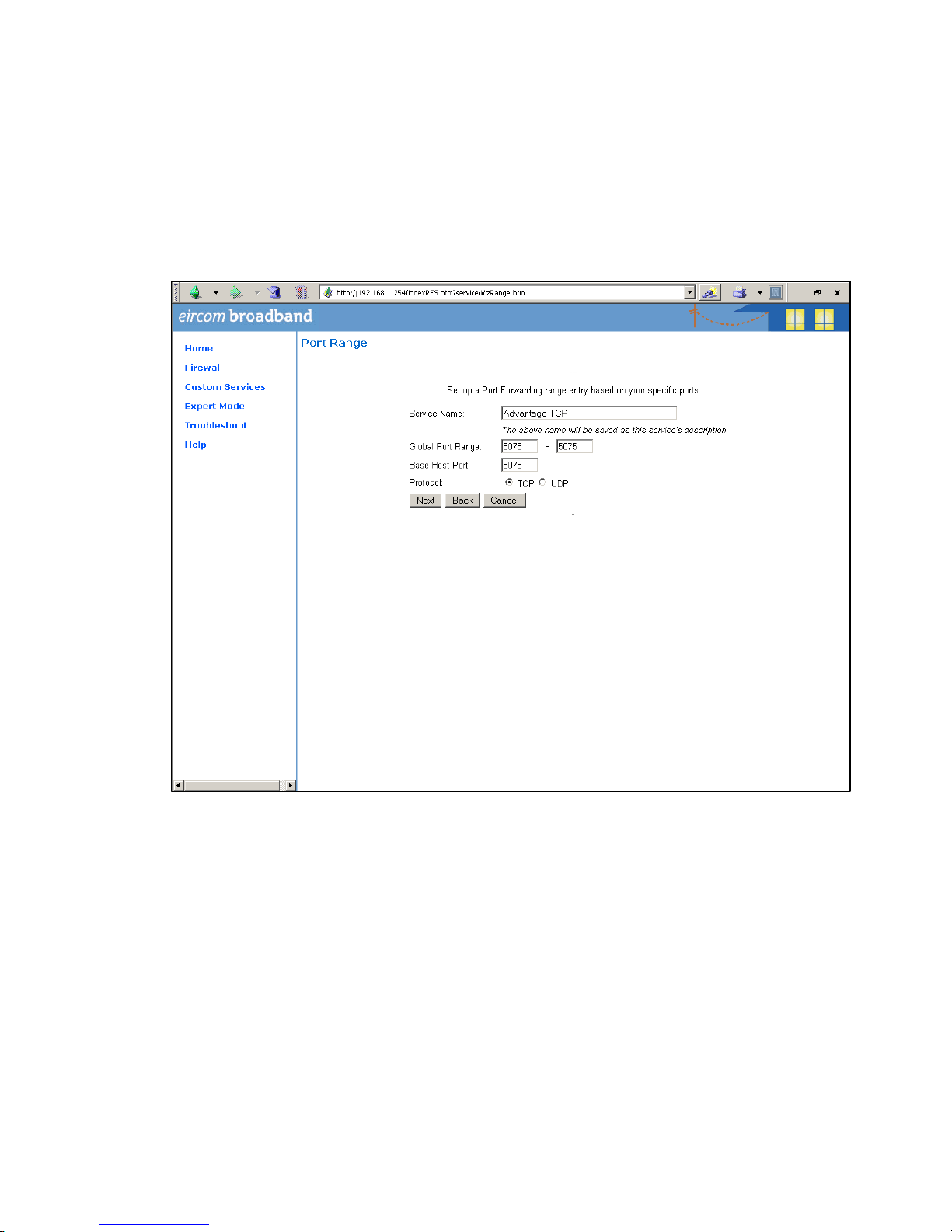
Advantage 2000 System Manual
DM 1030 Page 58
At the next screen type in the following information as shown:
Service Name: Advantage TCP
Global Port Range: 5075 - 5075
Base Host Port: 5075
Protocol: TCP
Press ‘Next’ and on the following screen press ‘Done’.

Advantage 2000 System Manual
DM 1030 Page 59
On the next screen, open the dropdown list and select the service ‘Advantage TCP’
which you have defined and press the button ‘Enable’.

Advantage 2000 System Manual
DM 1030 Page 60
The following screen is displayed:
In the dropdown box ‘Select Host Service’ choose the local LAN IP address of the
Advantage (here called Advantage) system.
Press ‘Enable’.

Advantage 2000 System Manual
DM 1030 Page 61
All TCP traffic on port 5075 will now be forwarded to the Advantage system (called
Advantage in this example) and this is recorded as shown on the following screen.

Advantage 2000 System Manual
DM 1030 Page 62
Step 4 Define port Forwarding for UDP
Press the button ‘Define Custom Service’ to display the following screen.
Select ‘Port Forwarding: Range of Ports’ and press ‘Next’.

Advantage 2000 System Manual
DM 1030 Page 63
Type in the following information on the next screen as shown:
Service Name: Advantage UDP
Global Port range: 50000 – 50031
Base Host Port: 50031
Protocol: UDP
Press ‘Next’ and on the following screen, press ‘Done’. The next screen is displayed.

Advantage 2000 System Manual
DM 1030 Page 64
Select ‘Advantage UDP’ from the drop down menu and press Enable.

Advantage 2000 System Manual
DM 1030 Page 65
In the following screen select the local LAN IP address of the Advantage (Advantage)
system in the box ‘Select Host Device’ and press ‘Enable’.

Advantage 2000 System Manual
DM 1030 Page 66
All UDP traffic on ports 50000 to 50031 will now be forwarded to the Advantage
(Advantage) system and this is recorded as shown on the next screen.
This completes the configuration of the Port Forwarding.

Advantage 2000 System Manual
DM 1030 Page 67
A
A
A
p
p
p
p
p
p
e
e
e
n
n
n
d
d
d
i
i
i
x
x
x
X
X
X
I
I
I
U
U
U
s
s
s
a
a
a
g
g
g
e
e
e
o
o
o
f
f
f
t
t
t
h
h
h
e
e
e
1
1
1
2
2
2
c
c
c
o
o
o
m
m
m
m
m
m
u
u
u
n
n
n
i
i
i
c
c
c
a
a
a
t
t
t
i
i
i
o
o
o
n
n
n
c
c
c
h
h
h
a
a
a
n
n
n
n
n
n
e
e
e
l
l
l
s
s
s
a
a
a
v
v
v
a
a
a
i
i
i
l
l
l
a
a
a
b
b
b
l
l
l
e
e
e
o
o
o
n
n
n
t
t
t
h
h
h
e
e
e
s
s
s
y
y
y
s
s
s
t
t
t
e
e
e
m
m
m
Channels used by devices
in communication, 12 max.
IP system phone on the LAN
IP system phone remote, WAN
Symbian SIP extension, WLAN
Analogue a/b extensions
SIP trunk
VoIP Networking channel
ISDN trunk channel
PSTN analogue trunk
Automated Attendant
Voice mail
IP system phone on the LAN 0 2 2 1 2 2 1 1 1 1
IP system phone remote,
WAN 2 2 2 1 2 2 1 1 1 1
Symbian SIP extension,
WLAN 2 2 2 1 2 2 1 1 1 1
Analogue a/b extensions 1 1 1 0 1 1 0 0 0 0
SIP trunk 2 2 2 1 2 2 1 1 1 1
VoIP Networking channel 2 2 2 1 2 2 1 1 1 1
ISDN trunk channel 1 1 1 0 1 1 0 0 0 0
PSTN analogue trunk 1 1 1 0 1 1 0 0 0 0
Automated Attendant 1 1 1 0 1 1 0 0 n/a n/a
Voice mail 1 1 1 0 1 1 0 0 n/a n/a
 Loading...