

Page 1

TM 11-6625-3031-14
.
TECHNICAL MANUAL
OPERATOR’S, ORGANIZATIONAL,
DIRECT SUPPORT,
AND
GENERAL SUPPORT MAINTENANCE MANUAL
COUNTER, PULSE, ELECTRONIC
TD-1338(V)1/USM
(NSN 6625-01-120-7832)
HEADQUARTERS, DEPARTMENT OF THE ARMY
6 MAY 1983
Page 2

SAFETY STEPS TO FOLLOW IF SOMEONE
IS THE VICTIM OF ELECTRICAL SHOCK
DO NOT TRY TO PULL OR GRAB THE INDI-
VIDUAL
IF POSSIBLE, TURN OFF THE ELECTRICAL
POWER
IF YOU CANNOT TURN OFF THE ELECTRICAL
POWER, PULL, PUSH, OR LIFT THE PERSON
TO SAFETY USING A WOODEN POLE OR A ROPE
OR SOME OTHER INSULATING MATERIAL
SEND FOR HELP AS SOON AS POSSIBLE
AFTER THE INJURED PERSON IS FREE OF CONTACT WITH THE SOURCE OF ELECTRICAL
SHOCK, MOVE THE PERSON A SHORT
DISTANCE AWAY AND IMMEDIATELY START
ARTIFICIAL RESUSCITATION
Page 3

TM 11-6625-3031-14
TECHNICAL MANUAL
NO. 11-6625-3031-14
REPORTING ERRORS AND RECOMMENDING IMPROVEMENTS
You can help improve this manual.
you know of a way to improve the procedures, please let us know.
Mail your letter,
tions and Blank Forms),
this manual direct to:
Electronics Command and Fort Monmouth, ATTN:
Fort Monmouth, NJ 07703.
DEPARTMENT OF THE ARMY
WASHINGTON, D.C. 6 May 1983
OPERATOR’S,
AND GENERAL SUPPORT MAINTENANCE MANUAL
ORGANIZATIONAL, DIRECT SUPPORT
FOR
COUNTER, PULSE, ELECTRONIC
TD-1338(V)1/USM
(NSN 6625-01-120-7832)
If you find any mistakes or if
DA Form 2028 (Recommended Changes to Publica-
or DA Form 2028-2 located in the back of
Commander, US Army Communications-
DRSEL-ME-MP,
HEADQUARTERS
Chapter
Section I.
In either case,
INTRODUCTION
1.
General Information . . . . . . . . . . . . . . .
Scope. . . . . . . . . . . . . . . . . . . . 1-1
Reports of maintenance forms, records and
reports. . . . . . . . . . . . . . . . . . . . . 1-2
Administrative storage . . . . . . . . . . . . . 1-3
Destruction of Army electronics materiel. . . . . 1-4
Reporting equipment improvement recommendations
(EIR'
S
). . . . . . . . . . . . . . . . . . . . . 1-5
Warranty information . . . . . . . . . . . . . . 1-6
II.
Equipment Description . . . . . . . . . . . . . .
Equipment characteristics, capabilities and
features . . . . . . . . . . . . . . . . . . . . 1-7
Equipment data . . . . . . . . . . . . . . . . . 1-8
III.
Technical Principles of Operation . . . . . . . .
Counter functional operation . . . . . . . . . . 1-9
a reply will be furnished direct to you.
TABLE OF CONTENTS
Para
Page
1-1
1-1
1-1
1-1
1-1
1-1
1-1
1-2
1-2
1-2
1-4
1-4
i
Page 4

TM 11-6625-3031-14
TABLE OF CONTENTS - Continued
Chapter
Section I.
2.
II.
III.
Para
Basic counter A1 . . . . . . . . . . . . . ...1-10
Converter A2 . . . . . . . . . . . . . . . . . . 1-11
OPERATING INSTRUCTIONS
Description and Use of Operator’s Controls and
Indicators . . . . . . . . . . . . . . . . . . .
Front-panel controls, connectors and
indicators . . . . . . . . . . . . . . . . . . .
Rear-panel controls and connectors. . . . . . . .
Preventive Maintenance Checks and Services . . .
General instructions. . . . . . . . . . . . . . .
PMCS procedures. . . . . . . . . . . . . . . . .
Cleaning instructions . . . . . . . . . . . . . .
Operation Under Usual Conditions . . . . . . . .
Assembly and preparation for use . . . . . . . .
Operation as stand-alone instrument . . . . . . .
Externally enabled operation . . . . . . . . . .
Pulse profile measurements. . . . . . . . . . . .
Dynamic characteristics of time varying signals .
Multiple pulse signal measurements . . . . . . .
Timing considerations . . . . . . . . . . . . . .
Accuracy . . . . . . . . . . . . . . . . . . . .
Techniques for improving accuracy . . . . . . . .
Operation using General Purpose Interface Bus . .
2-1
2-2
2-3
2-4
2-5
2-6
2-7
2-8
2-9
2-10
2-11
2-12
2-13
2-14
2-15
Page
1-6
1-8
2-1
2-1
2-1
2-5
2-5
2-5
2-6
2-7
2-7
2-8
2-10
2-10
2-11
2-11
2-11
2-12
2-13
2-13
Chapter
Section I. Lubrication . . . . . . . . . . . . . .
III. Maintenance Procedures . . . . . . . . . . . . . . . . .
Chapter
Section I.
III.
OPERATOR AND ORGANIZATIONAL
3.
II.
Troubleshooting Procedures . . . . . . . . . .
Introduction . . . . . . . . . . . . . . . . . . . . . . .
Inspection. . . . . . . . . . . . . . . . . . . . . . . .
Cleaning . . . . . . . . . . . . . . . . . . . . . . . . .
Replacement . . . . . . . . . . . . . . . . . . . . . . .
Test. . . . . . . . . . . . . . . . . . . . . . . . .
4.
DIRECT SUPPORT AND GENERAL SUPPORT MAINTENANCE
Repair Parts, Special Tools; Test Measurement,
and Diagnostic Equipment (TMDE); and Support
Equipment. . . . . . . . . . . . . . . . . . . . . . . . .
Common tools and equipment . . . . . . . . . .
Special tools, TMDE,
Repair parts . . . . . . . . . . . . . . . . . . . . . .
II.
Service Upon Receipt . . . . . . . . . . . . .
Troubleshooting . . . . . . . . . . . . . . . . . . . . .
Introduction . . . . . . . . . . . . . . . . . . .
Reference diagrams . . . . . . . . . . . . . .
IV.
Maintenance Procedures . . . . . . . . . . . .
Disassembly, replacement, and reassembly . . .
Adjustments. . . . . . . . . . . . . . . . . .
Performance test . . . . . . . . . . . . . . . . .
and support equipment . .
MAINTENANCE
3-4
3-5
3-6
3-7
3-8
4-1
4-2
4-3
4-5
4-6
4-7
4-8
4-9
3-1
3-1
3-3
3-3
3-3
3-3
3-3
3-3
4-1
4-1
4-1
4-1
4-1
4-1
4-1
4-2
4-17
4-17
4-20
4-28
ii
Page 5

TABLE OF CONTENTS - Continued
TM 11-6625-3031-14
Section
Preparation for Storage or Shipment . . . . . . .
V.
Preparation of equipment. . . . . . . . . . . . . 4-10
Packing instructions. . . . . . . . . . . . . . . 4-11
Appendix A. REFERENCES. . . . . . . . . . . . . . . . . . . .
Appendix B.
Appendix C.
MAINTENANCE ALLOCATION . . . . . . . . . . . . .
COMPONENTS OF END ITEM AND BASIC ISSUE
ITEMS LISTS. . . . . . . . . . . . . . . . . . .
Appendix D.
Appendix E.
ADDITIONAL AUTHORIZATION LIST . . . . . . . . . .
EXPENDABLE SUPPLIES AND MATERIALS LIST . . . . .
Para
Page
4-33
4-33
4-33
A-1
B-1
C-1
D-1
E-1
iii
Page 6

TM 11-6625-3031-14
LlST OF ILLUSTRATIONS
Figure
1-1
1-2
1-3
1-4
2-1
2-2
2-3
2-4
2-5
2-6
2-7
2-8
4-1
4-2
4-3
4-4
4-5
4-6
4-7
4-8
4-9
4-10
4-11
4-12
Title
Counter,
Counter,
Basic Counter A1,
Converter A2, Functional Block Diagram . . . . . . . . . . . . . . 1-9
Counter Front Panel. . . . . . . . . . . . . . . . . . . . . . . .2-1
Counter Rear Panel. . . . . . . . . . . . . . . . . . . . . . . .2-4
Pulse Profile Measurement Test Setup . . . . . . . . . . . . . . . 2-10
Pulse Profile Measurement . . . . . . . . . . . . . . . . . . . . 2-10
Time Varying Signal Measurement Test Setup . . . . . . . . . . . . 2-11
Internal Timing Delays . . . . . . . . . . . . . . . . . . . . . . 2-12
GPIB Capabilities and Structure . . . . . . . . . . . . . . . . . 2-15
GPIB IEEE STD 488/1975 ADDRESS SWITCH Positions . . . . . . . . . 2-16
Subassembly and Cable Locations . . . . . . . . . . . . . . . . . 4-3
Counter Interconnect A100, Connector and Switch Locations . . . . 4-17
Counter, Partial Exploded View . . . . . . . . . . . . . . . . . . 4-18
Adjustment Locations. . . . . . . . . . . . . . . . . . . . . . . 4-21
Pulse Generator Output . . . . . . . . . . . . . . . . . . . . . . 4-23
YIG Control A202, Adjustment and Test Point Locations . . . . . . 4-24
Detected Modulation and 20 kHz Reference Pulse Timing . . . . . . 4-24
Converter Sequencer A203, Adjustment and Test Point
Locations. . . . . . . . . . . . . . . . . . . . . . . . . . . . .4-26
Return Loss Measurement Setup . . . . . . . . . . . . . . . . . . 4-26
Return Loss Measurement Waveform . . . . . . . . . . . . . . . . . 4-27
Typical Attenuator Control Ramp Offset . . . . . . . . . . . . . . 4-27
Comb Line . . . . . . . . . . . . . . . . . . . . . . . . . . . .4-27
Pulse, Electronic TD-1338(V)1/USM . . . . . . . . . . . . 1-0
Functional Block Diagram. . . . . . . . . . . . . . . . . 1-5
Functional Block Diagram . . . . . . . . . . . . 1-7
Page
FO-1
FO-2
FO-3A
FO-3B
FO-4A
FO-4B
FO-5A
FO-5B
FO-6A
FO-6B
FO-7A
FO-7B
FO-8A
FO-8B
FO-9A
FO-9B
FO-10A
FO-10B
iv
Counter Interconnection Schematic Diagram
Interconnection Diagram,
Component Locator Counter Interconnect (A100)
Schematic Diagram Counter Interconnect (A100)
Component Locator and Descriptive Information Count Chain Control (A102)
Schematic Diagram Count Chain Control (A102)
Component Locator and Descriptive Information Count Chain (A103)
Schematic Diagram Count Chain (A103)
Component Locator and Descriptive Information Control (A104)
Schematic Diagram Control (A104)
Component Locator and Descriptive Information Gate Generator (A105)
Schematic Diagram Gate Generator (A105)
Component Locator and Descriptive Information High Frequency (A106)
Schematic Diagram High Frequency (A106)
Component Locator and Descriptive Information Power Supply (A107)
Schematic Diagram Power Supply (A107)
Component Locator and Descriptive Information Reference Oscillator
Buffer (A108)
Schematic Diagram Reference Oscillator Buffer (A108)
Detailed Technical Schematic
Page 7

TM 11-6625-3031-14
Figure
FO-11A
FO-11B
FO-12A
FO-12B
FO-13A
FO-13B
FO-14A
FO-14B
FO-15A
FO-15B
FO-16A
FO-16B
LIST OF ILLUSTRATIONS
Title
Component Locator and Descriptive Information Display (A110)
Schematic Diagram Display (A110)
Component Locator Converter Interconnect (A200)
Schematic Diagram Converter Interconnect (A200)
Component Locator and Descriptive Information Source/Amplifier (A201)
Schematic Diagram Source/Amplifier (A201)
Component Locator and Descriptive Information Yig Control (A202)
Schematic Diagram Yig Control (A202)
Component Locator and Descriptive Information Converter Sequencer (A203)
Schematic Diagram Converter Sequencer (A203)
Component Locator and Descriptive Information IF Processor (A204)
Schematic Diagram IF Processor (A204)
(Continued)
Table
1-1
2-1
2-2
2-3
2-4
2-5
2-6
2-7
2-8
2-9
3-1
4-1
4-2
4-3
4-4
4-5
4-6
4-7
LIST OF TABLES
Title
Specifications. . . . . . . . . . . . . . . . . . . . . . . . . .
Front-panel Controls, Connectors and Indicators . . . . . . . . .
Rear-panel Controls and Connectors . . . . . . . . . . . . . . . .
Operator Preventive Maintenance Checks and Services . . . . . . .
Counter GPIB Capability Identification Codes . . . . . . . . . . .
GPIB IEEE STD 488/1975 Connector Pin Assignments . . . . . . . . .
On Line and Off Line ADDRESS SWITCH Settings . . . . . . . . . . .
ADDRESS SWITCH Settings vs ASCII Characters . . . . . . . . . . .
Programming Summary. . . . . . . . . . . . . . . . . . . . . . . .
Typical Program Using Hewlett-Packard 9815 Calculator as
Controller. . . . . . . . . . . . . . . . . . . . . . . . . . . .
Operator and Organizational Troubleshooting . . . . . . . . . . .
Symptom Index . . . . . . . . . . . . . . . . . . . . . . . . . .
Direct Support and General Support Troubleshooting . . . . . . . .
Power Supply Voltages and Adjustments . . . . . . . . . . . . . .
Band B Response Tests . . . . . . . . . . . . . . . . . . . . . .
Preset Frequency Tests . . . . . . . . . . . . . . . . . . . . . .
Control Sequence. . . . . . . . . . . . . . . . . , . . . . . , .
Converter Sequence Functions . . . . . . . . . . . . . . . . . . .
Page
1-1
2-1
2-5
2-6
2-14
2-16
2-17
2-18
2-20
2-26
3-1
4-2
4-4
4-22
4-29
4-31
4-45
4-65
v
Page 8
TM 11-6625-3031-14
1-0
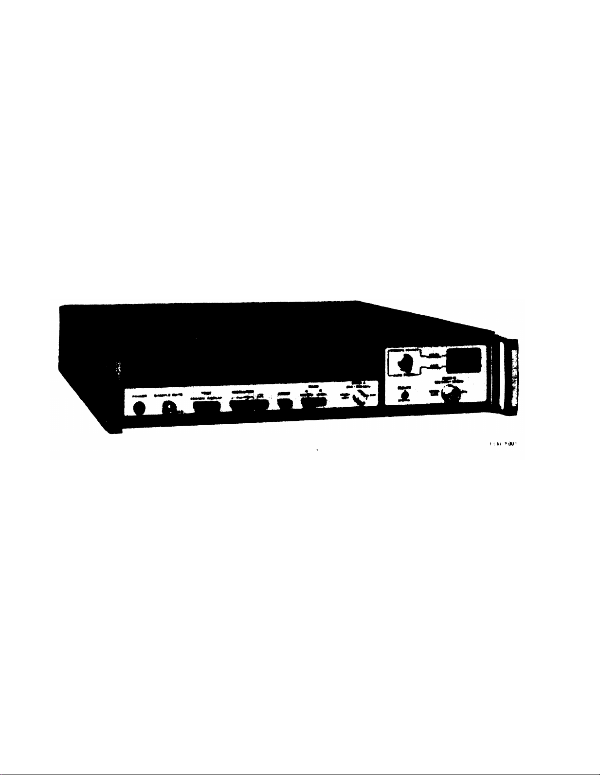
Figure 1-1.
Counter, Pulse, Electronic TD-1338(V)1/USM
Page 9

CHAPTER 1
INTRODUCTION
Section I. GENERAL INFORMATION
TM 11-6625-3031-14
1-1.
tion and maintenance of Counter, Pulse,
Electronic TD-1338(V)1/USM. Throughout
this manual it is referred to as the
counter.
measure the frequency of cw, pulsemodulated, or frequency-modulated
microwave signals between 300 MHz and
18 GHz.
as 100 nanoseconds, with a maximum
pulse repetition frequency of 2.5 MHz.
Peak-to-peak deviation of FM signals
may be as great as 40 MHz at 10 MHz
modulation rates.
1-2.
Records and Reports.
Unsatisfactory Equipment.
of the Army forms and procedures used
for equipment maintenance will be
those prescribed by TM 38-750, The
Army Maintenance Management System
(Army) .
AFM 66-1 for maintenance reporting and
TO 00-35D54 for unsatisfactory equipment reporting.
Deficiencies.
SF 364 (Report of Discrepancy (ROD)) as
prescribed in AR 735-11-2/DLAR 4140.55/
NAVMATINST 4355.73/AFR 400-54/MCO
4430.3E.
(DISREP) (SF 361). Fill out and forward
Discrepancy in Shipment Report (DISREP)
(SF 361) as prescribed in AR 55-38/
NAVSUPINST 4610.33B/AFR 75-18/MCO
P4610.19C/DLAR 4500.15.
Scope.
a. This technical manual covers opera-
b. The counter (fig. 1-1) is used to
Pulse widths can be as narrow
Reports of Maintenance Forms,
a. Reports of Maintenance and
Department
Air Force personnel will use
b. Report of Packaging and Handling
Fill out and forward
c. Discrepancy in Shipment Record
1-3.
issued to and used by Army activities
will have preventive maintenance per-
formed in accordance with the PMCS
charts before storing.
the equipment from administrative
storage, the PMCS should be performed
to assure operational readiness.
1-4.
Materiel.
materiel to prevent enemy use shall be
in accordance with TM 750-244-2.
1-5.
Recommendations (EIR’s).
let us know.
user,
what you don’t like about your equipment.
the design or performance.
SF 368 (Quality Deficiency Report).
Mail it to:
Communications-Electronics Command and
Fort Monmouth, ATTN: DRSEL-ME-MP,
Fort Monmouth, New Jersey 07703. We’ll
send you a reply.
1-6.
Microwave, Inc. for 12 months. It
starts on the date, found in block 23,
DA Form 2408-9, in the logbook.
all defects in material or workmanship
to your supervisor, who will take appropriate action through your organizational maintenance shop.
Administrative Storage.
Administrative storage of equipment
When removing
Destruction of Army Electronics
Destruction of Army electronics
Reporting Equipment Improvement
If your counter needs improvement,
Send us an EIR. You, the
are the only one who can tell us
Let us know why you don’t like
Put it on an
Commander, US Army
Warranty Information.
The counter is warranted by EIP
Report
1-1
Page 10
TM 11-6625-3031-14
Section II. EQUIPMENT DESCRIPTION
1-7.
Equipment Characteristics, Capa-
bilities and Features.
The counter is a portable test
instrument usable as either selfcontained frequency measurement or
monitoring indicator, or as part of a
programmable automatic test equipment
(ATE) system.
readout of frequency from 300
through 18 MHz.
It provides a direct
MHZ
Capabilities and
features include:
a. Measures pulse-modulated microwave
signals.
b. Measures frequency-modulated
microwave signals.
c.
Measures cw microwave signals.
d. Front panel self-test of digital
display.
Table 1-1. Specifications
Frequency Range:
Band A
e. Front panel self-test of internal
circuits.
f. Automatic and selectable resolution
of—readout display.
g. Overload protection built in at
input connector.
h.
Simple change to cover different
power line voltages.
i. Front-panel selection of frequency
scanning limits.
j. Comparable with IEEE STD 488
General Purpose Interface Bus (GPIB).
1-8.
Equipment Data.
Table 1-1 lists the electrical
and physical characteristics of the
counter.
300 MHz to 950 MHz
Band B
Pulse Characteristics:
Pulse width
Pulse repetition frequency
Accuracy:
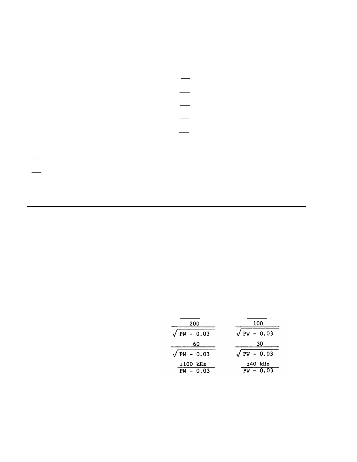
CW or pulse > 100 µsec
Pulse < 100 µsec
Averaging Error (kHz rms):
100 µsec gate
1 msec gate
Gate error (max)
925 MHz to 18 GHz
100 nsec min, measured at 3-dB points
Minimum 50 Hz or 0 Hz, rear panel
selectable. Maximum 2.5 MHz. Minimum
time between pulses 300 nsec.
Time base accuracy ± 1 count
Time base accuracy ± averaging error
± gate error
Band A Band B
NOTE
PW =
pulse width in µsec
1-2
Page 11

TM 11-6625-3031-14
Table 1-1.
Time Base:
Crystal frequency
Stability:
Aging rate
Temperature
Line voltage
Sensitivity
Input Impedance
Connector Types
Maximum Input Peak Level:
Operating
Burnout level
Specifications - Continued
Temperature compensated crystal
oscillator
(TCXO)
10 MHz
<|3 X 10
<|2 X 10
<|1 X 10
-7
|
per month
-6
|
, 0 to 50°C
-7
|
for ± 10% change
Band A
300
- 950 MHz:
-10 dBm peak
50 ohms nominal
BNC
+10 dBm
+27 dBm
Band B
925 MHz - 10 GHz:
-10 dBm peak
10 GHz - 18 GHz:
-5 dBm peak
50 ohms nominal
N (precision)
+10 dBm
+30 dBm
Reading Time (sec):
100 µsec gate
1 msec gate
Display
Band B Minimum FM Tolerance:
CW
Pulse
Frequency profile
400
(PW) (PRF)
4000
(PW)(PRF)
100
(PW) (PRF)
1000
(PW) (PRF)
NOTE
PW =
PRF =
pulse width in µsec
pulse repetition frequency
in Hertz
7-digit light emitting diode (LED)
Fixed decimal point
Leading zero suppression
40 MHz p-p deviation for modulation
rates dc to 10 MHz
Without input inhibit:
20 MHz maximum
frequency shift across pulse
With input inhibit:
20 MHz maximum
frequency shift during input inhibit
pulse
1-3
Page 12

TM 11-6625-3031-14
Table 1-1.
Specifications - Continued
Band B Acquisition Time:
PRF > 100 H
Z
PRF < 100 Hz
Resolution
General Purpose Interface Bus (GPIB)
Power
Operating Temperature
Warm up Time
Weight
Dimensions (inches)
100 msec + 50 msec/GHz
100 msec +
sec/GHz
10 kHz, 100 kHz, 1 MHz
IEEE Standard Digital Interface for
Programmable Instrumentation, IEEE
STD 488-1975
115 or 230 Vac ± 10%, 50/60 Hz;
115 Vac ± 10%, 400 Hz; single phase;
100 watts nominal
0-
50°C
None Required
30 lb
3.5 H x 16.75 W x 19.0 D
Section Ill. TECHNICAL PRINCIPLES OF OPERATION
1-9.
Counter Functional Operation.
(Fig. 1-2.)
a. The counter automatically measures
and displays the frequency of cw or
pulse-modulated signals from 300 MHz
through 18 GHz. With accessory equip-
ment,
the counter can make dynamic
frequency measurements; measurement
windows as narrow as 20 nanoseconds are
possible.
Two primary input connectors
on the front panel, BAND A 300 - 950 MHz
and BAND B 925 MHz - 18 GHz, are used to
connect the counter to the external frequency source.
An auxiliary INPUT
INHIBIT connector on the rear panel can
be used to control the time during
which an actual reading is made.
Control of the counter can be accomplished
by front-panel switches or by a General
Purpose Interface Bus (GPIB) from an
external GPIB controller.
The output
of the counter is displayed on a 7digit, fixed decimal, light emitting
diode (LED) display and can be transmitted through the GPIB for other
purposes.
controlled by Reference Oscillator Buffer A108 with outputs to Basic Counter
Al and Converter A2; a third output is
connected to a rear-panel 10 MHz OUTPUT
connector.
divide-by-four circuit in Prescaler
A109, whose output is directed to Basic
Counter A1 through Dual Delay Line
A116.
counted in the basic counter for either
a 400 microsecond or 4 millisecond
period to obtain 10 kHz resolution readout on Display A110.
in A1 is enabled by the input signal and
is open only when a signal is present.
verter A2, converted to an IF signal by
heterodyning the input signal against a
200 MHz harmonic,
through Delay Line A112.
gate in A1 is enabled by the Input
signal and is open only when a signal
is present.
inversely proportional to the measurement
Accuracy of the counter is
Band A signals are fed into a
b.
The divide-by-four frequency is
The counter gate
Band B signals are fed into Con-
c.
and directed to A1
The counter
In A1, resolution is
1-4
Page 13
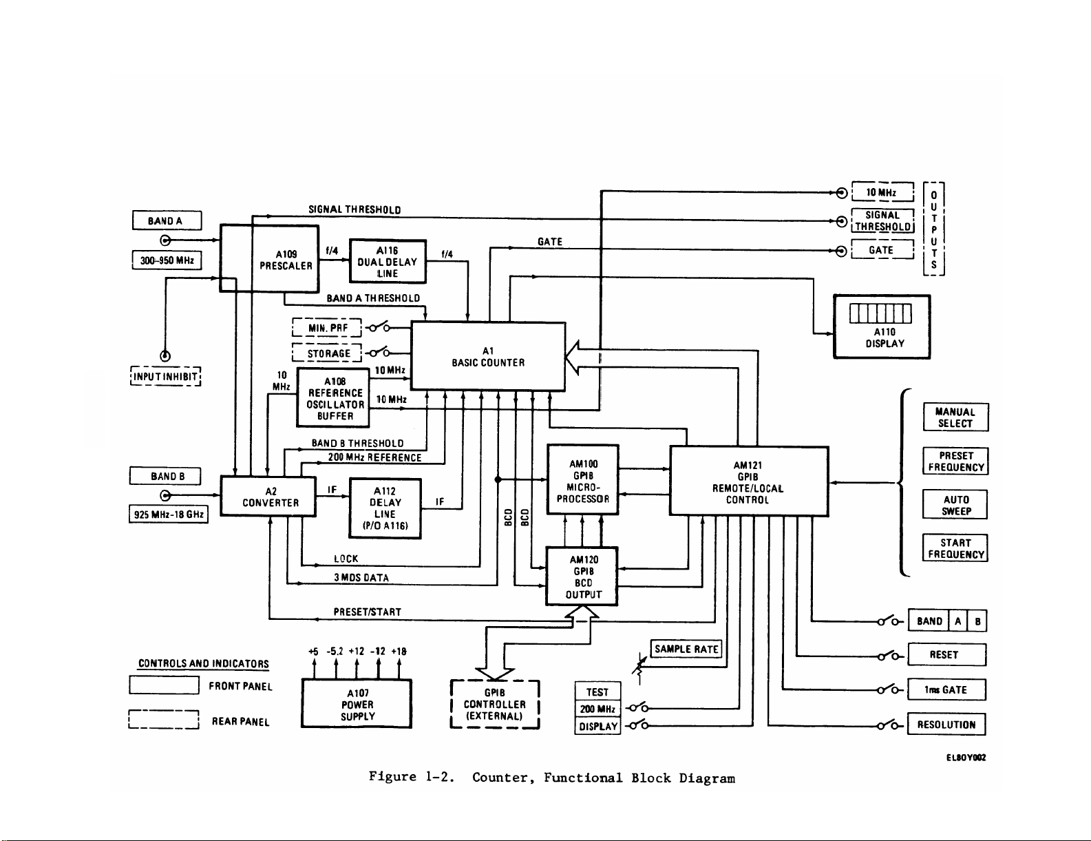
Figure 1-2.
1-5
TM 11-6625-3031-14
Page 14

TM 11-6625-3031-14
time.
For example:
a 1 microsecond
gate time will give 1 MHz resolution.
To get 10 kHz resolution, the counter
threshold comes from Prescaler A109
while the Band B threshold comes from
I.F. Processor A204 in Converter A2.
automatically averages as many input
pulses as necessary to obtain a total
gate time of 100 microseconds or 1 millisecond.
The required number of
pulses is a function of input pulse
width.
The intermediate frequency from
A2 is processed and counted in A1 and
displayed on A110.
d.
Three rear-panel connectors provide
10–MHz, SIGNAL THRESHOLD, and GATE OUT-
PUTS .
The 10 MHz OUTPUT is a service
convenience for adjusting the temperature compensated crystal oscillator
(TCXO) on Reference Oscillator Buffer
A108.
The other two signal outputs may
be used for dynamic frequency measurements such as pulse profile measurements
or time varying signal measurements.
e.
Power Supply A107 provides +5,
-5.2, +12,
counter circuits.
-12, and +18 volts dc for the
The +18 Vdc output is
unregulated; the other four voltages are
regulated.
processed into the range below 360 MH
and applied to the 400 MHz decade, the
frequency of the signal is determined by
accumulating the number of signal cycles
occurring within a precisely determined
time interval (gate). The gate period
is dependent on the 200 MHz reference
frequency.
gates are 100 microseconds and 1 milli-
second for Band B, or 400 microseconds
and 4 milliseconds for Band A. In order
to measure narrow pulses to a resolution
of 10 kHz, it is necessary to add the
number of cycles counted in each of a
large number of pulses until the
required total time interval is
obtained.
precision interval gate. This function
is considerably more difficult for
pulsed signals than it is for cw signals,
the overall accuracy of the counter
1-10.
Basic Counter A1.
(Fig. 1-3.)
depends.
it supplies a gate to A106 only when an
a. Input signals from either the low
range (300 -
(925 MHz -
950 MHz) or high range
18 GHz) sources, or both,
are applied to the signal processor
circuits on High Frequency Circuit
Card A106.
The signal from Prescaler
input signal is present, and it accumulates the total time of gate application
for periods of either 100 microseconds
or 1 millisecond for Band B, or either
400 microseconds or 4 milliseconds for
Band A.
A109 is the BAND A input frequency,
divided by four (f/4). The signal
from I.F. Processor A204 is the BAND B
input frequency minus the reference
frequency identified as the converter
IF signal.
Selection of which signal
to display is controlled by the front
panel BAND selection switches or by
GPIB selection.
Only one of the signal
inputs can be displayed even though
both may be connected to the counter.
The f/4 and the IF signal inputs are
360 MHz or lower and are directed to the
400 MHz decade circuits on A106.
Two threshold (Band A and/or
b.
Band B) control levels are applied to
Gate Generator A105 to provide a gate
output to the 400 MHz decade through
the gate calibrator.
The Band A
requires that the gate begin after the
signal is present at A106 and to end
before the end of signal. This is done
by generating a gate approximately 30
nanoseconds shorter than the RF signal
start as determined by the associated
Band A or Band B threshold level.
arrival time at A106 of the converter
IF or the prescaler f/4 signal is con-
trolled by delay lines in A116, in
series with the signals, so that the
gate will fall entirely within the signal pulse application.
counting clock pulses when the gate is
open until a total period of 100 micro-
seconds or 1 millisecond for Band B, or
400 microseconds or 4 milliseconds for
When an input signal has been
c.
Z
Total time intervals of the
d. Gate Generator A105 provides a
and it is on this function that
A105 performs two functions;
e. The first function or operation
The
f. The second function is done by
1-6
Page 15
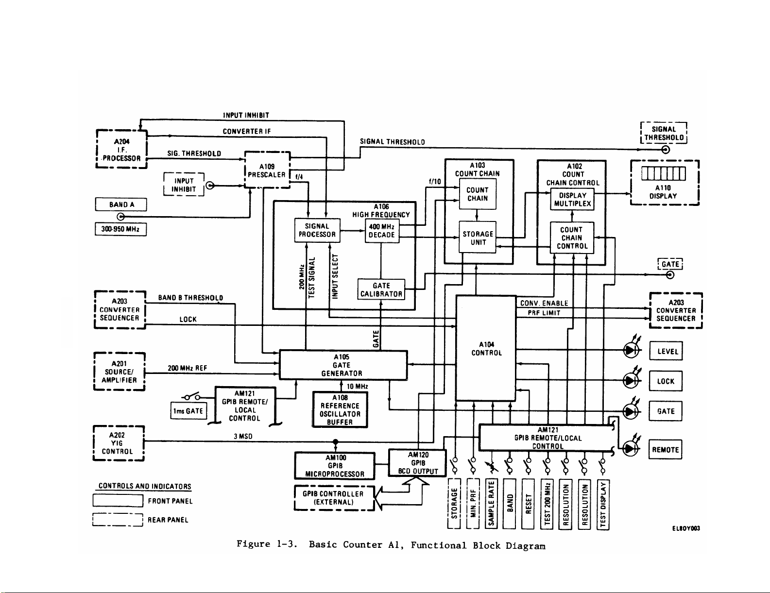
Figure 1-3.
1-7
TM 11-6625-3031-14
Page 16

TM 11-6625-3031-14
Band A, is accumulated.
that each gate opening is for an exact
integral number of clock pulses.
MHz clock is used, causing the gate
width to increase in 5 nanosecond steps
until a total of 20,000 steps for
100 microseconds, 80,000 steps for
400 microseconds, 200,000 steps for
1 millisecond, or 800,000 steps for
4 milliseconds is accumulated.
g. The signal passes through the
counter gate and is accumulated in the
counting-chain first decade, the 400
MHz decade on A106.
(f/10) of the 400 MHz decade is fed to
the storage unit through the 6-decade
count chain of A103. The storage unit
on A103 holds all of the digital information from the previous reading.
put from the storage unit is fed to the
display multiplexer which is controlled
by count chain control circuits on the
Count Chain Control A102.
h. Output of the display multiplexer
on A102 is fed to Display A110.
mounted on the front panel along with
LEVEL, LOCK, and GATE status indicators.
The front-panel REMOTE indicator is used
with GPIB controller operations.
all control of the counter is performed
by Control Circuit Card A104. Frontpanel selection switching is routed to
A104 through GPIB Remote/Local Circuit
Card AM121.
REMOTE mode of operation, front-panel
controls and switches are inoperative
except for the SAMPLE RATE control, and
then only under certain programming
instructions from the GPIB controller.
1-11.
input microwave frequencies down to
frequencies between 100 and 360 MHz.
Translation is done by mixing the input
frequencies with a reference frequency
to produce, by heterodyne action, an
amplified intermediate frequency.
IF is then fed to A106 through Delay
Line A112 for counting and processing in
Basic Counter A1.
b. Generation of the heterodyning ref-
erence frequency starts by generating a
Converter A2.
a. Converter A2 translates the Band B
When the counter is in the
This requires
A 200
The signal output
Out-
A110 is
Over-
(Fig. 1-4.)
The
200 MHz reference signal in Source/
Amplifier A201. The 200 MHz reference
in A201 is generated by an L-C oscilla-
tor phase-locked to 10 MHz from Reference Oscillator Buffer A108.
MHz outputs from A201 are directed to
YIG (Yttrium-Iron-Garnet) Comb Generator
A207 and to Gate Generator A105 in
Basic Counter A1.
section on A201 amplifies the 200 MHz
signal before it is applied to A207.
The 200 MHz output to A105 is used to
generate a Band B gate or may be used
for a TEST 200 MHz self-test.
harmonic, frequency is generated in YIG
Comb Generator A207 by taking the 200
MHz signal from A201 and converting it
to a train of narrow pulses containing
all harmonics of 200 MHz up to 18 GHz.
This conversion is done by the YIG comb
generator and a two-stage YIG filter,
which selects the desired 200 MHz
harmonic. The YIG filter is tuned by
varying the current through a pair of
coils, which change magnetic fields in
the assembly.
to Limiter/Attenuator A206.
diode limiter protects Mixer A205 from
power levels in excess of one watt peak
(+30 dBm).
diode attenuator section controls the
RF signal level to the mixer and
switches off the input signal during
portions of converter operation.
wave circuit assembly consisting of a
hybrid coupler, termination, mixer
diode, and dc return. The mixer produces two output signals on a common
line:
ence frequency between the incoming RF
signal from A206 and the reference frequency harmonic from A207, and a video
signal resulting from rectification
(detection) of either the RF or reference inputs. The mixer output is fed to
I.F. Processor A204.
A205 are separated in A204. The IF signal is amplified by the IF amplifier and
sent on as the converter IF signal to
A106, through Delay Line A112, for
The 200
A power amplifier
c.
The local oscillator, or reference
d. Band B input signals are applied
A passive
A multistage matched PIN
e.
Mixer A205 is an integrated micro-
an IF signal equal to the differ-
f. The IF and video signals from Mixer
1-8
Page 17
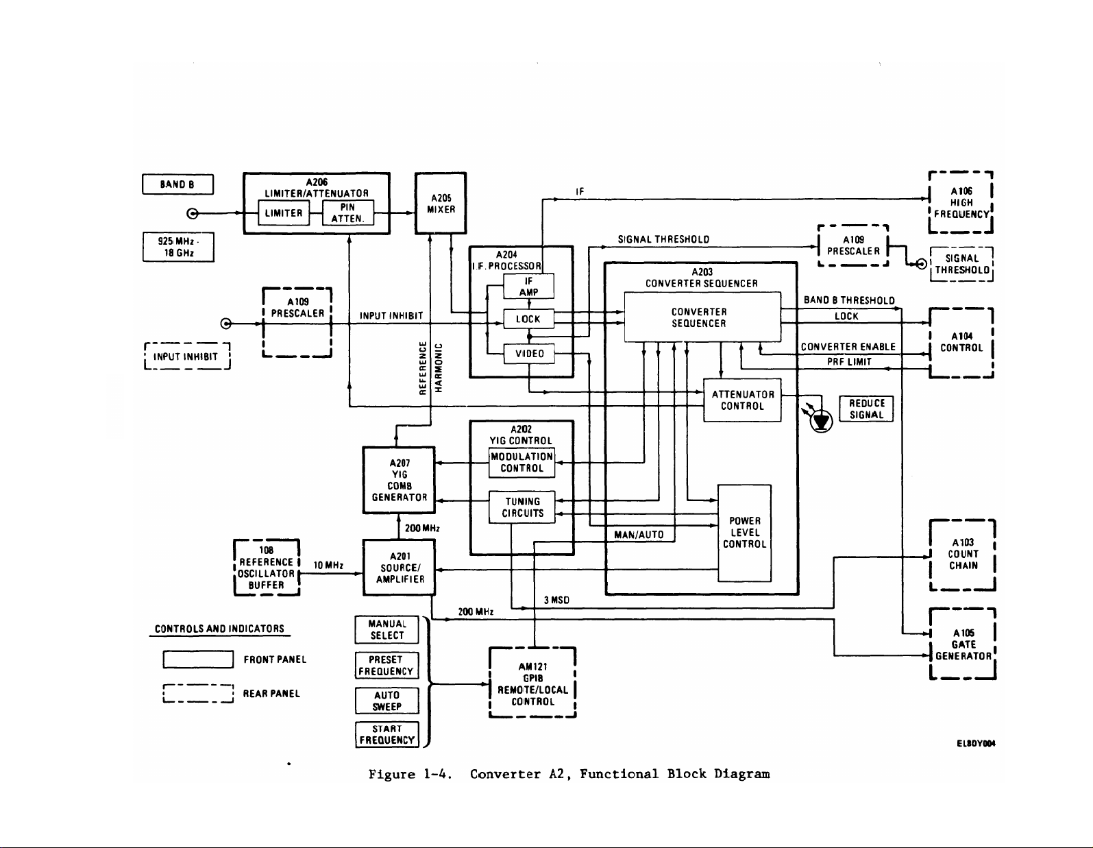
Figure 1-4.
1-9
TM 11-6625-3031-14
Page 18

TM 11-6625-3031-14
counting.
The video signal is amplified
in the video amplifier to produce three
video outputs: (1) a threshold signal
is directed to the rear-panel SIGNAL
THRESHOLD connector through Prescaler
A109;
(2) a threshold signal, identified as attenuator control, is sent to
an attenuator control circuit on Con-
verter Sequencer A203; and
(3) an
analog output is applied to the power
level control portion of A203.
g.
On A203, inputs from the lock
section of I.F. Processor A204 are
sequenced and timed to produce a lock
level signal for Control A104 and a
Band B threshold signal for Gate Gen-
erator A105.
The attenuator control
threshold signal from the video section
of A204 is combined with an input from
the converter sequencer in the attenu-
ator control to give two outputs:
(1) an attenuator control signal, activated at a level approximately 7 dB
above signal threshold, sent to the PIN
attenuator of A206, to reduce signal
level into Mixer A205; and (2) a reduce
signal level sent to the front-panel
REDUCE SIGNAL indicator when the
attenuator control is sending a signal
to the PIN attenuator.
The power level
control circuit receives an analog input
from the video section of A204 and a
digital signal from the converter
sequencer of A203, and provides a signal
to the tuning circuits of A202 to set
the comb line amplitude.
The converter
sequencer function is to control the
sensing, leveling, and control of Converter A2.
YIG Control A202 contains circuits
h.
to step the YIG filter to the proper
comb line, and is controlled by input
lines from Converter Sequencer A204.
On-board circuits include a YIG driver
to supply the required current, a
digital-to-analog converter (DAC) to set
the approximate center frequency, and a
centering circuit to precisely center
the YIG filter passband on a comb line.
The centering process is done by modulating the YIG center frequency by an
auxiliary modulation coil in YIG Comb
Generator A207.
The modulation control
circuit is on A202.
1-10
Page 19
TM 11-6625-3031-14
CHAPTER 2
OPERATING INSTRUCTIONS
Section I. DESCRIPTION AND USE OF OPERATORS CONTROLS
AND INDICATORS
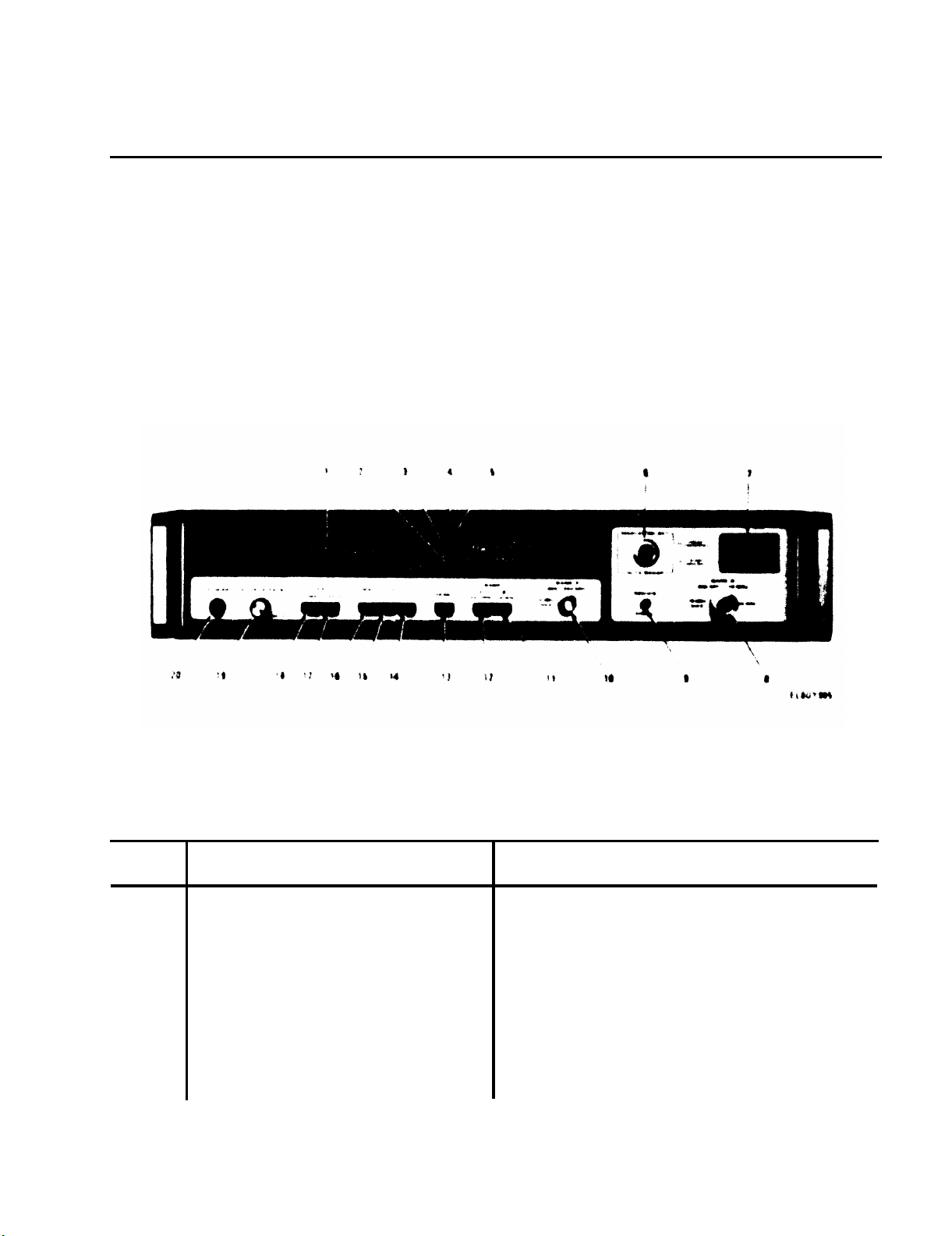
2-1.
and Indicators.
nectors and indicators are shown in fig-
ure 2-1 and are keyed to table 2-1,
which describes their functions.
Front-Panel Controls, Connectors
Operator’s front-panel controls, con-
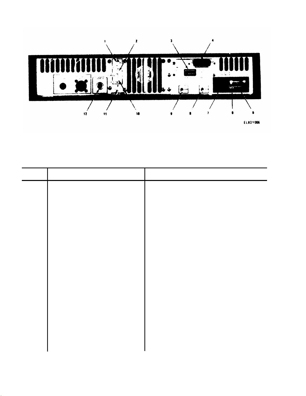
2-2.
Connectors.
connectors are shown in figure 2-2 and
are keyed to table 2-2, which describes
their functions.
Rear-panel Controls and
Operator’s rear-panel controls and
Key
1
2
Figure 2-1.
Table 2-1.
Control, connector
or indicator
Display
REMOTE indicator
Front-panel Controls,
Counter Front Panel
Connectors and Indicators
Functional operation
Seven-digit LED display provides
direct numerical readout of input
frequency in GHz and MHz.
When lighted, indicates that all
front-panel controls are disabled
except SAMPLE RATE. This indicator
is controlled by digital programmed
data on the General Purpose Interface Bus (GPIB) and by rear-panel
ADDRESS SWITCH.
2-1
Page 20

TM 11-6625-3031-14
Table 2-1.
Key
3
4
5
6
7
Front-panel Controls,
Control, connector
or indicator
GATE indicator
LEVEL indicator
LOCK indicator
MANUAL SELECT/AUTO SWEEP
switch
PRESET FREQUENCY/START
FREQUENCY thumbwheel
switch
Connectors and Indicators - Continued
Functional operation
Lights when counter is in measurement portion of cycle.
Lights when input signal level is
high enough to be counted. Light
will blink if signal pulse repeti-
tion frequency is too low.
Lights when input signal has been
acquired.
Selects either manual or automatic
operation of counter for BAND B.
When MANUAL SELECT/AUTO SWEEP switch
(6) is set to MANUAL SELECT, thumb-
wheel switch sets PRESET FREQUENCY;
input signal frequency must be 105
to 325 MHz higher.
SELECT/AUTO SWEEP switch is set to
AUTO SWEEP, thumbwheel switch sets
sweep START FREQUENCY; input signal
frequency must be at least 105 MHz
higher than sweep start.
When MANUAL
8
9
10
11
12
13
14
BAND B 925 MHz - 18 GHz
connector
REDUCE SIGNAL indicator
BAND A 300 - 950 MHz
connector
BAND B pushbutton switch
BAND A pushbutton switch
RESET pushbutton switch
1 ms GATE pushbutton
switch
Type N precision input connector
for Band B operation.
Lights when Band B input power
approaches maximum safe operating
level.
Type BNC input connector for Band A
operation.
Selects Band B operation for frequencies between 925 MHz and 18 GHz.
Selects Band A operation for frequen-
cies between 300 and 950 MHz.
When pushed and released, overrides
SAMPLE RATE control, resets display
to zeros,
reading.
When pushed in, provides 10 kHz
resolution with 1 millisecond gate
time on Band B or 4 millisecond gate
time on Band A for reduced pulse
averaging error.
and initiates a new
2-2
Page 21

TM 11-6625-3031-14
Table 2-1.
Key
15
16
17
18
Front-panel Controls, Connectors and Indicators - Continued
Control,
or ind
connec
icator
tor
Right RESOLUTION pushbutton
switch
Left RESOLUTION pushbutton
switch
TEST DISPLAY pushbutton
switch
TEST 200 MHz pushbutton
switch
Functional operation
Provides blanking of least signifi-
cant digit for resolution of 100 kHz
with 100 microsecond gate time on
Band B or 400 microsecond gate time
on Band A.
Provides blanking of two least significant digits for resolution of
1 MHz with 100 microsecond gate time
on Band B or 400 microsecond gate
time on Band A.
When pushed and held in, provides
test of all segments of display
LEDS.
Display should read
88 888.88.
When pushed and held in, provides
check of counting circuits.
Display
should indicate 200.00 MHz.
19
20
SAMPLE RATE control
POWER pushbutton switch
Continuously variable control which
varies display time from 0.1 to 10
seconds per reading.
Rotating con-
trol to its switched HOLD position
will cause display to hold last
reading without an update until
RESET switch (13) is pushed in.
When pushed in and released, power
counter is turned on or off.
power is on,
a green indicator is
When
visible in switch.
2-3
Page 22
TM 11-6625-3031-14
Key
1
2
3
Figure 2-2.
Table 2-2.
Rear-panel Controls and Connectors
Control or connector
10 MHz OUTPUT connector
SIGNAL THRESHOLD OUTPUT
connector
GPIB IEEE STD 488/1975
ADDRESS SWITCH
Counter Rear Panel
Functional operation
Provides output of internal 10 MHz
clock; 1 Vp-p minimum into 50 ohms.
Provides pulse output representing
signal threshold level of input
pulse.
Output pulse typically
delayed 20 nanoseconds from input
pulse.
Used for frequency profile
measurements.
Address switches of counter when
General Purpose Interface Bus (GPIB)
is used.
Setting of various combi-
nations of seven switches permits
the counter to be operated in Talk,
Listen,
or Monitor modes when external GPIB controller is connected
to counter.
2-4
4
GPIB IEEE STD 488/1975
connector
5
Fuse
Provides connection to external
GPIB controller.
Slow-blow line fuse; 1.5 A at
115 Vac or 0.75 A at 230 Vac.
6
Line voltage selector
card
Selects either 115 or 230 Vac line
voltage.
Selected voltage printed
on card is visible when card is
installed.
Page 23

TM 11-6625-3031-14
Key
7
8
9
10
Table 2-2.
Control or connector
AC power connector
MIN. PRF switch
STORAGE switch
GATE OUTPUT connector
Rear-panel Controls and Connectors - Continued
Functional operation
Three-prong male connector for ac
power cable.
grounding meets NEC and UL
requirements.
Selects minimum prf.
to 50 Hz position.
counter will measure very low prf
signals but reading will not auto-
matically reset when signal is
removed.
Controls display update.
ON; in OFF position front-panel
display updates continuously during
measurement cycle.
Provides gate pulse representing
actual time at which measurement is
being made. Used in frequency
profile measurements.
Third conductor
Normally set
In 0 position,
Normally
11
12
INPUT INHIBIT connector
ACCESSORY POWER OUT
connector
Connector for external pulse input
for use in frequency profile
measurements.
Provides +5, -5.2, +12, and -12 Vdc
for accessories used with counter,
such as EIP Model 400 Delay
Generator.
Section II. PREVENTIVE MAINTENANCE CHECKS AND SERVICES
2-3.
mind
your
mind
your
form
Troubleshoot with proper equipment.
Report any deficiencies using the proper
forms.
General Instructions.
Before you operate.
a.
the CAUTIONS and WARNINGS. Perform
before (B) PMCS.
b.
While you operate.
the CAUTIONS and WARNINGS.
during (D) PMCS.
After you operate.
c.
your after (A) PMCS.
d.
If your equipment fails to operate.
See TM 38-750.
Always keep in
.
Always keep in
Perform
Be sure to per-
2-4.
be performed at specific intervals.
These checks and services are to maintain Army electronic equipment in a
combat serviceable condition; that is,
in good general (physical) condition
and in good operating condition. To
assist operators in maintaining combat
serviceability, the chart indicates what
to check.
"Equipment is not ready/available if:"
column,
PMCS Procedures.
Table 2-3 outlines the functions to
If any entry appears in the
appropriate corrective
2-5
Page 24
TM 11-6625-3031-14
maintenance
restore the
condition.
2-5.
table 2-3, remove dust and loose dirt
with a clean soft cloth.
Cleaning Instructions.
a. At the interval specified in
—
action must be taken to
counter to an operational
Table 2-3.
Operator Preventive Maintenance Checks and Services
Within designated interval, these checks are
to be performed in the order listed.
B-
Before
D
- During
A
- After
NOTE
CAUTION
Do not use any solvent except
water or a mild detergent to
clean the plastic front panel of
the counter.
damage the panel.
b.
Clean external surfaces with a
clean soft cloth moistened with clean
water.
more effective cleaning.
A mild detergent may be used for
W-
Weekly
M-
Monthly
Other solvents may
Item
No.
1
2
3
4
5
6
B
x
x
Interval
DxA
WxM
Item to be
inspected
Completeness
Power cable
.
Controls and
hardware
Exterior
x
surfaces
Nameplate
x
Operational
capability
Procedures -
check for and have
repaired or adjusted
as necessary
Power cable connected
to counter.
Cuts or cracks in
outside jacket;
damage to connector
pins.
Missing or loose
knobs or hardware
Clean exterior
surfaces.
Legibility.
Perform self-test,
para 2-7 b (2).
Equipment
is not ready/
available if:
Power cable is
missing.
Power cable is
defective.
Self-test
indications
are incorrect.
2-6
Page 25

TM 11-6625-3031-14
Section III. OPERATION
2-6.
carton for signs of damage before opening.
request that the shipper’s agent be pres-
ent when the counter is unpacked.
Visible and concealed damage claims
against the carrier or shipper can only
be filed if the agent is present or
waives his rights.
instrument supports and packing
materials.
counter.
Without applying power, check the mechan-
ical operation of all controls and
switches.
are selection of either 115 Vac or 230
Vac line voltage and connecting the
power cable to the instrument.
ready for operation from a 115 Vac power
line, with a 1.5 ampere slow-blow fuse
installed.
voltage selector card (6, fig. 2-2),
visible through the window in the fuse
cover,
volts.
Assembly and Preparation for Use.
a. Unpacking.
—
(1) Visually inspect the shipping
If there is any apparent damage,
(2) Open the carton, removing
Carefully lift out the
Inspect the counter for damage.
b. Assembly
—
(1) The only assembly requirements
Be sure only the specified power
cable is used.
is provided with a 3-wire cable
which grounds the instrument
cabinet.
be inserted in a socket outlet
provided with a protective ground
contact.
should not be negated by the use
of an extension cord without a
protective ground conductor.
(2) The counter is normally shipped
to be certain that it reads 115
The FUSE FULL lever attached to
the body of the power module
housing does not come off.
This cable should only
This protective action
Check the marking on the line
The instrument
CAUTION
Firm
UNDER USUAL CONDITIONS
lifting up on the FUSE PULL lever and
check that it is a 1.5 ampere fuse.
with one of the correct value and con-
nect the power cable to the ac power
connector.
operation,
slide the fuse cover to the left and
remove the fuse by lifting up on the
FUSE PULL lever; see CAUTION above.
selector card.
appropriate marking (115 or 230 volts)
will be visible when the card is
inserted into the card slot.
but firmly insert the card into the
slot, being careful not to cant or tilt
the card while inserting.
seating by sliding the fuse cover from
left to right.
seating, slide the fuse cover back to
the left to gain access to the fuse
clip.
the correct value (1.5 amperes for 115
Vat, 0.75 ampere for 230 Vac) in the
fuse clip;
puller does not obstruct the fuse cover
by sliding the fuse cover to the right.
the ac power connector.
special procedures are necessary if the
counter is used as a stand-alone test
instrument.
ing the signal to the selected connector and selecting the desired switches
and controls is all that is required.
but careful rotation of the fuse
puller will lift up one end of the
fuse so that finger force can re-
move the fuse. Failure to heed
this caution by exerting too much
force may damage the plastic pivot
of the built-in fuse puller.
(3) Remove the installed fuse by
(4) Reinstall or replace the fuse
(5) To change the line voltage
proceed as follows:
(a)
On the rear of the counter,
(b)
Extract the line voltage
(c)
Rotate the card so that the
Carefully
Check the
After checking the card
(d) Insert a slow-blow fuse of
check that built–in fuse
(e)
Connect the power cable to
c. Preparation for Use.
—
(1) Stand-alone Operation. No
Applying power and connect-
2-7
Page 26

TM 11-6625-3031-14
(2) GPIB Operation. Installation
of the counter in a GPIB-controlled
system will vary with console or rack
hardware.
cedures can be suggested.
counter are 3.5 inches high by 16.75
inches wide by 19 inches deep.
mounting kits are available from the
manufacturer of the counter to mount
the instrument in a standard 19 inch
width rack-mount cabinet or console.
Ventilation of the counter is through
the rear panel so it is not necessary
or desirable to remove the top and bot-
tom covers for cooling.
covers should remain in place secured
by screws to retain RFI integrity.
required to control selector switches
and the GPIB address switches.
panel ventilating louvers and blower
should not be blocked off from free air
flow.
sources to—the counter front-panel con-
nectors should be as short as possible.
A common ground bus should tie the
counter to other instruments and the
GPIB controller.
cable is not critical but the supplied
cable should be retained and plugged
into a powerline strip.
interface cable should be as short as
feasible and should be shielded against
RFI to reduce data transmission con-
tamination.
program controller may be connected,
provided that the controller meets IEEE
Standard 488/1975.
2-7.
Instrument.
a. Operating Modes.
three principal modes of operation:
automatic, manual, and externally enabled.
MHz) is automatic;
(925 MHz matic or manual.
operation covers specific measurement
techniques.
Therefore only general pro-
(a)
The dimensions of the
Rack
Top and bottom
(b)
Access to the rear panel is
The rear
(c) Leads from frequency
The length of power
(d)
The length of the GPIB
Any keyboarding or fixed
Operation as Stand-alone
The counter has
Operation on Band A (300 - 950
operation on Band B
18 GHz) may be either auto-
Externally enabled
Signals may be connected to
both the BAND A and BAND B inputs at the
only the input frequency selected by the
appropriate BAND pushbutton switch on
panel switches as follows.
ADDRESS SWITCH 7 to 0 (top of switch
depressed).
light and the internal cooling fan
should operate.
of the two RESOLUTION switches and
release it, so that neither switch
remains in a depressed position.
digits in the display should indicate
zero.
switch.
88 888.88 while the switch is held in.
Release the switch.
switch.
200.00, with the two leading zeros
blanked (unlighted), while the switch is
held in.
switch and again hold the TEST 200 MHz
switch in.
200.0, with the two leading zeros
blanked.
digit immediately above the switch
which has been depressed, and any digit
by repeating step (b).
same time,
the front panel.
b. Preliminary Procedures.
—
(1) Rear-panel Switches. Set rear-
(2) Self-test.
turn on the counter. The display should
switch in turn and note that the display
to the right, is blanked.
c. Band A (300 -
Peak power applied to the BAND A
input connector should be between
-10 and +10 dBm for normal operation.
but the counter will display
(a)
GPIB IEEE STD 488/1975
(b)
MIN. PRF switch to 50 Hz.
(c)
STORAGE switch to ON.
(a) Press the POWER switch to
(b)
Partially depress either
All
(c) Press the TEST DISPLAY
The display should indicate
(d)
Press the TEST 200 MHz
The display should indicate
Release the switch.
(e)
Press the right RESOLUTION
The display should indicate
Release the switch.
(f)
Press each RESOLUTION
(g)
Unblank all display digits
950 MHz) Operation.
CAUTION
Peak input must not
2-8
Page 27

exceed +27 dBm or damage to the
counter may result, even if the
counter is turned off.
(1) Perform the preliminary proce-
dures of step b.,
(2) Connect the signal source to
the BAND A input connector.
(3) Depress the BAND A switch.
(4) Depress the desired RESOLUTION
switch.
(5) If the input signal level is
high enough for counting, both the LEVEL
and LOCK indicators will light, and the
measured frequency will be displayed.
The REDUCE SIGNAL indicator is
inoperative on Band A.
(6) Turn the SAMPLE RATE control to
provide the desired display update rate.
The GATE indicator will flash in accord-
ance with the sample rate.
control is set to its switched HOLD
position,
last reading.
desired, press and release the RESET
switch.
d. Band B (925 MHz - 18 GHz)
Operation.
Peak power applied to the BAND B
input connector should be within
the following ranges for normal
operation:
925 MHz - 10 GHz: -10 to +10 dBm
10 -
The peak input power must not ex-
ceed +30 dBm or damage to the
counter may result, even if the
counter is turned off.
procedures of step b above.
to the BAND B input connector.
the display will retain the
18 GHz:
(1) Initial Procedures.
(a)
(b)
(c)
above.
NOTE
If the
If a new reading is
CAUTION
-5 to +10 dBm.
Perform the preliminary
Connect the signal source
Depress the BAND B switch.
RESOLUTION switch.
is high enough for counting, both the
LEVEL and LOCK indicators will light.
If the REDUCE SIGNAL indicator lights,
the input signal power is approaching
the maximum safe operating level and
should be reduced.
matic mode,
input signal by sweeping from a start
frequency which is 105 MHz above a preset frequency.
SWEEP switch to AUTO SWEEP. For full
search,
switches to 00.0 GHz.
speed, the sweep start frequency may be
set by means of the START SWEEP thumb-
wheel switches.
which can then be acquired and displayed
will be 105 MHz above the switch set-
tings; erroneous readings may be displayed if the frequency of the applied
signal is less than 105 MHz above the
switch settings.
control as described in paragraph
2-7 c (6).
mode,
reducing the acquisition time. However,
the signal frequency to be measured
must be between 105 and 325 MHz above a
preset frequency.
SWEEP switch to MANUAL SELECT.
thumbwheel switches so that they indi-
cate a frequency 105 to 325 MHz lower
than the signal frequency. For example,
if the frequency to be measured is ex-
pected to be 12.35 GHz, the thumbwheel
switches should be set to indicate 12.2
GHz, which places the input frequency
105 to 325 MHz above the preset frequency.
played if the frequency of the applied
signal is outside the preset range.
control as described in paragraph
2-7 c (6).
TM 11-6625-3031-14
Depress the desired
(d)
(e)
If the input signal level
(2) Automatic Mode. In the auto-
the counter searches for the
(a)
Set the MANUAL SELECT/AUTO
set the START SWEEP thumbwheel
(b)
To improve acquisition
The lowest frequency
(c)
Adjust the SAMPLE RATE
(3) Manual Mode. In the manual
the search sweep is inhibited,
(a)
Set the MANUAL SELECT/AUTO
(b)
Set the PRESET FREQUENCY
Erroneous readings may be dis-
(c)
Adjust the SAMPLE RATE
2-9
Page 28

TM 11-6625-3031-14
2-8.
panel INPUT INHIBIT connector makes
possible a class of measurements known
as dynamic frequency
measurements made at a specified point
in time on a signal whose frequency is
some repetitive function of time.
a high emitter-coupled-logic (ECL) level
is applied,
from making a measurement. Thus a signal at the INPUT INHIBIT connector can
be used as an enable signal to make a
measurement at a desired time.
width of the enable signal determines
the duration of the measurement, typi-
cally 30 nanoseconds less than the
applied pulse.
INPUT INHIBIT circuit is designed to be
compatible with either a 50 ohm imped-
ance pulse generator or ECL devices.
An internal termination of 50 ohms
returned to -2 volts makes this dual
compatibility possible.
level signal (-0.8 to -1.1 V) will
inhibit measurement, while an ECL low
level signal (-1.5 to -2.0 V) will
enable measurement.
designed to drive 50 ohm lines without
reflections when the lines are termi-
nated with 50 ohms returned to -2 V.
The direct compatibility with a 50 ohm
pulse generator results from the fact
that zero volts from a 50 ohm source
will produce
(inhibiting the counter), while a -1 V
signal into 50 ohms will produce -1.5 V
at the INPUT INHIBIT thus enabling the
counter.
2-9.
Externally Enabled Operation.
a.
Function.
b.
INPUT INHIBIT Requirements.
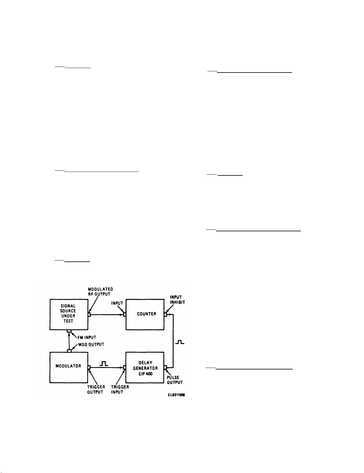
Pulse Profile Measurements
The use of the rear-
measurements -
the counter is inhibited
An ECL high
ECL devices are
-1 V at the INPUT INHIBIT
The
When
The
ments of these characteristics are
easily made with the counter and a
delaying pulse generator (see fig. 2-3).
The SIGNAL THRESHOLD OUTPUT of the coun-
ter is used to trigger the pulse genera-
tor. The generator’s output pulse is used
as an enable input to the counter. As the
pulse delay is varied, the measurement
window can be “walked” through the pulse.
A plot of frequency versus delay gives
the frequency-versus-time profile of the
pulse directly as shown in fig. 2-4. The
width of the measurement window is deter-
mined by the width of the pulse genera-
tor output.
nanoseconds or less can be used, although
wider windows yield higher accuracy.
b. Measurement Technique. Measure-
Figure 2-3.
Measurement Test Setup
Measurement windows of 50
Pulse Profile
a. Purpose.
ments can determine the average fre-
quency of a pulse.
however,
necessary.
tron may exhibit substantial frequency
shift near the leading and trailing
edges of the pulse, or a pulsed Gunn
diode oscillator may exhibit frequency
shift during a pulse due to peak power
thermal effects.
2-10
additional information may be
Automatic pulse measure-
In some cases,
For example,
a pulse magne-
Figure 2-4.
Pulse Profile Measurement
Page 29
TM 11-6625-3031-14
2-10.
Varying Signals.
not pulses at all but simply continuous
signals whose frequency varies repetitively with time. One example is the
measurement of the response of a device
such as a voltage-controlled oscillator
(VCO).
tuning voltage will produce a response
curve of frequency versus time, allowing
measurement of various settling times
such as post-tuning drift.
sible application would be the measure-
ment of linearity and amplitude for
frequency-modulated radar altimeter
signals.
shows a test setup designed to make
measurements on time varying signals.
It is similar to the pulse profile test
setup, except that in this case, since
there is always a signal present, a
trigger must be obtained from the modulating source.
pulse generator which controls the
measurement.
2-11.
Measurements.
ment is that of a repetitive sequence of
pulses differing in frequency. In this
Dynamic Characteristics of Time
a.
Purpose.
A square wave applied to the
b. Measurement Technique.
Multiple Pulse Signal
a.
Purpose.
Figure 2-5.
Measurement Test Setup
Many complex signals are
Another pos-
Fig. 2-5
This will trigger the
Another type of measure-
Time Varying Signal
measurement window is the period during
which the gate is actually open to enable the counting of a signal.
gate width will typically be 30 nanoseconds narrower than the pulse applied
width of the gate is always an integral
number of clock periods (5 nanoseconds).
For applications where the measurement
window needs to be known to an accuracy
better than 20 nanoseconds, it is rec-
ommended that the GATE OUTPUT on the
rear panel be observed directly on a
high speed oscilloscope. The desired
gate width may then be set by varying
the INPUT INHIBIT pulse width.
accurate pulse representation, the
oscilloscope input should be terminated
in a 50 ohm load.
necessary to measure the signal frequency at a precise point in time, the
internal delays of the measuring instrument can be significant. The total
delay between the time a signal is
applied to the counter input connector,
and the time it is available to be
case, it is desirable to measure the
frequency of each pulse in the sequence
separately.
b. Measurement Technique. The same
test setup as shown in fig. 2-5 is
required, with the trigger pulse syn-
chronous with the sequence.
measurement,
simply to discriminate between pulses.
The enabling pulse can be slightly
wider than the pulse to be measured.
The counter will automatically restrict
the measurement window entirely within
the pulse.
the enabling pulse,
the sequence can be separately measured.
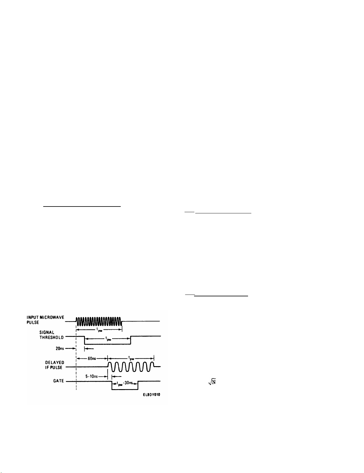
2-12.
internal timing within the counter is of
no concern to the user.
applications where a few nanoseconds are
significant,
operation are important.
two areas:
and internal timing delays.
b. Measurement Window Width. The
to the INPUT INHIBIT connector.
c.
Timing Considerations.
a.
General.
Internal Timing Delays.
the INPUT INHIBIT is used
By shifting the delay time of
each input pulse of
Under most circumstances,
some details of internal
measurement window width
In this
However, in
These involve
This
The
For
When it is
2-11
Page 30
TM 11-6625-3031-14
counted,
The SIGNAL THRESHOLD OUTPUT on the rear
panel typically occurs 20 nanoseconds
after the signal is applied.
OUTPUT at the rear panel occurs at the
measurement time with virtually no
delay.
time positioning of a signal is required,
it is necessary to consider that the
GATE OUTPUT signal,
measurement period, is actually making
a measurement of the signal which
appeared at the input connector 60 nano-
seconds earlier. If the SIGNAL THRESHOLD OUTPUT is used as an indication of
input signal, then it occurs 40 nano-
seconds prior to measurement.
shows the relative timing of these signals for a pulsed input signal.
however, is not a function of input signal characteristics.
2-13.
a. General Considerations.
—
measurement accuracy is generally speci-
fied as time base accuracy ±1 count.
This means that the frequency measurement is in error by the same percentage
as the time base reference oscillator.
The maximum error in the time base is
the sum of various possible errors,
such as aging rate, temperature, etc.
count, is derived from the relative
timing of gate and signal.
stated, if an event occurs every 400
milliseconds,
Figure 2-6.
is nominally 60 nanoseconds.
The GATE
In other words, when absolute
which represents the
Fig. 2-6
Timing,
Accuracy.
(1) In a cw frequency counter,
(2) The second type of error, ±1
Simply
a counter could measure
Internal Timing Delays
either 2 or 3 events in a one second
interval,
signal and the gate are asynchronous.
error in a cw counter is gate error.
A gate is supposed to represent a precise number of reference oscillator
cycles.
in the rise and fall times of various
circuits,
be a fixed amount wider or narrower
than desired. If this error is less
than one period of the maximum input
frequency, no counter error will occur.
Thus a 300 MHz counter needs a gate
accurate to about 3 nanoseconds.
error can contribute to the overall
error In pulse frequency measurements.
In fact for narrow pulses, the second
and third sources of error, which are
usually ignored in a cw counter, become
the dominate sources of error in a
pulse counter.
error in the time base reference oscillator results in a proportional frequency measurement error.
sources of time base error are aging
rate and temperature. The temperature
compensated crystal oscillator (TCXO)
reduces temperature instability to less
than 2 x 10⁻⁶.
frequency standard, this error can be
made less than one count, and thus
becomes insignificant.
obtain high resolution, the frequency
of a number of measurements is averaged.
Each individual measurement has a ±1
count uncertainty as previously noted.
If N measurements are made, then an
uncertainty of ±N counts is possible,
but very unlikely.
averaged measurement will follow the
rules of statistics, in that succes-
sive measurements will vary randomly
to a certain degree.
of the readings (63 percent) will fall
between ± counts; this is called
the rms averaging error.
number of gates required to accumulate
100 microseconds or 1 millisecond of
gate time.
since the processed input
(3) A third possible source of
Due primarily to differences
the actual gate will usually
(4) Each of these three sources of
b.
Time Base Errors. A frequency
Two main
By calibration against a
c.
Averaging Error. In order to
The resultant
In fact, most
N is the
The gate is typically
2-12
Page 31

TM 11-6625-3031-14
30 nanoseconds
pulse, so that
narrower than the input
determined and corrected. As an
example, the measured time base output
is 10.0001 MHz.
1 x 10
readings will be 1 x 10
quency.
where PW =
F
= 200 kHz with 100 µsec gate,
pulse width in microseconds
Band A; or 60 kHz with
be 10 kHz low.
can be corrected for this error, the
counter should be recalibrated as soon
as possible.
1 msec gate, Band A; or
100 kHz with 100 µsec gate,
Band B; or 30 kHz with
1 msec gate, Band B.
quency and pulse width can be virtually
eliminated.
simulating a pulse input and determining
d.
Gate Error.
(1) When narrow pulses are counted,
the gate is opened many times in order
to obtain a high resolution measurement.
the gate error.
can then be added to, or subtracted
from,
obtain the correct frequency.
Each time the gate opens and closes,
there will be a small but finite error.
The total error is proportional to the
number of times the gate is cycled during a measurement, and is thus inversely
proportional to the gate width.
This
error is also related to both temperature and input frequency.
case error,
including all variables, is
The worst
specified for the counter as:
error using a cw source at approxi-
mately the same frequency (within
25 MHz) as the indicated measurement.
A pulsed input is then simulated by
applying an enable signal, of the same
width as the pulse to be measured, to
the INPUT INHIBIT connector.
error is the difference in reading
between the pulsed and non-pulsed
measurement of the same cw signal.
This procedure provides the true gate
error,
any possible pulling of the signal
source.
-6
high in frequency, and all
The time base is thus
-6
low in fre-
Thus, a reading at 10 GHz will
Although the reading
b. Gate Error.
—
(1) Gate error at any given fre-
This is accomplished by
This calibration factor
the indicated measurement to
(2) First, determine the gate
Gate
and avoids error associated with
where PW =
pulse width in microseconds.
(2) Unlike averaging error, which
is random, gate error is systematic,
and is not reduced by frequency
averaging.
2-14.
Techniques for Improving
Accuracy.
a. Time Base Calibration. A frequency
error in the time base oscillator results in the same percentage error in
the frequency reading for either cw or
pulsed signals.
By directly measuring
the 10 MHz time base frequency at the
10 MHz OUTPUT connector with a standard
of known accuracy, this error can be
2-15.
Operation Using General Purpose
Interface Bus.
a. General.
—
(1) The counter may be operated via
the General Purpose Interface Bus (GPIB)
and may be controlled by, listened to
and talked to by any device or devices
compatible with IEEE STD-488.
Table 2-4
lists the Capability Identification
Codes assigned to the counter.
This
code is also printed on the counter rear
panel adjacent to the GPIB 24-pin connector so that programming instructions
or keyboarding of a controller can be
interfaced with the counter configuration and capabilities.
(2) The IEEE STD-488 GPIB system
(fig. 2-7) consists of 16 signal lines
2-13
Page 32

2-14
Table 2-4.
TM 11-6625-3031-14
Page 33

TM 11-6625-3031-14
used to carry data, control, and
management information.
The 16 lines
are organized into three sets, as
follows:
(a) Data Bus (b)
Control -
3 signal lines
(c)
Management-
Data Byte Transfer
General Interface
5 signal lines.
8 signal lines
(3) The counter is a type B device
able to talk and listen (T1 and L4
codes). Mnemonics assigned to the vari-
ous signal lines are as follows:
(a)
Data Bus lines are:
DIO 1 through DIO 8 (Data Input/Output
line 1 through 8)
- used to transmit
message bytes in bit-parallel, byte-
serial format,
asynchronously and
usually in a hi-directional manner.
(b)
Data Byte Transfer Control
lines are:
DAV (Data Valid) - used to indicate the
condition (availability and validity) of
information on DIO signal lines.
Figure 2-7.
and Structure
GPIB Capabilities
NFRD (Not Ready For Data) - used to indicate the condition of readiness of
device(s) to accept data.
NDAC (Not Data Accepted) - used to indi-
cate the condition of acceptance of data
by device(s).
(c) General Interface Manage-
ment lines are:
ATN (Attention)
- used by a controller
to specify how data on the DIO signal
lines are to be interpreted and which
devices must respond to the data.
IFC (Interface Clear) - used by a controller to place the interface system,
portions of which are contained in all
interconnected devices, in a known
quiescent state.
SRQ (Service Request) - used by a device
to indicate the need for attention and
to request an interruption of the cur-
rent sequence of events.
REN (Remote Enable) - used by a con-
troller (in conjunction with other mes-
sages) to select between two alternate
sources of device programming data.
2-15
Page 34

TM 11-6625-3031-14
EOI (End Or Identify) - used by a talker
to indicate the end of a multiple byte
transfer sequence or, in conjunction
with ATN (by a controller), to execute a
polling sequence.
NOTE
The EOI function is not included
in this counter.
(4) The 16 GPIB lines are connected
to the rear-panel GPIB IEEE STD 488/
1975 connector as shown in table 2-5.
To the left of and below the connector
are seven ADDRESS SWITCHes for setting
the GPIB modes or addresses of the
counter.
b. On Line and Off Line Operation.
(1) The Talk Only On Line and Off
Line operation are summarized in table
2-6.
determines the mode of operation of the
counter. When the switch is set to the
1 position before power is applied to
the counter,
The setting of ADDRESS SWITCH 7
the counter can be a talker
Table 2-5. GPIB IEEE STD 488/1975
Connector Pin Assignments
Pin
10
11
12
Signal
1
DIO 1
2
DIO 2
DIO 3
3
DIO 4
4
EOI
5
(not used)
DAV
6
NRFD
7
NDAC
8
IFC
9
SRQ
ATN
(Shield)
line
Pin
13
14
15
16
17
18
19
20
21
22
23
24
Signal
line
DIO 5
DIO 6
DIO 7
DIO 8
REN
Gnd (6)*
Gnd (7)*
Gnd (8)*
Gnd (9)*
Gnd (10)*
Gnd (11)*
Gnd (Logic)*
only with continuous output from the
GPIB connector.
rate control (either by the front-panel
SAMPLE RATE control or Fast Active) and
output format (either ExponentScientific or Exponent-Four) is set by
ADDRESS SWITCHes 1 and 2.
other ADDRESS SWITCHes, 3 through 6, do
not effect the output when the counter
is being used in the Talk Only mode.
selected, ADDRESS SWITCH 7 is placed in
the 1 position before power is applied
to the counter. After power is applied,
the front-panel controls will be operative unless ADDRESS SWITCH 1 is in the
1 position,
RATE control will be inactive.
selected, ADDRESS SWITCH 7 is placed in
the 0 position before power is applied
to the counter.
the counter is accomplished by placing
ADDRESS SWITCHes 1 through 5 in the
appropriate configuration shown in
table 2-6.
counter will respond to the ASCII Listen
or Talk Address character that has been
set by the ADDRESS SWITCHes 1 through 5,
as indicated in table 2-7. Configura-
tion of the ADDRESS SWITCHes is shown in
fig. 2-8.
Selection of sample
The four
(2) When Off Line operation is
in which case the SAMPLE
(3) When On Line operation is
Address assignment to
After being turned on, the
NOTE
ASCII ? and is reserved for
GPIB Unlisten and Untalk and
therefore cannot be assigned as
an address to a counter or any
other device.
settings of 1 1 1 1 0 cannot be
used as an address for the
counter.
ADDRESS SWITCH
*Gnd ( ) refers to the signal ground
return of the referenced contact pin;
EOI and REN (5, 17) ground return on
pin 24.
2-16
Figure 2-8. GPIB IEEE STD 488/1975
ADDRESS SWITCH Positions
Page 35

TM 11-6625-3031-14
Mode
On Line
Operation
Off Line
Operation
Table 2-6.
ADDRESS SWITCH
1
2
A1
A2 A3 A4
0* 0*
1*
0*
0*
1*
1*
1*
On Line and Off Line ADDRESS SWITCH Settings
Function
5
4
3
x x x
x x x
x x x
x x x x
A5
6
7
Address assignment to counter.
ADDRESS SWITCH 7 must be in 0
0
x
position.
Continuous output determined by
1
x
x
x
SAMPLE RATE control. Exponent in
scientific format.
Continuous output, fast active.
SAMPLE RATE control inactive.
1
Exponent in scientific format.
Continuous output determined by
SAMPLE RATE control.
1
four output format.
Continuous output, fast active.
SAMPLE RATE control inactive.
1
Exponent-four output format.
Exponent-
x* x*
Don’t care
x =
*
= May be continuously set or reset as long as ADDRESS SWITCH 7 is set to 1 during
power application. After application of power,
to 0.
c. Remote/Local Operation.
(1) In addition to On Line and Off
Line modes of operation, the GPIB provides for Remote and Local Operation.
In Remote Operation, the counter is On
Line and is under control of programming
signals from a controller. In Local
Operation, the counter front-panel controls are active and controller signals
do not affect counter operation; how-
ever,
the GPIB (Talker Only Mode) depending
on the counter rear-panel ADDRESS
SWITCH settings.
switch between Remote and Local by
sending the appropriate ASCII codes for
Remote Enable (REN) or Go To Local control (GTL) to the counter.
in Remote and the controller has
output signals are available to
The controller can
(2) When the counter is On Line and
x x x
0
x
No output
ADDRESS SWITCH 7 may be set
selected the counter with ATN (Atten-
tion) to the counter address followed
by Listen,
programming instructions from the con-
troller.
select all control functions of the
counter front panel except power on/off,
sample rate,
instructions from the controller to the
counter are identified as Device Depend-
ent Data.
d. Device Independent Data, On Line
Operation.
consists of the following, which are
sent by controller while in the command
mode.
(1) GO TO Local (GTL). An
addressed command given by the con-
troller.
its Listen address prior to the GTL
the counter will respond to
Programming instructions can
and self-test. Programming
Device independent data
The counter must have received
2-17
Page 36

TM 11-6625-3031-14
ADDRESS SWITCH
1
0
1
0
1
0
1
0
1
0
1
0
1
0 0
1
2 3 4
Setting
0 0 0
0 0
1
1
0
0
1 1
1
0
0 0
1
1
0
Table 2-7.
0
0 0
0
1
1
1
0
0
0
1 1
1 1 1
0
0
0
0
0
1
1
1
1
ADDRESS SWITCH Settings vs ASCII Characters
ASCII
5
1
1
1
1
1
1
1
1
1
1
1
1
1
Listen address Talk address Talk/Listen
character character address
SP
!
"
#
$
%
&
'
(
)
*
+
,
ASCII *Decimal
@
A
B
C
D 04
E
F 06
G
H 08
I
J
K
L
M
00
01
02
03
05
07
09
10
11
12
13
0
1 1
0
1
0
1
0 0
1
0
1 1
0 0
1
0
1
0
1
0
*Decimal Talk/Listen addresses are provided as a cross-reference for controllers
which use them in their program instructions.
1
0
0
1
1
0
1
0
1
1
0
0
1
1
1
0
0
0
0
1
1
1
1
0
0
0
0
1
1 1
1
1
1
0 0
0
0 0
0 0 3
0 0
0 0
0
0
1
1
1
1
1
1
1
1
0
0
0
0
0
0
0
0
0
0
:
,
.
/
0
1
2
4
5
6
7
8
9
<
=
>
N
O
P
Q
R
S
T
U
V
W
X
Y
Z
[
\
]
14
15
16
17
18
19
20
21
22
23
24
25
26
27
28
29
30
2-18
Page 37

TM 11-6625-3031-14
command being issued.
received,
the counter will go to the
Local mode with all front-panel
switches operative.
When GTL is
Fast Cycle, or the
one alpha and one numeric, characters,
depending on the function being
programmed.
last YIG Preset command received by the
counter while in the Remote mode, will
remain and will not be cleared by this
command.
The front-panel REMOTE indi-
of the value portion of the function
being programmed.
optional.)
cator will be off.
(2) Selected Device Clear (SDC).
An addressed command given by the con-
troller.
The counter must have received
numeric value assigned to the function
being programmed.
zeros need not be programmed.
its Listen address prior to the SDC
command being issued.
received, the counter will be cleared
to its initial state and remains
When SDC is
symbol used with the value portion of
the function being programmed M = mega-
hertz (106), G =
addressed to Talk or Listen. ADDRESS
SWITCHes 1 - 7 will be read.
(3) Device Clear (DCL). Same as
SDC command, except that counter’s
Listen address does not have to be
received prior to issuing of DCL.
(4) Serial Poll Enable (SPE). An
addressed command given by the
controller.
(5) Serial Poll Disable (SPD). An
addressed command which negates SPE.
Device Dependent Data, On Line
e.
Operation.
(1) Definition.
data is that data,
Device dependent
inputted in string
form, to which the counter uniquely
responds while in the Remote mode, and
while addressed to Listen.
(2) Implementation. While in the
command mode,
the controller places the
counter in the Remote mode by setting
the REN line active, then by sending the
listen address of the counter.
When the
command will program a YIG Preset equal
to the Value and Scale Factor. Nega-
tive YIG Presets will be taken as
positive.
al), Value and Scale Factor.
Example:
counter is in the Remote mode and addressed to Listen, the controller
leaves the command mode and enters the
data transfer mode.
It is in this
mode and counter setup that device
dependent data can be sent by the programmer.
The mnemonics, format, and
specifications for the device dependent data are described below and sum-
Example:
Between YP and M or G, only the Sign,
numeric Value, or decimal point will be
recognized by the counter.
information will be updated only during
a converter reset.
marized in table 2-8.
(3) Format.
The format for device
dependent data from a controller is as
follows:
Mnemonic
Sign
Value Scale Factor
(a) Mnemonic. Two alpha, or
(b) Sign. The sign “+” or “-”
(The “+” sign is
(c) Value.
The particular
Leading and trailing
(d) Scale Factor. Exponent
9
gigahertz (10
).
NOTE
If any of the above does not per-
tain to the particular function
being programmed, it should be
omitted.
For example, BA:
Mnemonic.
The Sign, Value, and
BA is the
Scale Factor are not necessary.
This function sets the counter to
Band A.
(4) Mnemonics.
(a) YIG Preset (YP). This
Mnemonic YP, Sign + (option-
YP 1.2 G or YP - 1.2 G.
Both
program 1.2 x 10⁹ Hz (1.2 GHz)
into the counter.
YP M or YP G:
Clears the YIG
Preset.
YIG preset
NOTE
In the following commands, the
Mnemonic is shown following the
command title. Sign, Value, and
Scale Factor are not used.
2-19
Page 38

TM 11-6625-3031-14
Table 2-8. Programming Summary
Function Value
YIG Preset
Cycle
Counter
Reset
Counter and
Converter
Converter
Auto
Converter
Manual
Hold Active
Hold Passive
1 ms Gate
Time Active
1 ms Gate
Time Passive
Band A
ASCII
Mnemonic
YP
CC
RC
CA
CM
HA No data
HP
TA Gate time:
TP
BA
Sign
+
range
Scale
Factor
M or GYIG preset
Comments
+ sign optional
One-shot action
One-shot action
transmission
1 ms
Gate time:
100 µs
Band B
Remote
Resolution:
10 kHz
Remote
Resolution:
100 kHz
Remote
Resolution:
1 MHz
Fast Active
Fast Passive
Transmit
Normal
Transmit
Service
Request
ExponentScientific
ExponentFour
BB
R4
R5
R6
FA
FP
TN
TS
ES
E4
Sample rate
Sample rate
Output data
Output data
2-20
Page 39

TM 11-6625-3031-14
Function
Device Clear
(DCL)
Selected
Device Clear
(SDC)
Go to Local
Control
(GTL)
Serial Poll
Enable (SPE)
Serial Poll
Disable
(SPD)
My Listen
Address
(MLA)
My Talk
Address
(MTA)
Table 2-8.
ASCII
DC4
EOT
SOH
CAN
EM
Mnemonic
Programming Summary - Continued
Sign Value
Scale
Factor
Controller
dependent
Controller
dependent
Controller
dependent
Controller
dependent
Controller
dependent
Device dependent
Device dependent
Comments
Unlisten Controller
dependent
Untalk Controller
(b) Cycle Counter (CC). This
command resets the basic counter section,
ing.
reset occurs; to obtain another reset,
CC must be resent.
(RC).
basic counter and converter sections,
and causes the counter to take a new
reading.
occurs;toobtain another
must be sent again.
HA is sent in the Remote mode, the
counter stops taking readings, data
transmission is stopped, and the last
frequency read is displayed and held by
the counter.
(subparagraph (s)
will have no effect upon the counter’s
and causes it to take a new read-
When the CC command is sent,
(c)
This command resets both the
When RC is sent, a reset
(d) Hold Active (HA). When
—
Reset Counter and Converter
reset, RC
In the Fast Active mode
below), the HA command
dependent
display operation while in the Local
mode, but will stop data transmission.
If programmed during the FA mode, and FA
is then terminated, the counter will
respond to the HA command.
(e) Hold Passive (HP). This
command terminates HA.
1 ms Gate Time Active (TA).
(f)
This command puts the counter in the
1 ms gate time mode.
1 ms Gate Time passive
(g)
(TP).
selects Band
to 950 MHz.
selects Band
to 18 GHz.
command selects the automatic sweep
mode of the counter, and operates in
This command terminates TA.
(h)
Band A (BA).
A of the counter, 300 MHz
(i)
Band B (BB).
B of the counter, 925 MHz
Converter Auto (CA). This
(j)
This command
This command
2-21
Page 40

TM 11-6625-3031-14
conjunction with the YIG Preset (YP)
command and value,
(k)
Converter Manual (CM).
This command selects the Manual mode
of the counter, and operates in conjunc-
tion with YIG Preset (YP) command and
value.
(m) Transmit Normal (TN). This
command causes the counter to continuously transmit its reading when addressed to Talk.
(n)
Transmit Service Request
(TS).
This command causes the counter
to take a reading, format the data,
store the result, and activate the SRQ
line to indicate to the controller that
a reading is ready for transmission.
After the reading is transmitted, the
SRQ line is deactivated and the process
is repeated.
The status byte trans-
mitted during serial polling indicates
that data is ready for transmission
(bit 7 active).
NOTE
f. Output Data Format.
—
(1) Basic Format.
(a) The output data is trans-
mitted with the most significant byte
first,
form, and in 7-bit ASCII code.
in a bit-parallel, byte-serial
The
general format is
XX.XXX xx Ey CR LF
where CR is Carriage Return, LF is
Line Feed,
x represents digits 1 through
9, and y the exponent 0, 3, 6, or 9.
The decimal point will be located in
the proper place, though it may be
deleted depending on the data output
format and/or the reading.
(b)
There will always be
12 bytes of information transmitted per
reading.
Leading zeros are always replaced with ASCII code Null characters.
The last four bytes transmitted are
always
Remote Resolution commands determine the resolution of the
counter readings while in the
Remote mode.
where y represents exponents 0, 3, 6, or
9, and CR and LF the ASCII codes used
as delineators.
(p) Remote Resolution: 10 kHz
(R4).
(R5).
(R6).
Resolution of 10 kHz.
(q) Remote Resolution: 100 kHz
Resolution of 100 kHz.
(r) Remote Resolution: 1 MHz
Resolution of 1 MHz.
(s) Fast Active (FA). The FA
is used to—specify the exponent 0, 3,
6, or 9, depending upon the value and
format of the reading.
output commands (E4 or ES) affect only
the numeric portion and exponent value
of the transmitted data.
command causes the counter to go into
the fast cycle mode of operation. In
Format.
this mode, the front-panel SAMPLE RATE
control is inactive, and the fastest
sample rate transmissions are attained.
(t) Fast Passive (FP). This
command terminates FA.
(u)
Exponent-Scientific (ES).
This command causes the counter to out-
put data in an engineering notation
format if counter is addressed to Talk.
(v) Exponent-Four (E4). This
command causes the counter to provide
exponent value of the transmitted data
will always be 4 with no decimal point
inserted.
mitted as seen on the counter’s frontpanel display, with the resolution of
the reading dependent upon the frontpanel switches or the remote resolution
commands.
resolution setting are set to zero.
Some examples in the E4 format are as
data in four exponent format if counter
is addressed to Talk.
Null character.
Ey
CR LF
(c)
The ASCII code character E
Thus the data
(2) Exponent-Four Output (E4)
(a) In the E4 format, the
The reading will be trans-
The digits affected by the
follows, with N representing an ASCII
Page 41

(b)
Display reading:
11 234.56 MHz
Resolution
10 kHz
100 kHz
1 MHz
(c) Display reading:
434.56 MHz
Resolution
10 kHz
100 kHz
1 MHz
Reading transmitted
N1123456 E4 CR LF
N1123450 E4 CR LF
N1123400 E4 CR LF
Reading
NNN43456 E4 CR LF
NNN43450 E4 CR LF
NNN43400 E4 CR LF
transmitted
TM 11-6625-3031-14
switches on the counter front panel),
those digits affected by the resolution
are replaced by zeros.
ES format are:
Frequency input:
1.
1 234.56 MHz
Remote
resolution
10 kHz
100 kHz
1 MHz
.56 GHz
Reading transmitted
N 1.23456 E9 CR LF
NN 1.2345 E9 CR LF
NNN 1.234 E9 CR LF
2. Frequency input:
Examples in the
(3) Exponent-Scientific Output (ES)
Format.
(a) In the ES format, the
exponent value of the transmitted data
is always 0,
the frequency reading.
is entered to correspond to the exponent
so the transmitted data will be a mixed
number of whole and fractional parts,
such as 545.727, 15.72, 5.2, etc.
transmitted as ASCII Null characters,
and the digits which are affected by the
remote resolution are disregarded.
(Null characters are inserted at the
beginning of the data so that 12 charac-
ters are always transmitted.)
quency reading includes a decimal point
that is not necessary, the decimal point
is disregarded and a Null character is
inserted at the beginning of the data.
the whole part of the number being
transmitted (no decimal point or fractional part), zeros are inserted for
those numbers before being transmitted.
the entire—number,
transmitted with the exponent value of
the reading,
exponent value the manner in which the
resolution covered the reading.
example:
NNNNNNNOEO CR LF.
used (by pressing the RESOLUTION
3, 6, or 9, depending on
A decimal point
(b)
All leading zeros are
(c)
If the resolution or fre-
(d)
If the resolution affects
(e)
If the resolution covers
then all Nulls are
so the user can tell by the
For
0 Hz is transmitted as
(f) When local resolution is
printed out on a printer, are shown
below.
conditions of the counter
Line mode, after power is
commands SDC or DCL have been issued by
the controller, are as follows:
are in tri-state mode.
(REMOTE indicator not lighted).
SWITCHes 1 through 7.
Talk or Listen
Remote
resolution
10 kHz
1 MHz
(g) Transmitted readings, as
Leading Null characters are not
printed.
Printer output
434.6E6 434 600 000 Hz
11.7693E9
539.99999E9
OEO 0 Hz
g. Wake-up Conditions.
(1) Signal lines of the data bus
(2) Counter is in Local mode
(3) Counter has sampled ADDRESS
(4) Counter is not addressed to
(5) No YIG Preset (YP).
Reading
NN 560.00 E6 CR LF
NNNNN 560 E6 CR LF
NOTE
539 999 990 Hz
E6
? but
transmitted
Frequency
11 769 300 000 Hz
in MHz range
The wake-up
for the On
applied or
2-23
Page 42

TM 11-6625-3031-14
(6) Transmit
(7) Remote (8) Remote (9) Remote -
Passive (TP).
(10) Remote -
(R4).
(11) Remote (12) Remote -
(ES) format.
(13) Remote (14) Counter and converter have been
reset.
h. Band A (300 -
Peak power applied to BAND A
input connector should be between
-10 and +10 dBm for normal operation.
+27 dBm or damage to the counter
may result,
is turned off.
(1) Perform the preliminary pro-
cedures of paragraph 2-7 b.
(2) Press the POWER switch to turn
off the counter.
(3) Select an address for the
counter by setting the GPIB IEEE STD
488/1975 ADDRESS SWITCHes 1 through 5
(fig. 2-8) in accordance with table 2-7.
Make sure that ADDRESS SWITCH 7 is set
to 0.
(4) Connect the GPIB controller to
counter with a GPIB cable and appropriate interface to the counter rear-panel
GPIB IEEE STD 488/1975 connector.
(5) Press the POWER switch to turn
on the counter.
(6) Apply power to the controller.
(7) Connect the signal source to
the BAND A input connector.
(8) Program REN (Remote Enable)
from the controller.
(9) Check that the counter front-
panel REMOTE indicator lights.
(10) Program BA to select Band A.
Execute.
(11) Select and program R4, R5, or
R6 for the desired resolution.
(12) If the input signal level is
high enough for counting, both the
Peak input must not exceed
Normal (TN).
Band B (BB).
Hold Passive (HP).
1 ms Gate Time
Resolution:
Fast Passive (FP).
Exponent-Scientific
Converter Auto (CA).
950 MHz) Operation.
CAUTION
even if the counter
10 kHz
Execute.
front-panel LEVEL and LOCK indicators
will light.
control to provide the desired display
update rate. The GATE indicator will
flash in accordance with the sample rate.
If the control is set to its switched
HOLD position,
the last reading. If a new reading is
desired, program CC to cycle counter.
Execute.
location,
the counter SAMPLE RATE control to
obtain a HOLD, retaining the last read-
ing,
Execute.
switching the counter SAMPLE RATE control out of HOLD), program HP (Hold
Passive) to terminate the Hold Active.
Execute.
trol with ASCII SOH or with a
controller-unique command as appropriate.
have the REMOTE indicator off and
should be in the Local operation Off
Line modes.
Operation.
procedures of paragraph 2-7 b.
paragraph 2-15 h,
(9), except that in step (7) connect
the signal source to the BAND B input
connector.
(13) Turn the counter SAMPLE RATE
the display will retain
(14) If the counter is in a remote
the controller can override
To program a HOLD:
(a)
Program HA (Hold Active).
(b) To remove the HA (same as
(15) Program GTL (Go To Local) con-
Execute.
i. Band B (925 MHz - 18 GHz)
Peak power applied to the BAND B
Input connector should be within
the following ranges for normal
operation:
925 MHz - 10 GHz: -10 to +10 dBm
10 - 18 GHz:
The peak input power must not
exceed +30 dBm or damage to the
counter may result, even if the
counter is turned off.
(1) Initial Procedures.
(a)
(b) Perform procedures of
The counter should now
.
CAUTION
-5 to +10 dBm
Perform the preliminary
steps (2) through
2-24
Page 43

(c)
Program BB to select
Band B.
Execute.
(d) Select and program R4, R5,
or R6 for the desired resolution.
Execute.
(e) If the input signal level
is high enough for counting, both the
front-panel LEVEL and LOCK indicators
will light.
If the REDUCE SIGNAL indi-
cator lights, the input signal power is
approaching the maximum safe operating
level and should be reduced.
(2) Automatic Mode. In the auto-
matic mode, the counter searches for the
input signal by sweeping from a start
frequency which is 105 MHz above a pre-
set frequency.
(a)
Program CA (Converter
Auto).
Execute.
NOTE
For full search, YP (YIG Preset)
is not programmed, which is
equivalent of setting the START
SWEEP thumbwheel switches to
00.0 GHz.
(b) To improve acquisition
speed, the sweep start frequency may be
set by programming YP (YIG Preset) followed by a number. The lowest frequency
which can then be acquired and displayed
or recorded will be 105 MHz above the
YIG Preset; erroneous readings may be
displayed or recorded if the applied
signal frequency is less than 105 MHz
above the YIG Preset.
(c)
To set the sweep start
frequency equivalency of thumbwheel
settings, program YP followed by a value
and scale factor.
Example:
for a start
frequency of 1.2 GHz, program YP 1.2 G
(mnemonic YP,
G).
Execute.
value 1.2, scale factor
(d) To reset the YIG Preset
frequency to 00.0 GHz, program YP G
(leaving out the value). Execute.
NOTE
To change the YIG Preset fre-
quency from one value to another,
or before resending the same
TM 11-6625-3031-14
value, YP must be set back to
00.0 GHz and the preset frequency
programmed.
(e)
Adjust the SAMPLE RATE
control or program as described in
paragraph 2-15 h, steps (13) through
(15).
(3) Manual Mode. In the manual
mode,
reducing the acquisition time.
the search sweep is inhibited,
However,
the signal frequency to be measured must
be between 105 and 325 MHz above the
preset frequency.
(a)
Program CM (Converter
Manual).
Execute.
(b)
Program YIG Preset, Value,
and Scale Factor to the desired frequency which must be 105 MHz to 325 MH
lower than the signal frequency.
ple:
if the expected measurement
Z
Exam-
frequency is 12.35 GHz, program
YP 12.2 G (which places the input frequency 105 to 325 MHz above the preset
frequency).
Execute.
NOTE
Erroneous readings may be displayed or recorded if the
applied signal frequency is out-
side of the preset range.
(c)
Adjust the SAMPLE RATE
control or program as described in
paragraph 2-15 h, steps (13) through
(15).
j. Programming Example Using Calcu-
lator as Controller.
(1) A typical program, utilizing a
Hewlett-Packard 9815 Calculator as a
GPIB controller, is shown in table 2-9.
The program sets the counter as follows:
(a)
Band A (BA)
(b)
Remote Resolution - 10 kHz
(R4)
(c) 1 ms Gate Passive (TP)
(d)
Hold Passive (HP)
(e)
Fast Active (FA)
(f)
Exponent-Scientific (ES)
(g)
No YIG Preset (YPM)
(2) The program then instructs the
counter to take frequency readings and
2-25
Page 44

TM 11-6625-3031-14
Table 2-9.
Program step
0000
0001
0003
0004
0005 END Clear COMMAND mode
0006 CMD 5 Enter COMMAND mode
0008
0009
0010
0011
0012
Typical Program Using Hewlett-Packard 9815
Calculator as Controller
Command
Clear
CMD 5
@
B
U
3
Blank
B
Clear counter
Controller to COMMAND mode
Set REN line active
Controller talk address
Counter listen address
Counter goes to data transfer mode
Device dependent data starts here
Comment
0013
0014
0015
0016
0017
0018
0019
0020
0021
0022
0023
0024
0025
A
R
4
T
P
H
P
F
A
E
S
Y
P
Counter set to Band A
Resolution 4
1 ms Gate Passive
Hold Passive
Fast Active
Exponent-Scientific
Clear YIG Preset
2-26
0026
M
Page 45

TM 11-6625-3031-14
Table 2-9.
Typical Program Using Hewlett-Packard 9815
Calculator as Controller - Continued
Program step Command
0027 END
0028 Clear
0029
1
0030 Enter
0031
0032
0033
0034
0035
1
9
Read 5 Read frequency
Print
Go to 0028 Repeat
0036 END
Comment
End device dependent mode
prints out the results.
frequency of 580.75 MHz, the print-out
might appear as
For an input
An example of such an output, in which
the program sampled the frequency at
different resolutions and printed the
results, is
580750000
580760000
580740000
580760000
580760000
580750000
(3) The character E and exponent
values are not presented; however, this
is entirely dependent on the controller.
Although the information was sent, the
controller formatted and printed the
data in this form.
The way in which
output data may be interpreted, and
how data is sent to the counter, is
entirely dependent on the controller
used.
(4) Programs may be written to
display the entire data transmission.
RESOLUTION SCAN
. . . . . . . . . . . . . . .
285.24E6
285.1E6
285E6
285.2E6
. . . . . . . . . . .
OFFSET SHIFT
. . . . . . . . . . .
OEO
900E3
9.9E6
99.9E6
999.9E6
9.9999E9
2-27/(2-28 blank)
Page 46

Page 47

TM 11-6625-3031-14
CHAPTER 3
OPERATOR AND ORGANIZATIONAL MAINTENANCE
Section I. LUBRICATION
3-1.
Section II. TROUBLESHOOTING PROCEDURES
3-2.
malfunctions which you may find during
operation or maintenance of the
counter.
inspections and corrective actions in
the order listed.
Table 3-1 lists the common
You should perform the tests/
Table 3-1.
MALFUNCTION
TEST OR INSPECTION
1. No display
Step 1. Check if rear-panel fuse is blown.
- power not supplied to instrument.
No lubrication is required for the counter.
Operator and Organizational Troubleshooting
CORRECTIVE ACTION
Replace fuse with fuse of proper rating for operating voltage:
1.5 A slow-blow for 115 Vac,
3-3.
malfunctions that may occur, nor all
tests or inspections and corrective
actions.
or is not corrected by listed corrective
actions,
This manual cannot list all
If a malfunction is not listed
notify your supervisor.
or 0.75 A slow-blow for 230 Vac.
Step 2. Check that power cable is seated in rear-panel mounted
connector.
Seat power cable connector.
Step 3. Check power cable for open circuit and/or damaged connector
blades.
Replace power cable.
2. SAMPLE RATE control has no effect on display.
Step 1. Check that rear-panel mounted STORAGE and MIN. PRF switches
are both in down position.
Set STORAGE switch to ON and MIN. PRF switch to 50 Hz.
Step 2. Check GPIB IEEE STD 488/1975 ADDRESS SWITCHes.
Set ADDRESS SWITCHes 1 and 2 to 0 position (top pushed in).
3-1
Page 48

TM 11-6625-3031-14
Table 3-1.
Operator and Organizational Troubleshooting - Continued
MALFUNCTION
TEST OR INSPECTION
CORRECTIVE ACTION
Step 3. Check that REMOTE indicator is not lighted.
If REMOTE indicator is lighted and GPIB controller is con-
nected,
Fast Active (FA) may be in control.
Program Fast
Passive (FP) and execute on GPIB controller to remove Fast
Active command. If programming and executing FP does not
correct,
Hold Active (HA) may be in control.
Program Hold
Passive (HP) and execute on GPIB controller to remove Hold
Active command.
3. RESOLUTION selector switches do not change display with signal source(s)
connected to input connector(s).
Step 1. Check that REMOTE indicator is not lighted.
If REMOTE indicator is lighted and GPIB controller is connected,
resolution commands R4,
R5, or R6 may be in control.
Program Go To Local Control (GTL) and execute.
4. Display shows incorrect or erratic reading for BAND A inputs.
Step 1. Check that LEVEL indicator is lighted.
CAUTION
Do not exceed +10 dBm peak power
input to the BAND A connector.
If not lighted,
increase signal level until LEVEL indicator
lights.
Step 2.
Press BAND A pushbutton firmly.
BAND A pushbuttons,
ending up with BAND A.
Cycle between BAND B and
Alternately selecting BAND A and BAND B pushbuttons may free
up contacts.
5. Display shows erroneous reading for BAND B inputs.
Step 1. Check PRESET FREQUENCY thumbwheel switch settings if in
MANUAL SELECT.
Setting must be 105 to 325 MHz below input
frequency.
Set thumbwheel switches to proper preset frequency.
Step 2. Check START FREQUENCY thumbwheel settings if in AUTO SWEEP mode.
Setting must be at least 105 MHz below input frequency.
3-2
Set thumbwheel switches to proper start frequency.
Page 49

TM 11-6625-3031-14
Table 3-1.
MALFUNCTION
TEST OR INSPECTION
6. Counter does not count correctly with GPIB controller connected.
Step 1.
Operator and Organizational Troubleshooting - Continued
CORRECTIVE ACTION
Check that rear-panel ADDRESS SWITCH 7 is set to 0
(top pushed in).
Set ADDRESS SWITCH 7 to 0.
troller power.
POWER pushbutton and apply power to GPIB controller.
should remove microprocessor lock-up so that GPIB controller
can function.
Wait five seconds,
Remove counter power and con-
then press counter
This
Section III. MAINTENANCE PROCEDURES
3-4.
tenance is limited to inspection,
exterior cleaning, fuse and power cable
replacement, and performance of the
counter self-test.
3-5.
Introduction.
Operator and organizational main-
Inspection.
housing does not come off. Firm
but careful rotation of the fuse
puller will lift up one end of
the fuse so that finger force
can remove the fuse.
heed this caution by exerting
too much force may damage the
plastic pivot of the built-in
fuse puller.
Failure to
Inspection is accomplished by performing the preventive maintenance
checks listed in table 2-3.
3-6.
paragraph 2-5.
3-7.
follows:
of counter and slide plastic fuse cover
over power connector.
Cleaning.
Cleaning instructions appear in
Replacement.
a. Fuse.
(1) Disconnect power cable at rear
The FUSE PULL lever attached
the body of the power module
Replace a blown fuse as
CAUTION
to
(2) Remove installed fuse by lift-
ing up on FUSE PULL lever.
(3) Visually inspect fuse, or
check with an ohmmeter, to confirm that
it is blown.
(4) Reinstall original fuse (if not
blown) or replace defective fuse with
one of proper rating:
for 115 Vat, 0.75 A slow-blow for
230 Vat.
(5) Slide fuse cover over fuse and
reconnect power cable to connector.
b.
Power Cable.
is frayed or damaged, it must be
replaced.
3-8.
counter must be tested in accordance
with the procedures in paragraph 2-7 b.
Test.
After each maintenance action, the
1.5 A slow-blow
If the power cable
3-3/(3-4 blank)
Page 50

Page 51

TM 11-6625-3031-14
CHAPTER 4
DIRECT SUPPORT AND GENERAL SUPPORT MAINTENANCE
Section I. REPAIR PARTS, SPECIAL TOOLS; TEST, MEASUREMENT, AND
DIAGNOSTIC EQUIPMENT (TMDE); AND SUPPORT EQUIPMENT
4-1.
equipment,
of Organization and Equipment (MTOE)
applicable to your unit.
4-2.
Equipment.
and support equipment are listed in the
Common Tools and
For authorized common tools and
refer to the Modified Table
Special Tools, TMDE, and Support
No special tools are required. TMDE
Equipment.
Section II. SERVICE UPON RECEIPT
4-4.
and prior
follow the assembly and preparation for
use instructions in paragraph 2-6. Be-
come familiar with the control settings
Upon receipt of the pulse counter
to performing maintenance
Section III. TROUBLESHOOTING
Maintenance Allocation Chart, Appendix B
of this manual.
4-3.
trated in the repair parts and special
tools list, TM 11-6625-3031-24P, cover-
ing direct support and general support
maintenance for this equipment.
and indicators by reviewing the operating
graph 2-7.
following troubleshooting instructions.
Repair Parts.
Repair parts are listed and illus-
instructions
Then proceed with the
starting
with para-
4-5.
vided so that you can match what is
observed on the counter with the symptom
index and, from there, go to the page
in the troubleshooting table which
covers the malfunction. Use of the
counter operating controls and display
observation constitutes the initial
troubleshooting, followed by measure-
ments of increasing complexity.
should start with the obvious, for
example:
connections, improper seating or poor
connection of cables, etc.
Introduction.
a. Table 4-1, a symptom index, is pro-
b. Standard troubleshooting practice
blown fuses,
power and signal
After these
basic troubleshooting practices have
eliminated the obvious, then disassembly
or cover removal of the counter should
be considered.
SAFETY PRECAUTION
A periodic review of safety pre-
cautions in TB 385-4, Safety Precautions for Maintenance of Electrical/Electronic Equipment, is
recommended.
is operated with covers removed,
DO NOT TOUCH exposed connections
or components.
are not grounded when making connections or adjusting components.
When the equipment
MAKE CERTAIN you
4-1
Page 52

TM 11-6625-3031-14
DO NOT SERVICE OR ADJUST ALONE
Do not attempt internal service
or adjustment unless another person, capable of performing first
aid, is present.
c.
The troubleshooting table lists the
common malfunctions which you may find
during the operation or maintenance of
the counter or its components.
should perform the tests/inspections
and corrective actions in the order
listed.
d. This manual cannot list all mal-
functions that may occur, nor all tests
or inspections and corrective actions.
You
Table 4-1.
Symptom
If a malfunction is not listed or is not
corrected by listed corrective actions,
notify your supervisor.
NOTE
General Purpose Interface Bus
(GPIB) troubleshooting procedures
are in the depot maintenance work
requirements,
3031, for this equipment.
4-6.
1-3,
locations are shown in fig. 4-1.
out schematic diagrams are located in
the rear of this manual.
Symptom Index
Reference Diagrams.
Block diagrams are shown in fig. 1-2,
and 1-4.
CECOM DMWR 11-6625-
Subassembly and cable
Fold-
Troubleshooting
procedure
page
1. Display
No zeros
Display
DISPLAY
Display
200 MHz
Missing
Band A incorrect reading
Band B incorrect reading
2. LED Indicators
LEVEL indicator does not light.
LEVEL indicator blinks or lights continuously
without Band B input signal
LOCK indicator does not light
LOCK indicator blinks or lights continuously
without Band B input signal
GATE indicator does not light
REDUCE SIGNAL indicator does not light
does not indicate 88 888.88 when TEST
pushbutton is pressed
does not indicate 200 MHz when TEST
pushbutton is pressed
digit
4-4
4-4
4-6
4-6
4-7
4-8
4-10
4-13
4-13
4-14
4-15
4-15
4-15
4-16
4-2
Page 53

TM 11-6625-3031-14
Figure
4-1.
Subassembly and Cable Locations
4-3
Page 54

TM 11-6625-3031-14
MALFUNCTION
TEST OR INSPECTION
1. No zeros.
Step 1.
Step 2.
Table 4-2.
Direct Support and General Support
Troubleshooting
CORRECTIVE ACTION
Check if rear-panel fuse F1 is blown.
Replace fuse with fuse of proper rating for line operating
voltage:
1.5 A slow-blow for 115 Vac, 0.75 A slow-blow for
230 Vat.
NOTE
While inspecting fuse or replacing fuse make
sure that appropriate line voltage is visible
on voltage selector card under fuse post
housing.
Card should be seated so that it
does not interfere with slide protective
cover.
Check that power cable is seated in rear-panel connector.
Step 3.
Step 4.
Step 5.
Seat power cable.
Inspect power cable for physical damage.
Remove cable from
counter and check continuity.
Replace power cable.
Check that following cables are seated properly at both ends:
W22 from transformer T1 to Power Supply A107.
W17 from Display A110 to Counter Interconnect A100.
W14 from Display A110 to Count Chain Control A102.
W46 from Count Chain A103 to GPIB BCD Output AM120.
W47 from Count Chain A103 to GPIB BCD Output AM120.
W1 from Count Chain A103 to High Frequency A106.
Seat cable connections.
Place rear-panel MIN.
switch in ON position.
button.
If zeros now appear on display, Control A104 may be faulty.
PRF switch in 50 Hz position and STORAGE
Press and release front-panel RESET push-
Remove and replace Control A104.
4-4
Step 6.
Check cables W1, 46, and W47 for opens or shorts.
Replace defective cable.
Page 55

TM 11-6625-3031-14
MALFUNCTION
TEST OR INSPECTION
Step 7.
Step 8.
Table 4-2.
Direct Support and General Support
Troubleshooting - Continued
CORRECTIVE ACTION
Check continuity of cables:
W17 and W14 from Display A110.
If open or shorted, replace Display A110.
W22 from transformer T1.
If open or shorted,
replace transformer T1.
Disconnect cable W27 from J8 on Counter Interconnect A100
(fig. 4-2).
Measure dc voltages between ground and pins of J8,
which should be +5 V at pin 1, -5.2 V at pin 2, +12 V at pin 3,
and -12 V at pin 4.
If one or more voltages are not as specified, proceed to step 9.
If all voltages are normal, remove and replace the following
circuit cards in sequence specified:
Count Chain Control A102
Count Chain A103
Step 9.
Step 10.
Step 11.
Control A104
Gate Generator A105
High Frequency A106
Display A110
GPIB Remote/Local Control AM121
GPIB BCD Output AM120.
Same as step 8.
Disconnect all circuit cards and cables, one at a time, until
abnormal voltage(s) are restored to correct level.
Replace
defective circuit card or module which caused fault.
Disconnect cable W22 from A107J1. Check for ac voltages on
cable connector:
18 volts ac between pin 1 (brown wire) and
pin 2 (red wire), 9 volts ac between pin 4 (yellow wire) and
pin 5 (green wire).
If ac voltages are normal, Power Supply
A107 may be faulty.
Replace Power Supply A107.
Remove protective cover from power module (31, fig. 4-3) and
check for following ac voltages on power module:
pins F to D,
115 volts ac; pins E to C, 115 volts ac. If ac voltages are
normal,
transformer T1 may be faulty.
Replace transformer assembly.
4-5
Page 56

TM 11-6625-3031-14
Table 4-2.
Direct Support and General Support
Troubleshooting - Continued
MALFUNCTION
TEST OR INSPECTION
CORRECTIVE ACTION
Step 12. Check for following ac voltages on power module:
pins J to B,
115 volts ac; pins L to N, 115 volts ac. If ac voltage on
pins L and N is normal,
and pushing and releasing POWER switch
several times does not place 115 volts on pins J and B, POWER
switch is faulty.
Replace POWER switch S101.
2. Display does not indicate 88 888.88 when TEST DISPLAY pushbutton is pressed.
Step 1.
Remove and replace Count Chain Control A102.
If 88 888.88 now
appears on display when TEST DISPLAY pushbutton is pressed,
original A102 was defective.
Replace Count Chain Control A102.
Step 2.
Using card extender,
Counter Interconnect A100.
elevate Count Chain Control A102 from
Jumper pins E and A on A102P1. If
88 888.88 now appears on display, TEST DISPLAY switch S2 on
Counter Interconnect A100 may be defective.
Replace Counter Interconnect A100.
Step 3.
Check that cables W14 from Display A110 to Count Chain Control
A102 and W17 from Display A110 to Counter Interconnect A100
are firmly seated.
Seat cable connections.
Step 4.
Check continuity of following cables:
W17 from Display A110.
If open or shorted,
replace Display A110.
W14 from Display A110.
If open or shorted,
replace Display A110.
3. Display does not indicate 200 MHz when TEST 200 MHz pushbutton is pressed.
Step 1. Remove and replace following circuit cards in sequence to fault
isolate by substitution.
After each substitution, press TEST
200 MHz switch and check display.
Control A104
Reference Oscillator Buffer A108
High Frequency A106
4-6
Gate Generator A105
Count Chain A103
Page 57

TM 11-6625-3031-14
MALFUNCTION
TEST OR INSPECTION
Step 2. Ground pin 1 of TEST 200 MHz switch A100S1 (fig. 4-2). If
Step 3. Check that following cables are seated properly at both ends:
Table 4-2.
Direct Support and General Support
Troubleshooting - Continued
CORRECTIVE ACTION
Count Chain Control A102
Source/Amplifier A201.
Replace defective circuit card.
200 MHz now shows on display, switch may be defective.
Replace Counter Interconnect A100.
W18 from Counter Interconnect A100 to Converter Interconnect A200.
W9 from Source/Amplifier A201 to Gate Generator A105.
W2 from Gate Generator A105 to High Frequency A106.
W3 from Gate Generator A105 to High Frequency A106.
W1 from High Frequency A106 to Count Chain A103.
W14 from Display A110 to Count Chain Control A102.
Step 4. Check cables listed in step 3.
4. Missing digit.
Step 1. Remove and replace the following circuit cards in sequence to
fault isolate by substitution.
Count Chain Control A102
GPIB Remote/Local Control AM121
GPIB BCD Output AM120
Seat cable connections.
If W9 is open or shorted, replace cable.
If W18 is open or shorted,
If W2 is open or shorted,
If W3 is open or shorted,
replace Converter Interconnect A200.
replace Gate Generator A105.
replace Gate Generator A105.
If W1 is open or shorted, replace Count Chain A103.
If W14 is open or shorted, replace Display A110.
Display A110
Replace defective circuit card.
4-7
Page 58

TM 11-6625-3031-14
MALFUNCTION
TEST OR INSPECTION
Step 2. Ground pin 1 on RESOLUTION switches A100S3 and A100S4 (fig. 4-2).
Step 3. Check that following cables are seated properly at both ends.
Step 4. Check cables W48, W54, and W55 for opens or shorts.
Table 4-2.
Direct Support and General Support
Troubleshooting - Continued
CORRECTIVE ACTION
Display will not show last two digits.
A100S3 and A100S4 in sequence.
Digits should appear as ground is
Unground pin 1 on switches
removed.
Replace Counter Interconnect A100.
W14 from Display A110 to Count Chain Control A102.
W54 from Interconnect A100 to GPIB Remote/Local Control AM121.
W55 from Interconnect A100 to GPIB Remote/Local Control AM121.
W48 from GPIB Remote/Local Control AM121 to GPIB BCD Output
AM120.
Seat cable connections.
Replace defective cable.
Step 5. Check cable W14 from Display A110.
If open or shorted,
5. Band A incorrect reading.
Step 1.
Check that rear-panel MIN. PRF switch is in 50 Hz position and
STORAGE switch is in ON position.
Place switches in correct positions.
Step 2.
Check that input signal is connected to Band A connector and that
BAND A selector switch is pressed in.
Connect and operate appropriately.
Step 3.
Check input signal frequency and level.
950 MHz at level between -10 dBm and +10 dBm.
Adjust input frequency and level.
Step 4.
If GPIB controller is connected to counter, check that REMOTE
indicator is not lighted.
are controlling counter.
Program Go To Local (GTL) from controller and execute to
return counter to local mode operation.
Step 5.
Check that LEVEL and LOCK indicators are lighted and GATE indicator
flashes at rate determined by SAMPLE RATE control setting.
replace Display A110.
Must be between 300 and
If lighted,
GPIB program commands
4-8
Replace Control A104.
Page 59

TM 11-6625-3031-14
MALFUNCTION
TEST OR INSPECTION
Step 6. Check gate accuracy; see paragraph 4-8 c.
Step 7. Remove and replace following circuit cards in sequence to fault
Table 4-2.
Direct Support and General Support
Troubleshooting - Continued
CORRECTIVE ACTION
Adjust as required.
isolate by substitution:
Control A104
Prescaler A109
Reference Oscillator Buffer A108
Gate Generator A105
High Frequency A106
Count Chain Control A102
Count Chain A103
Dual Delay Line A116
GPIB Remote/Local Control A14121.
Replace defective circuit card.
NOTE
If High Frequency A106 card is replaced,
adjust in accordance with paragraph 4-8c.
—
Step 8. Check that following cables are seated properly at both ends:
W30 from BAND A connector A1J111 to Prescaler A109.
W34 from Prescaler A109 to Dual Delay Line A116.
W35 from Dual Delay Line A116 to High Frequency A106.
W33 from Prescaler A109 to Gate Generator A105.
W3 from Gate Generator A105 to High Frequency A106.
W1 from High Frequency A106 to Count Chain A103.
W54 from GPIB Remote/Local Control AM121 to Counter
Interconnect A100.
W55 from GPIB Remote/Local Control AM121 to Counter
Interconnect A100.
Seat cable connections.
Step 9. Check cables W30, W54, and W55 for opens or shorts.
Replace defective cable.
4-9
Page 60

TM 11-6625-3031-14
Table 4-2. Direct Support and General Support
MALFUNCTION
TEST OR INSPECTION
Step 10. Check following cables:
W34 from Dual Delay Line A116
Troubleshooting - Continued
CORRECTIVE ACTION
If open or shorted,
W35 from Dual Delay Line A116
If open or shorted,
W33 from Prescaler A109
If open or shorted,
W3 from Gate Generator A105
If open or shorted,
W1 from Count Chain A103
If open or shorted,
6. Band B incorrect reading.
Step 1.
Check that rear-panel MIN.
and STORAGE switch is in ON position.
Place switches in correct positions.
Step 2.
Check that input signal is connected to BAND B connector and
that BAND B selector switch is pressed in.
Connect and operate appropriately
Step 3.
Check input signal frequency and level.
925 MHz and 18 GHz, with levels as follows: 925 MHz to
10 GHz, between
-5 dBm and +7 dbm.
replace Dual Delay Line A116.
replace Dual Delay Line A116.
replace Prescaler A109.
replace Gate Generator A105.
replace Count Chain A103.
PRF switch is in 50 Hz position
Must be between
-10 dBm and +7 dBm; 10 to 18 GHz, between
4-10
Step 4
0
Step 5.
Step 6.
Adjust input frequency and level.
Check that MANUAL SELECT/AUTO SWEEP switch is set to AUTO
SWEEP and START FREQUENCY thumbwheel switches are set to
00.0 GHz.
Place switches in proper positions.
Check that REDUCE SIGNAL indicator is not lighted or only
flashes occasionally.
Reduce signal level.
If GPIB controller is connected to counter,
indicator is not lighted.
If lighted, GPIB
check that REMOTE
program commands
are controlling counter.
Page 61

TM 11-6625-3031-14
MALFUNCTION
TEST OR INSPECTION
Step 7.
Step 8.
Step 9.
Table 4-2.
Direct Support and General Support
Troubleshooting - Continued
CORRECTIVE ACTION
Program Go To Local (GTL) from controller and execute to
return counter to local mode operation.
Check that LEVEL and LOCK indicators are lighted and GATE
indicator flashes at rate determined by SAMPLE RATE control
setting.
Replace Control A104.
Check counter adjustments; see paragraph 4-8.
Adjust as required.
Remove and replace following in sequence to fault isolate
by substitution:
Control A104
Reference Oscillator Buffer A108
Prescaler A109
Count Chain Control A102
Count Chain A103
Gate Generator A105
High Frequency A106
Converter Sequencer A203
YIG Control A202
GPIB BCD Output AM120
GPIB Remote/Local Control AM121
Dual Delay Line A116
Source/Amplifier A201
Limiter/Attenuator A206
I.F. Processor A204
YIG Comb Generator A207.
Replace defective assembly.
NOTE
Adjustments specified in paragraph 4-8 are
required if any of the following are replaced:
High Frequency A106
YIG Control A202
4-11
Page 62

TM 11-6625-3031-14
Table 4-2. Direct Support and General Support
MALFUNCTION
TEST OR INSPECTION
Step 10. Check that following cables are seated properly at both ends:
W1 from Count Chain A103 to High Frequency A106.
W3 from Gate Generator A105 to High Frequency A106.
W4 from Converter Interconnect A200 to Gate Generator A105.
Troubleshooting - Continued
CORRECTIVE ACTION
Converter Sequencer A203
I.F. Processor A204
Source/Amplifier A201
Limiter/Attenuator A206
YIG Comb Generator A207
If Reference Oscillator Buffer A108 is
replaced, recalibration is required.
W5 from Converter Interconnect A200 to I.F. Processor A204.
W6 from Converter Interconnect A200 to I.F. Processor A204.
W7 from Converter Interconnect A200 to I.F. Processor A204.
W8 from Converter Interconnect A200 to I.F. Processor A204.
W9 from Source/Amplifier A201 to Gate Generator A105.
W10 from Source/Amplifier A201 to YIG Comb Generator A207.
W11 from
W12 from
W13 from
W14 from
W15 from
W16 from
W17 from
W18 from
W19 from
W20 from
W21 from
W29 from
I.F. Processor A204 to Dual Delay Line A116.
Dual Delay Line A116 to High Frequency A106.
YIG Control A202 to Count Chain Control A102.
Count Chain Control A102 to Display A110.
thumbwheel switch to Counter Interconnect A100.
Source/Amplifier A201 to Converter Interconnect A200.
Display A110 to Counter Interconnect A100.
Counter Interconnect A100 to Converter Interconnect A200.
Converter Interconnect A100 to I.F. Processor A204.
Limiter/Attenuator A206 to Converter Sequencer A203.
YIG Control A202 to YIG Comb Generator A207.
YIG Comb Generator to Mixer A205.
.
4-12
W31 from
W54 from
I.F. Processor A204 to Prescaler A109.
Counter Interconnect A100 to GPIB Remote/Local
Control AM121.
Page 63

TM 11-6625-3031-14
MALFUNCTION
TEST OR INSPECTION
Step 11. Check following cables:
Step 12. Check following cables:
Table 4-2.
Direct Support and General Support
Troubleshooting - Continued
CORRECTIVE ACTION
W55 from GPIB Remote/Local Control AM121 to Counter
Interconnect A100.
W56 from Counter Interconnect A100 to GPIB Remote/Local
Control AM121.
Seat cable connections.
W9, W10, W13, W21, W31, W54, W55, W56, and W29 for opens or
shorts.
Replace defective cable.
W1 from Count Chain A103.
If open or shorted, replace Count Chain A103.
W3 from Gate Generator A105.
If open or shorted, replace Gate Generator A105.
W4, W5, W6, W7, and W8 from Converter Interconnect A200.
If open or shorted, replace Converter Interconnect A200.
W11 and W12 from Dual Delay Line A116.
If open or shorted, replace Dual Delay Line A116.
W14 and W17 from Display A110.
If open or shorted, replace Display A110.
W15 from thumbwheel switch assembly.
If open or shorted,
W16 from Source/Amplifier A201.
If open or shorted, replace Source/Amplifier A201.
W19 from I.F. Processor A204.
If open or shorted, replace I.F. Processor A204.
W20 from Limiter/Attenuator A206.
If open or shorted,
7. LEVEL indicator does not light.
Step 1. Check level of input signal with power meter/thermistor mount.
Input level must be above -10 dBm for frequencies between 300 MHz
and 10 GHz, and above -5 dBm for frequencies between 10 and 18 GHz.
replace thumbwheel switch assembly.
replace Limiter/Attenuator A206
4-13
Page 64

TM 11-6625-3031-14
MALFUNCTION
TEST OR INSPECTION
Step 2.
Step 3.
Table 4-2.
Direct Support and General Support
Troubleshooting - Continued
CORRECTIVE ACTION
Increase level of input signal, but not above +10 dBm between
300 MHz and 10 GHz, nor above +7 dBm between 10 to 18 GHz.
Check for +5 Vdc on pin 1 of W17P1, then jumper pin 6 (ground)
to pin 2.
LEVEL indicator should light.
Replace Display A110.
Remove and replace following in sequence to fault isolate by
substitution.
Control A104
Gate Generator A105
Prescaler A109 (if Band A inputs do not light LEVEL indicator)
I.F. Processor A204 (if Band B inputs do not light LEVEL
indicator).
Replace defective assembly.
Step 4.
Check that following cables are seated properly at both ends:
W17 from Display A110 to Counter Interconnect A100
W33 from Prescaler A109 to Gate Generator A105
W4 from Converter Interconnect A200 to Gate Generator A105
W5 from Converter Interconnect A200 to I.F. Processor A204.
Seat cable connections.
Step 5.
Check following cables:
W17 from Display A110.
If open or shorted,
replace Display A11O.
W33 from Prescaler A109.
If open or shorted,
replace Prescaler A109.
W4 and W5 from Converter Interconnect A200.
If open or shorted,
replace Converter Interconnect A200.
8. LEVEL indicator blinks or lights continuously without Band B input signal.
Step 1. Adjust in accordance with paragraphs 4-8 d
through f.
Replace Converter Sequencer A203.
4-14
Step 2. Repeat step 1.
Replace YIG Control A202.
Page 65

TM 11-6625-3031-14
Table 4-2.
Direct Support and General Support
Troubleshooting - Continued
MALFUNCTION
TEST OR INSPECTION
CORRECTIVE ACTION
9. LOCK indicator does not light.
Step 1. Check for +5 Vdc on pin 1 of W17P1, then jumper pin 6 (ground)
to pin 3.
LOCK indicator should light.
Replace Display A110.
Step 2. Remove and replace following in sequence to fault isolate
by substitution:
Control A104
Converter Sequencer A203
I.F. Processor A204.
Replace defective assembly.
Step 3. Check that following cables are seated properly at both ends:
W17 from Display A110 to Counter Interconnect A100.
W18 from Converter Interconnect A200 to Counter Interconnect
A100.
W7 from Converter Interconnect A200 to I.F. Processor A204.
Seat cable connections.
Step 4. Check following cables:
W17 from Display A110.
If open or shorted,
replace Display A110.
W7 and W18 from Converter Interconnect A200.
If open or shorted,
replace Converter Interconnect A200.
10. LOCK indicator blinks or lights continuously without Band B input signal.
Step 1. Adjust in accordance with paragraphs 4-8 d
through f.
Replace Converter Sequencer A203.
Step 2. Repeat step 1.
Replace YIG Control A202.
11. GATE indicator does not light.
Step 1. Check for +5 Vdc on pin 1 of W17P1, then jumper pin 6 (ground)
to pin 4.
GATE indicator should light.
Replace Display A110.
4-15
Page 66

TM 11-6625-3031-14
Table 4-2.
Direct Support and General Support
Troubleshooting - Continued
MALFUNCTION
TEST OR INSPECTION
CORRECTIVE ACTION
Step 2.
Remove and replace following in sequence to fault isolate
by substitution:
Control A104
Count Chain Control A102
Gate Generator A105.
Replace defective assembly.
Step 3.
Check that cable W17, between Display A110 and Counter
Interconnect A100, is seated properly.
Seat cable connections.
Step 4
Check cable W17.
0
If open or shorted, replace Display A110.
12. REDUCE SIGNAL indicator does not light.
NOTE
Step 1.
Step 2.
Step 3.
Step 4.
This indicator functions only on Band B
inputs and should light when input power
approaches the maximum safe operating level.
Check for approximately +0.5 Vdc on pin 14 of connector on W15.
Replace REDUCE SIGNAL indicator DS101 if voltage is present.
Remove and replace following in sequence to fault isolate
by substitution:
YIG Control A202
Converter Sequencer A203
GPIB Remote/Local Control AM121.
Check that following cables are seated properly at both ends:
W15 from thumbwheel switch assembly to Counter Interconnect A100.
W56 from Counter Interconnect A100 to GPIB Remote/Local
Control AM121.
W57 from GPIB Remote/Local Control AM121 to YIG Control A202.
Seat cable connections.
Check cables W56 and W57 for opens or shorts.
Replace defective cable.
4-16
Step 5.
Check cable W15 from thumbwheel switch assembly.
If open or shorted,
replace thumbwheel switch assembly.
Page 67

TM 11-6625-3031-14
Figure 4-2.
Counter Interconnect A100, Connector and Switch Locations
Section IV. MAINTENANCE PROCEDURES
4-7.
Reassembly.
the interior of the counter is obtained
by removing the top and/or bottom
covers.
loosening the four screws which secure
it to the counter frame.
are held in place by a retainer (22,
fig. 4-3) which
screws (20) and
Disassembly, Replacement, and
a. General Instructions.
Each cover may be removed by
is secured by six
lockwashers (21).
Before proceeding with any fur-
ther disassembly, be sure the
counter is disconnected from the
ac power source.
high as 230 Vac may exist in the
counter.
DEATH may result from contact
with these potentials.
Always use an IC extractor to
disconnect ribbon cables to prevent damage to the connectors.
Serious injury or
Voltages as
CAUTION
Access to
Circuit cards
AM121.
must be removed from and reassembled In
event of failure.
covers from the counter.
fig. 4-3) and lockwashers (21) securing
retainer (22), and remove the retainer.
cables from AM120 (51) and AM121 (9).
washer (36), two studs (33), three nuts
secure circuit card AM120 (51) and
adapter (48) to rear panel assembly
lockwashers (27) which secure posts (28)
to the frame.
cards away from the rear panel and out
of the top of the counter.
flat washers (6), and lockwashers (7)
b. GPIB Circuit Cards AM120 and
Circuit cards AM120 and AM121
the counter as a single assembly,
although either may be replaced in the
(1) Disassembly.
(a) Remove the top and bottom
—
(b)
Remove six screws (20,
(c)
Disconnect the ribbon
(d)
Remove screw (37), lock-
(50), and three lockwashers (49) which
(42).
(e) Remove two screws (26) and
(f)
Pull assembled circuit
(g)
Remove two screws (5),
4-17
Page 68

TM 11-6625-3031-14
1.
Spacer
2.
Fan assembly
Screw
3.
4.
Lockwasher
5.
Screw
6.
Flat washer
7.
Lockwasher
8.
Post
9. Circuit card AM121
10. Post
11. Lockwasher
12. Flat washer
13. Screw
14. Nut
15. Lockwasher
16.
Circuit card A100
17.
Flat washer
18.
Screw
POWER switch
19.
20.
Screw
21.
Lockwasher
22.
Retainer
23.
Side panel
24.
Screw
25.
Lockwasher
26.
Screw
27.
Lockwasher
4-18
28.
29.
30.
31.
32.
33.
34.
35.
36.
37.
38.
39.
Figure 4-3.
Post
Transformer assembly
Post
Power module
Post
Stud
Lockwasher
Screw
Lockwasher
Screw
Lockwasher
Screw
Counter,
Partial Exploded View
40.
Lockwasher
41.
Screw
42.
Rear panel assembly
43.
Lockwasher
44.
Screw
Lockwasher
45.
46.
Screw
Frame
47.
48.
Plate
Lockwasher
49.
50.
Nut
51.
Circuit card AM120
Page 69

TM 11-6625-3031-14
to disassemble posts (8) from the
circuit cards.
(h) Remove four screws (13),
flat washers (12), and lockwashers (11)
holding the circuit cards together.
Separate the circuit cards, two posts
(8), and two posts (10).
(2) Reassembly.
(a) Assemble circuit cards (9
and 51), two posts (8), and two posts
(10).
(b) Secure the circuit cards
with four lockwashers (11), flat washers
(12), and screws (13).
(c)
Secure posts (28) to the
assembled circuit cards with two lockwashers (7), flat washers (6) and
screws (5).
(d)
Position the assembled
circuit cards so that the connector on
AM120 extends through the opening in the
rear panel.
place.
panel assembly (42) with lockwasher
(36), screw (37), and nut (50).
cuit cards to the rear panel assembly
with two studs (33), lockwashers (49),
and nuts (50).
frame with two lockwashers (27) and
screws (26).
cables to AM120 and AM121.
the frame and secure with six lockwashers (21) and screws (20).
covers.
c. Fan Assembly.
—
(1) Disassembly.
tom covers from the counter.
fig. 4-3) and lockwashers (21) securing retainer (22), and remove the
retainer.
harness.
lockwashers (40) securing fan assembly
(2) and spacers (1) to rear panel assem-
bly (42).
Be sure plate (48) is in
(e) Secure plate (48) to rear
(f)
Secure the plate and cir-
(g)
Secure posts (28) to the
(h)
Reconnect the ribbon
(i)
Install retainer (22) on
(j)
Install the top and bottom
(a)
Remove the top and bot-
(b)
Remove six screws (20,
(c) Unplug the fan wiring
(d) Remove four screws (41) and
spacers forward and out of the top of
the counter.
lockwashers (4) securing two spacers
(1)
fan
(4)
and
and
and
harness.
secure it to
washers (21)
covers.
covers from the counter.
fig. 4-3) and lockwashers (21) securing
retainer (22) to the frame, and remove
the retainer.
lockwashers (43), from the top and
bottom, which secure two corner posts
(30) to frame (47).
lockwashers (45), from the top and
bottom, which secure post (32) to
frame (47).
and lockwashers (25), from the top and
bottom, which secure transformer assembly (29) to frame (47).
tom frame members to remove two rear
corner posts (30) and post (32).
from between the top and bottom frame
members.
lockwashers (15), flat washers (17),
and screws (18) which secure POWER
switch (19) to circuit card A100
(16).
the side panel opening.
Move the assembled fan and
(e)
(f)
Remove four screws (3) and
to the fan.
(2) Reassembly.
(a) Position two spacers (1) on
(2) and secure with four lockwashers
and screws (3).
(b)
spacers on rear panel assembly (42)
secure with four lockwashers (40)
screws (41).
(c)
(d)
(e)
d. Power Transformer.
—
(1) Disassembly.
(a) Remove the top and bottom
(b)
(c)
(d)
(e) Remove four screws (24)
(f)
(g)
(h)
(i) Remove the switch through
Remove the spacers.
Position the assembled fan
Connect the fan wiring
Install retainer (22) and
the frame with six lock-
and screws (20).
Install the top and bottom
Remove six screws (20,
Remove four screws (44) and
Remove two screws (46) and
Separate the top and bot-
Slide side panel (23)
Remove two nuts (14),
4-19
Page 70

TM 11-6625-3031-14
(j)
Cut the cable ties holding
the switch wiring harness to the frame.
(k)
Remove two nuts (50), lock-
washers (49),
secure the connector on circuit card
(51) to rear panel assembly (42).
cables (fig. 4-1):
(42, fig. 4-3) from frame (47).
the inside cover on power module (31).
Remove the cover.
wiring from the power module.
bly (42).
wiring harness from Power Supply A107
(fig. 4-1) and remove transformer
assembly (29, fig. 4-3).
(2) Reassembly.
assembly (29) between the top and bottom frame members.
wiring harness into the receptacle on
A107 (fig. 4-1).
to power module (31, fig. 4-3).
cover and secure with a new cable tie.
assembly (42) in frame (47).
cables (fig. 4-1):
circuit card (51, fig. 4-3) to rear
and studs (33), which
(m)
Disconnect the following
W22 from A107J1
W23 from A108J1
W24 from A109J6
W25 from A106J6
W26 from A109J3
W27 from A100J8
W28 from A1OOJ1.
(n)
Remove rear panel assembly
(o)
Cut the cable tie securing
(p)
Tag and disconnect the
(q)
Remove rear panel assem-
(r) Unplug the transformer
(a) Position transformer
(b)
Plug the transformer
(c)
Connect the tagged leads
(d)
Install the power module
(e)
Position rear panel
(f)
Reconnect the following
W22 to A107J1
W23 to A108J1
W24 to A109J6
W25 to A106J6
W26 to A109J3
W27 to A100J8
W28 to A100J1.
(g)
Secure the connector on
panel assembly (42) with two studs (33),
lockwashers (49), and nuts (50).
Position POWER switch (19)
(h)
on circuit card (16) with the pushbutton
extended through the opening in the
front panel.
(i) Secure the switch to the
circuit card with the screws (18), flat
washers (17), lockwashers (15) and
nuts (14).
(j)
Install the switch wiring
harness to the frame with new cable
ties.
(k) Slide side panel (23)
through the channels between the top
and bottom frame members, being careful
not to damage the RFI shield braid.
(m)
Separate the top and bottom
frame members and install post (32) and
corner posts (30).
(n)
Secure post (32) with two
lockwashers (45) and screws (46).
(o)
Secure transformer assem-
bly (29) to the frame with four screws
(24) and lockwashers (25).
(p)
Secure two corner posts
(30) to the frame with four screws (44)
and lockwashers (43).
(q)
Install retainer (22) and
secure with six lockwashers (21) and
screws (20).
(r)
Install the top and bottom
covers.
4-8.
brightness of the LED displays may be
adjusted for the work area conditions
encountered. To adjust the brightness,
remove the top cover of the counter and
adjust resistor A102R35 on Count Chain
Control A102 (fig. 4-4).
A102R35 clockwise increases the display
brightness and counterclockwise
decreases the brightness.
tic Equipment Required.
equivalents) required for power supply
adjustments are:
AN/USM-451
Adjustments.
a.
Display Brightness. Relative
Turning
b.
Power Supply Voltages.
(1) Test, Measurement, and Diagnos-
TMDE (or
(a)
Oscilloscope OS-261/U
(b)
Multimeter, Digital
4-20
Page 71

TM 11-6625-3031-14
Figure 4-4.
Adjustment Locations
(c) Transformer, Variable,
Staco 3PN501V
(2) Adjustment Procedure.
(a) Connect variable trans-
—
former to 115 Vac power line and adjust
for an output of 115 ± 1 Vac (114 to
116 Vac).
(b) Connect counter power
cable to variable transformer.
Apply
power to counter by pushing POWER
pushbutton on front panel.
Allow 20
minutes of warm-up time to stabilize
counter components.
(c)
Remove top cover and cir-
cuit card retainer.
NOTE
In the following procedures, do
not disconnect cable W18 from
A100J3 (fig. 4-2).
Connect test
equipment to A100J3, as speci-
fied, by inserting test leads
into mating connector of W18.
(d)
Connect negative lead of
digital multimeter and ground lead of
oscilloscope to pin 12 of A100J3.
(e)
Connect positive lead of
digital multimeter and oscilloscope
probe to each test point listed in
4-21
Page 72

TM 11-6625-3031-14
table 4-3 and adjust the corresponding
control on Power Supply A107 (fig. 4-4)
to obtain the correct dc voltage.
peak-to-peak ripple voltage displayed
on the oscilloscope at each test point
should not exceed the maximum specified
in table 4-3.
(f)
Reduce the variable trans-
former output to 103.5 Vac.
voltages at each of the test points
listed in table 4-3. They must be
within the ranges specified.
(g)
Increase the variable
transformer output to 126.5 Vac and
again measure the voltages at each test
point to be certain that they remain
within tolerance.
(h)
Turn off counter, disconnect test equipment, and reinstall
circuit card retainer and top cover.
c.
Gate Accuracy. This adjustment
affects Band A operation and is
required whenever High Frequency Circuit Card A106 is replaced or when
adjustment is indicated as a troubleshooting corrective action.
(1) Test, Measurement, and Diagnostic Equipment Required. TMDE (or
equivalents) required for the gate
accuracy adjustment are:
(a)
Oscilloscope OS-261/U.
(b)
Multimeter, Digital
AN/USM-451.
(c)
Transformer, Variable,
Staco 3PN501V.
Measure the
The
Generator Subassembly
(d)
MX-8364A(P)/USM-308.
(e)
Generator Plug In PL-1242/
USM-308(V).
(f) Generator, Pulse SG-1105/U.
(g) Meter,
(h)
Thermistor Mount, Hewlett-
Packard 8478B.
(i)
Termination, Feedthrough,
Tektronix 011-0049-01.
(2) Adjustment Procedure.
(a)
Set counter controls as
follows:
SAMPLE RATE control Counterclockwise
RESOLUTION switches Both out
1 ms GATE switch
BAND A switch
MANUAL SELECT/AUTO AUTO SWEEP
SWEEP switch
Thumbwheel switches 00.0 GHz
(b)
Adjust power supply voltages as described in paragraph 4-8 b_ (2),
steps (a) through (g).
meter and oscilloscope, and reset
variable transformer output to 115 Vat.
assembly and plug-in for cw output at
950 MHz.
mistor mount, adjust cw output level to
-10 dBm.
output to vertical input of oscilloscope
—
(c) Disconnect digital volt-
(d)
Set sweep generator sub-
Using power meter and ther-
(e) Connect pulse generator
Power ME-441/U.
out
In
Test point
on A100J3
Pin 9
Pin 11
Pin 8
Pin 10
4-22
Table 4-3.
+5 V ± 10 mV
(+4.990 to +5.010 V)
+12 V ± 10 mV
(+11.990 to +12.010 V)
-12 V ± 10 mV
(-11.990 to -12.010 V)
-5.2 V ± 10 mV
(-5.190 to -5.210 V)
Power Supply Voltages and Adjustments
DC
voltage
Adjustment
control
A107R15
A107R7
A107R21
A107R31
Max. ripple
(mV pk-pk)
10
12
12
5
Page 73

TM 11-6625-3031-14
through 50 ohm feedthrough termination;
termination must be attached directly
to oscilloscope input connector.
up pulse generator for 100 nanosecond
pulse width,
-1 volt output level (fig. 4-5).
generator and plug–in to BAND A connector on counter.
displayed.
output to counter rear–panel INPUT
INHIBIT connector.
control so that you can read and record
10 or more displayed frequency readings
of the pulsed input.
of readings.
tained in step (g)
of cw frequency measured in step (f),
proceed directly to step (k).
wise, continue with step (i).
Example:
ured in step (f)
averaged frequency obtained in
step (g)
948.58 and 951.42 MHz.
(fig. 4-4) to minimize differences
between averaged pulse frequency and
cw frequency recorded in step (f).
50 kHz repetition rate, and
(f)
Connect output of sweep
Record cw frequency
(g) Connect pulse generator
Adjust SAMPLE RATE
Calculate average
(h)
If average frequency ob-
is within 1.42 MHz
NOTE
If cw frequency meas-
was 950.00 MHz,
should be between
(i)
Adjust resistor A106R60
Set
Other-
(j) Repeat step (g) to be sure
that average of pulsed frequencies is
within 1.42 MHz of cw frequency.
(k)
Turn off counter, discon-
nect test equipment, and reinstall
circuit card retainer and top cover.
NOTE
The adjustments which follow
affect Band B operation and must
be performed in the sequence
presented,
ments are dependent upon previous
ones.
in accordance with paragraph 4-8 g
after any adjustment is made.
Before making any adjustments,
check, and if necessary, adjust
the power supply voltages as
described in paragraph 4-8 b (2),
steps (a) through (e).
d. 40 kHz Clock.
40 kHz clock is required whenever YIG
Comb Generator A207 or Converter
Sequencer A203 is replaced, or when
adjustment is indicated as a troubleshooting corrective action.
(1) Test, Measurement,
nostic Equipment Required.
equivalents) required for the 40 kHz
clock adjustments are:
(a)
(b) Extender, Card,
EIP 2020041.
(2) Adjustment Procedure.
(a) Set counter controls as
follows:
since some adjust-
The comb level must be set
Adjustment of the
and DiagTMDE (or
Oscilloscope OS-261/U.
Figure 4-5.
Pulse Generator Output
BAND B switch
MANUAL SELECT/AUTO
SWEEP switch
Thumbwheel switches
(b)
Use card extender to
elevate YIG Control A202.
(c)
A202TP1 and A202TP3 (fig. 4-6).
A202TP5 and A202TP9 (ground).
channel 1 to pin 9 of A202U1.
5 V/div.
Connect jumper between
(d)
Connect jumper between
(e)
Connect oscilloscope
In
MANUAL SELECT
01.0 GHz
Set to
4-23
Page 74

TM 11-6625-3031-14
Figure 4-6.
(f)
Connect oscilloscope
nel 2 to pin 4 of A202U1.
2 V/div.
(g) Apply power to counter.
(h) Adjust resistor A202R89 for
symmetrical waveform as shown in channel 1 (upper) trace of fig. 4-7.
pulses in the train should be of equal
duration.
is the detected modulation pulse and
the 20 kHz reference is the channel 2
(lower) trace.
The leading and trailing edges of
the 20 kHz reference should be in
the center of the detected modulation pulse.
replace Converter Sequencer A203
and repeat step (h).
Slope and offset adjustments can
be made without any changes in
the existing test set-up, and are
normally accomplished after the
40 kHz clock adjustment. If the
40 kHz clock adjustments bring
the counter into normal operation,
disconnecting the two jumpers
from test points installed in
steps (c)
card extender,
in the counter.
The channel 1 (upper) trace
complete the procedure by
and (d), remove the
YIG Control
Set to
NOTE
If they are not,
and reinstall A202
A202, Adjustment and Test Point Locations
chan-
All
YIG Comb Generator A207, Converter
Sequencer A203,
replaced,
cated as a troubleshooting corrective
action.
nostic Equipment Required. TMDE (or
equivalents) required for the slope and
offset adjustment are:
EIP 2020041.
adjustment:
oscilloscope leads from A202, change
or when adjustment is indi-
(1) Test, Measurement, and Diag-
(a) Oscilloscope OS-261/U.
(b)
(2) Adjustment Procedure.
(a) Perform 40 kHz clock
(b) Without removing jumpers or
or YIG Control A202 is
Extender, Card,
paragraph 4-8d(2).
e. Slope and Offset.
offset adjustment is required whenever
4-24
The slope and
Figure 4-7.
20 kHz Reference Pulse Timing
Detected Modulation and
Page 75

TM 11-6625-3031-14
counter front-panel thumbwheel switch
setting in 1 GHz steps from 01.0
through 18.0 GHz and, at each setting,
adjust resistor A202R87 (fig. 4-4) for
symmetrical waveform (fig. 4-7).
(c)
Repeat steps (a) and (b) as
necessary to obtain symmetry on the
18 increments from 1 GHz through 18 GHz.
NOTE
Adjustment of A202R87 may affect
the previous 40 kHz adjustments.
Therefore,
be compensated for by readjustment of A202R89 for best possible
compromise.
to go back and forth between the
slope and offset adjustment
(A202R87) and the 40 kHz clock
adjustment (A202R89) to obtain
the best possible result.
(d)
probes.
(e) Disconnect test point
jumpers.
(f) Remove card extender and
reinstall A202 in counter.
f.
Attenuator Driver.
driver adjustments are required whenever
Converter Sequencer A203 or Limiter/
Attenuator A206 is replaced, when it is
known that the Band B input vswr is too
high, or when adjustment is indicated
as a troubleshooting corrective action.
(1) Test, Measurement, and Diag-
nostic Equipment Required.
equivalents) required for the attenuator
driver adjustments are:
(a)
(b)
MX-8364A(P)/USM-308.
(c) Generator,
PL-1304/USM-308(V).
(d) Generator,
PL-1242/USM-308(V).
(e)
(f)
Hewlett-Packard 8478B.
(g)
Hewlett-Packard 8491B-003.
(h)
Hewlett-Packard 423A.
this interaction must
It may be necessary
Disconnect oscilloscope
Attenuator
TMDE (or
Oscilloscope OS-261/U.
Generator Subassembly
Sweep, Plug In
Sweep, Plug In
Meter, Power ME-441/U.
Thermistor Mount,
Attenuator, Coaxial, Fixed,
Crystal Detector,
Hewlett-Packard 779D.
EIP 2020041.
and plug-in PL-1304/USM-308(V) for cw
output at 10 GHz.
thermistor mount,
to +7 dBm.
follows:
BAND B switch
MANUAL SELECT/AUTO
Thumbwheel switches
vate Converter Sequencer A203.
A203TP16 and A203TP21 (fig. 4-8).
as shown in fig. 4-9.
for maximum vertical sensitivity, dc
coupled.
for maximum return loss, as evidenced by
minimum dc level displayed on oscillo-
scope.
is shown in fig 4-10.
step (d).
Directional Coupler,
(i)
(j)
Extender, Card,
(2) Adjustment Procedure.
(a)
Set generator subassembly
Using power meter and
adjust cw output level
(b) Set counter controls as
In
AUTO SWEEP
SWEEP switch
00.0 GHz
(c)
Use card extender to ele-
(d)
Connect jumper between
(e)
Carefully set up equipment
Set oscilloscope
(f) Apply power to counter.
(g)
Adjust A203R44 (fig. 4-8)
A typical oscilloscope display
NOTE
As A203R44 is rotated from full
counterclockwise to full clock-
wise position,
played on the oscilloscope will
go from a maximum through a
minimum,
again.
for maximum return loss (minimum
reflected signal) corresponds to
the minimum dc level.
If the preceding adjustment was
made because A203 or A206 was
replaced, omit steps (i) and (j)
which follow, and continue
with the procedures in paragraph 4-8 f (3).
and then to a maximum
The correct adjustment
(h)
Remove jumper installed in
the dc level dis-
NOTE
4-25
Page 76

TM 11-6625-3031-14
Figure 4-8.
Converter Sequencer A203,
Adjustment and Test Point Locations
(i), Turn off counter and dis-
connect test equipment.
(j)
Remove card extender and
reinstall A203 in counter.
(3) Attenuator Control Test. This
I
during first one to three steps of
attenuator control ramp (lower trace).
If I
test is required only if A203 or A206
has been replaced.
(a)
Temporarily connect a
0.47 µf capacitor across A203C2
(fig. 4-8).
(b) Connect oscilloscope chan-
nel 1 10X probe to pin 1 of A203J1
(fig. 4-8) to display I , and chan-
series
nel 2 10X probe to A203TP17 to display
attenuator control ramp.
(c)
Disconnect cable W8 (fig.
4-1) from A204J4 and ground center conductor of cable.
(d)
Connect jumper between
A203TP14 and A203TP16 (fig. 4-8).
A203TP14 and A203TP16, remove capacitor
connected across A203C2, and reconnect
cable W8 to A204J4.
and plug-in PL-1242/USM-308(V) for cw
output at 1.4 GHz.
and thermistor mount, adjust cw output
level to +5 dBm.
As shown in fig. 4-11,
(e)
series
(upper trace) should not change
series
changes, replace A203.
NOTE
If A203 is replaced, repeat steps
(a) through (e).
(f) Remove jumper between
(g)
Set generator subassembly
Using power meter
4-26
Figure 4-9.
Return Loss Measurement Setup
Page 77

TM 11-6625-3031-14
Figure 4-10.
Measurement Waveform
(h)
Connect output of generator
subassembly and plug-in to counter
BAND B input.
(i) Adjust A203R21 (fig. 4-4)
until REDUCE SIGNAL indicator lights.
(j)
Press RESET switch and
readjust A203R21 as necessary.
(k)
Turn off counter and dis-
connect test equipment.
(m) Remove card extender and
reinstall A203 in counter.
g.
Comb Leveling. The comb leveling
adjustment is required if any of the
adjustments covered in paragraphs 4-8d
through f have been made.
(1) Test, Measurement, and Diagnostic Equipment Required.
equivalents) required for comb leveling
are:
(a) Oscilloscope OS-261/U.
(b)
Extender, Card,
EIP 2020041.
(2) Adjustment Procedure.
(a) Set counter controls as
follows:
Return Loss
—
TMDE (or
Figure 4-11.
Control Ramp Offset
(c)
Connect A203TP14, A203TP15,
and A203TP16 (fig. 4-8) together.
probe to A203TP12 and connect external
trigger input to A203TP20.
comb line displayed on oscilloscope to
nominal 2 volt amplitude, as shown in
fig.
connect oscilloscope.
points on A203.
—
(d)
Connect oscilloscope 10x
(e) Apply power to counter.
(f) Adjust A203R90 to level
4-12.
(g) Turn off counter and dis-
(h) Remove jumpers from test
Typical Attenuator
BAND B switch
MANUAL SELECT/AUTO
SWEEP switch
Thumbwheel switches
(b) Use card extender to ele-
vate Converter Sequencer A203.
In
AUTO SWEEP
00.0 GHz
Figure 4-12.
Comb Line
4-27
Page 78

TM 11-6625-3031-14
(i)
Remove card extender and BAND B switch
reinstall A203 in counter.
(j)
Reinstall circuit card
retainer and top cover.
In
MANUAL SELECT/AUTO AUTO SWEEP
SWEEP switch
Thumbwheel switches
00.0 GHz
4-9.
described in this section of the manual
is used to verify that the counter meets
its established specifications over the
entire frequency range, with both pulsed
and cw inputs.
tested in accordance with these pro-
cedures after replacement of any part or
assembly.
Equipment Required.
lent) required for the performance test
are:
Staco 3PN501V.
Hewlett-Packard 8478B.
MX-8364A(P)/USM-308.
USM-308(V).
USM-308(V).
PL-1304/USM-308(V).
Hewlett-Packard 8695A.
P281(*)-013.
Tektronix 011-0049-01.
TD-1209/U.
TD-1211/U.
follows:
POWER switch
SAMPLE RATE control
RESOLUTION switches
1 ms GATE switch
Performance Test.
a.
Purpose.
b. Test, Measurement and Diagnostic
(1) Transformer, Variable,
(2) Meter, Power ME-441/U.
(3) Thermistor Mount,
(4) Generator Subassembly
(5) Generator Plug In PL-1240A/
(6) Generator Plug In PL-1242/
(7) Generator,
(8) Oscillator,
(9) Adapter, Hewlett-Packard
(10) Termination, Feedthrough,
(11) Generator,
(12) Oscilloscope OS-261/U.
(13) Electronic Counter Mainframe
(14) Counter Module, Electronic
c. Initial Procedures.
—
(1) Set front-panel controls as
The performance test
The counter should be
TMDE (or equiva-
Sweep, Plug In
Sweep, Plug In,
Pulse SG-1105/U.
Off
Full
counterclockwise
Both out
Out
(2) Set rear-panel controls as
follows:
MIN. PRF switch
STORAGE switch
GPIB IEEE STD 488/
1975 ADDRESS
SWITCH
NOTE
See fig. 2-8 for explanation of
ADDRESS SWITCH positions.
(3) Connect variable transformer
to 115 Vac power line and adjust for
an output of 115 ± 1 Vac (114 to
116 Vac).
(4) Connect counter power cable to
variable transformer.
counter by pushing POWER switch on.
Allow 20 minutes of warm-up time to
stabilize counter components.
(5) Check for the following:
(a) Fan is blowing air out of
rear panel.
(b) Display shows all zeros.
(c) REDUCE SIGNAL indicator is
not lighted.
d. Self-test.
—
(1) Press TEST DISPLAY switch.
Display should indicate 88 888.88 while
switch is held in.
(2) Press TEST 200 MHz switch.
Display should indicate 200.00, with two
leading zeros blanked, while switch is
held in. Release switch.
(3) Press right RESOLUTION switch
and again hold TEST 200 MHz switch in.
Display should indicate 200.0, with two
leading zeros blanked. Release switch.
(4) While holding TEST 200 MHz
switch in,
output from 103.5 to 126.5 Vac.
must continue to show 200.00 over
entire line voltage range.
(5) Release TEST 200 MHz switch and
reset variable transformer output to
115 ± 1 Vac.
vary variable transformer
50 Hz
ON
1100000
Apply power to
Release switch.
Display
4-28
Page 79

TM 11-6625-3031-14
CAUTION
Throughout the procedures which
follow, instructions are given to
set various signal sources to
specific output levels.
case,
measuring the output of the signal source, before connecting it
to the counter,
tor mount and rf power meter.
If the signal source is in a
sweep mode,
be set at a slow speed to allow
monitoring the output power over
the sweep range.
should the output be allowed to
exceed the level specified for
each test step.
e.
—
and plug-in PL-1242/USM-308(V) for
-10 dBm cw output at 925 MHz.
BAND B input connector. Counter should
indicate input frequency of 925 MHz.
from full counterclockwise to full
clockwise positions, without actuating
HOLD switch, and observe LED indicators.
LEVEL and LOCK indicators should be
lighted continuously; GATE indicator
this must be done by
using a thermis-
the sweep rate must
In no case
Band B Response.
(1) Set up generator subassembly
(2) Connect generator and plug-in to
(3) Rotate SAMPLE RATE control
In each
should flash rapidly when SAMPLE RATE
control is near counterclockwise
extreme,
approaches clockwise limit.
fully clockwise until HOLD switch actuates.
Change generator frequency; counter
display should not change.
release.
new input frequency.
erator and plug-in from counter.
mid-point and push 1 ms GATE switch in.
to sweep from 0.925 to 2 GHz at low
power level of
table 4-4.
BAND B input connector and set sweep
time to permit counter to track swept
frequency.
correct frequency, without dropping
out,
range.
should not light during any portion
of sweep.
and change output to high level of
+10 dBm.
Counter should again display correct
frequency, without dropping out, over
entire swept frequency range.
and slowly as control
(4) Rotate SAMPLE RATE control
Display should hold last reading.
(5) Push RESET pushbutton and
Display should now change to
Disconnect gen-
(6) Turn SAMPLE RATE control to
(7) Adjust generator and plug-in
-10 dBm, as specified in
Reconnect plug-in to counter
Counter should display
over entire swept frequency
REDUCE SIGNAL indicator
(8) Disconnect plug-in from counter
Reconnect to BAND B connector.
Sweep
frequency
range
(GHz)
0.925 - 2
2
- 4
4-8
8-10
10 - 12.4
12.4 - 18
Table 4-4.
PL-1242/USM-308(V)
PL-1242/USM-308(V)
PL-1240A/USM-308(V)
PL-1304/USM-308(V)
PL-1304/USM-308(V)
Hewlett-Packard 8695A
with waveguide-to-
coax adapter
Band B Response Tests
Plug-in
Low
power
level
(dBm)
-10
-10
-10
-10
-5
-5
High
power
level
(dBm)
+10
+7
+7
+7
+7
+7
4-29
Page 80

TM 11-6625-3031-14
NOTE
Periodic display hesitation will
be noticed.
At an input level approximately
+4 to +6 dBm at 1.4 GHz, the
REDUCE SIGNAL indicator should
be lighted.
(9) Repeat steps (7) and (8) for
each frequency range listed in table
4-4, using plug-in specified, at low
and high power levels shown in the
table.
(10) Disconnect plug-in from
counter.
f. Band B Gate Error.
(1) Reset counter front-panel
controls as follows:
RESOLUTION switches
SAMPLE RATE control
1 ms GATE switch
MANUAL SELECT/AUTO
SWEEP switch
Thumbwheel switches 01.0 GHz
(2) Set up generator subassembly
and plug-in PL-1242/USM-308(V) for
+7 dBm cw output at 1150 MHz.
(3) Connect pulse generator output
to vertical input of oscilloscope
through 50 ohm feedthrough termination;
termination must be attached directly
to oscilloscope input connector.
pulse generator for 100 nanosecond
pulse width,
and -1 volt output level (fig. 4-5).
(4) Connect plug-in to BAND B connector on counter.
and record cw frequency displayed.
(5) Connect pulse generator output
to counter rear-panel INPUT INHIBIT
connector.
so that you can read and record 10 or
more displayed frequency readings of the
pulsed input.
(6) Calculate average of readings
obtained in step (5). Average should
be within 570 kHz of cw frequency
measured in step (4).
50 kHz repetition rate,
Adjust SAMPLE RATE control
Both out
Full
counterclockwise
In
MANUAL SELECT
Set up
Press RESET switch
NOTE
Example:
ured in step (4) was 1150.00 MHz,
averaged frequency obtained in
step (6) should be between
1149.43 and 1150.57 MHz.
(7) Disconnect pulse generator from
INPUT INHIBIT connector.
The pulse generator must be disconnected from the counter before
making measurements at a new
frequency to allow for frequency
stabilization.
(8) Repeat steps (4) through (7)
with +7 dBm cw output from plug-in at
the following frequencies:
1250 MHz, 1325 MHz, and 1350 MHz.
Do not change settings of pulse
generator or generator subassembly/plug-in controls at this
point.
g. 1 ms Gate.
(1) Set up generator subassembly
and plug-in for +7 dBm cw output at
1400 MHz.
(2) Connect plug-in to BAND B
connector and pulse generator to INPUT
INHIBIT connector.
(3) Connect rear-panel GATE OUTPUT connector to vertical input of
oscilloscope through 50 ohm feed-
through termination; termination must
be attached directly to oscilloscope
input connector.
(4) Press 1 ms GATE time switch
on counter.
(5) Verify that a 1 millisecond
low-going pulse is displayed, going from
0 Vdc to less than -0.5 Vdc.
(6) Push right-hand RESOLUTION
switch.
(7) Verify that a 100 microsecond
low-going pulse is displayed, going from
0 Vdc to less than -0.5 Vdc.
If cw frequency meas-
NOTE
1200 MHz,
NOTE
4-30
Page 81

TM 11-6625-3031-14
NOTE
Do not disconnect test equipment
from counter at this point.
h.
Signal Threshold.
(1) Move cable from GATE OUTPUT
connector to SIGNAL THRESHOLD OUTPUT
connector.
(2) With counter displaying input
frequency, signal threshold output displayed on oscilloscope should be less
than -0.5 Vdc.
(3) Remove Band B input signal.
(4) Verify that signal threshold
output signal goes to approximately
0 Vdc.
(5) Disconnect oscilloscope from
counter.
i. Preset Frequencies.
—
(1) Adjust generator and plug-in
for cw output of +7 dBm at 1.0 GHz.
Reconnect plug-in to counter BAND B
input connector.
(2) Set MANUAL SELECT/AUTO SWEEP
switch to MANUAL SELECT and set thumb-
wheel switches to 01.0 GHz, as specified
in table 4-5.
zeros.
(3) Increase input frequency.
Counter should start counting at approximately 1.105 GHz (105 MHz above thumb-
wheel setting).
Display should show all
frequency.
out at approximately 1.36 GHz (360 MHz
above thumbwheel setting).
wheel setting of 1.0 GHz.
should display all zeros.
switch to AUTO SWEEP.
change to some incorrect frequency.
Counter should again start counting
correctly at approximately 1.105 GHz and
continue to count all higher frequencies
correctly.
for all other thumbwheel switch settings
listed in table 4-5.
specified in the table, set up to pro-
vide +7 dBm cw output at thumbwheel
switch frequency.
at which counter should start counting
for each switch setting is also shown in
the table, along with MANUAL SELECT
drop-out frequency.
counter.
trols as follows:
1 ms GATE switch
BAND A switch
(4) Continue to increase input
Counter display should drop
(5) Lower input frequency to thumb-
Counter
(6) Set MANUAL SELECT/AUTO SWEEP
Display should
(7) Increase input frequency.
(8) Repeat steps (1) through (7)
Use plug-in,
Approximate frequency
(9) Disconnect plug-in from
j. Band A Response.
(1) Reset counter front-panel con-
Out
In
Thumbwheel
switch setting
(GHz)
01.0
01.2
01.4
01.8
02.0
04.0
08.0
10.0
Table 4-5. Preset Frequency Tests
Start count
Plug-in
PL-1242/USM-308(V)
PL-1240A/USM-308(V)
PL-1304/USM-308(V)
frequency
(GHz)
1.105
1.305
1.505
1.905
2.105
4.105
8.105
10.105
MANUAL SELECT
drop-out frequency
(GHz)
1.36
1.56
1.76
2.16
2.36
4.36
8.36
10.36
4-31
Page 82

TM 11-6625-3031-14
(2) Adjust generator subassembly
and plug-in PL-1242/USM-308(V) to sweep
from 300 to 950 MHz at output level of
-10 dBm.
(3) Connect plug-in to counter
BAND A input connector and set sweep
time to permit counter to track swept
frequency.
rect frequency, without dropping out,
over entire swept frequency range.
(4) Disconnect plug-in from counter
and change output level to +10 dBm.
Reconnect to BAND A connector. Counter
should again display correct frequency,
without dropping out, over entire swept
frequency.
(5) Disconnect plug-in from
counter.
k. Band A Gate Error.
(1) Set up generator subassembly
and plug-in PL-1242/USM-308(V) for
+7 dBm cw output at 450 MHz.
(2) Connect pulse generator output
to vertical input of oscilloscope
through 50 ohm feedthrough termination;
termination must be attached directly to
oscilloscope input connector.
pulse generator for 100 nanosecond pulse
width, 50 kHz repetition rate, and -1
volt output level (fig. 4-5).
(3) Connect plug-in to BAND A connector on counter.
and record cw frequency displayed.
(4) Connect pulse generator output
to counter rear-panel INPUT INHIBIT connector.
that you can read and record 10 or more
displayed frequency readings of the
pulsed input.
(5) Calculate average of readings
obtained in step (4). Average should be
within 1.42 MHz of cw frequency measured
in step (3).
Counter should display cor-
Set up
Press RESET switch
Adjust SAMPLE RATE control so
INPUT INHIBIT connector.
with +7 dBm cw output from plug-in at
the following frequencies:
880 MHz, 925 MHz, and 950 MHz.
counter.
frequency must be measured with the
ambient temperature between 0° and 50°C
(32° and 122°F).
TD-1209/U with module TD-1211/U to
10 MHz OUTPUT connector on rear panel of
counter.
should be between 9.999980 and
10.000020 MHz.
able transformer to 103.5 Vac and allow
15 minutes for time base oscillator to
stabilize.
should be within 1 Hz of frequency
measured in step (1).
transformer output at 126.5 Vac.
all TMDE.
NOTE
Example:
ured in step (3) was 450.00 MHz,
averaged frequency obtained in
step (5) should be between 448.58
and 451.42 MHz.
(6) Disconnect pulse generator from
The pulse generator must be disconnected from the counter before
making measurements at a new
frequency to allow for frequency
stabilization.
(7) Repeat steps (3) through (6)
(8) Disconnect plug-in from
m. Time Base Frequency. The time base
(1) Connect counter mainframe
(2) Reduce output voltage of vari-
(3) Repeat step (2) with variable
(4) Turn off counter and disconnect
If cw frequency meas-
NOTE
650 MHz,
Frequency of 10 MHz OUTPUT
10 MHz OUTPUT frequency
4-32
Page 83

TM 11-6625-3031-14
Section V. PREPARATION FOR STORAGE OR SHIPMENT
4-10.
or shipment,
roll it up, and tie with a strip tie or
twine.
4-11.
in styrofoam posts or cushion the
counter with cells or pads fabricated of
styrofoam or corrugated fiberboard.
with the power cable and technical
manual, within a close-fitting, slotted,
corrugated box. Seal the closure with
gummed tape and blunt all corners of the
box.
moisture-vaporproof barrier, and heat-
seal the closure.
second close-fitting, slotted, corrugated fiberboard box and seal the
entire closure with water-resistant
tape or adhesive.
d. Overwrap the boxed equipment in
waterproof barrier material.
seal all joints, seams, and closures
Preparation of Equipment.
To prepare the counter for storage
disconnect the power cable,
Packing Instructions.
a.
Support the corners of the counter
b. Place the cushioned unit, together
c. Place the boxed counter within a
Then place within a
Completely
with adhesive or other suitable seal
equal in moisture resistance to that of
the body material.
place the equipment, packaged as de-
scribed above, within a close-fitting
cardboard shipping carton.
entire closure with water-resistant tape
or adhesive and mark the shipping carton
in accordance with MIL-STD-129.
the equipment, packaged as described in
step d,
inside with a 2-inch thickness of excelsior compacted to 3 pounds per cubic
foot.
be lined with a waterproof bag. Strap
the shipping container with metal
straps and mark in accordance with
MIL-STD-129.
e.
For storage or domestic shipment,
Seal the
Prevent personnel injury when
applying or removing steel strapping by wearing heavy gloves and
protective eyewear.
dle packing cartons by the steel
strapping.
f. For overseas shipment only, place
within a nailed wooden box lined
The shipping container should not
Do not han-
4-33/(4-34 blank)
Page 84

Page 85

APPENDIX A
REFERENCES
TM 11-6625-3031-14
DA Pam 310-1
TB 43-0118
TB 43-180
TB 385-4
TM 11-6625-2735-14
TM 11-6625-2835-14&P
TM 11-6625-2953-14
Consolidated Index Army Pubs and Forms
Field Instructions for Painting and Preserving
Electronics Command Equipment Including Camouflage
Pattern Painting of Electrical Equipment Shelters
Calibration Requirements for the Maintenance of Army
Materiel.
Safety Precautions for Maintenance of Electrical/
Electronic Equipment
Operator’s, Organizational, Direct Support, and
General Support Maintenance Manual (Including Depot
Maintenance) for Oscilloscope 0S-261 (NSN 6625-00-
127-0079) (NAVELEX O967-LP-17O-1O9O; TO 33A1-13-498-1)
Operator’s,
General Support Maintenance Manual (Including Repair
Parts and Special Tools Lists) for Pulse Generator,
SG-1105/U (Hewlett-Packard Model 8013B) (NSN 6625-01010-3524)
Operator’s, Organizational, Direct Support, and
General Support Maintenance Manual; Multimeter,
AN/USM-451 (NSN 6625-01-060-6804)
Organizational,
Direct Support, and
TM 38-750
TM 740-90-1
TM 750-244-2
The Army Maintenance Management System (TAMMS)
Administrative Storage of Equipment
Procedures for Destruction of Electronics Materiel
to Prevent Enemy Use (Electronics Command)
A-1/(A-2 blank)
Page 86

Page 87

APPENDIX B
MAINTENANCE ALLOCATION
Section I. INTRODUCTION
TM 11-6625-3031-14
B-1.
of the maintenance operations for
Counter, Pulse, Electronic TD-1338(V)1/
USM.
nance for specific maintenance functions
on repairable items and components and
the tools and equipment required to per-
form each function.
be used as an aid in planning maintenance operations.
B-2.
to and defined as follows:
ability of an item by comparing its phys-
ical, mechanical, and/or electrical characteristics with established standards
through examination.
and to detect incipient failure by
measuring the mechanical or electrical
characteristics of an item and comparing
those characteristics with prescribed
standards.
odically to keep an item in proper operating condition, i.e., to clean (decon-
taminate), to preserve, to drain, to
paint, or to replenish fuel, lubricants,
hydraulic fluids, or compressed air
supplies.
scribed limits, by bringing into proper
or exact position, or by setting the operating characteristics to the specified
parameters.
ble elements of an item to bring about
optimum or desired performance.
cause corrections to be made or to be
General.
This appendix provides a summary
It authorizes categories of mainte-
This appendix may
Maintenance Function.
Maintenance functions will be limited
a.
Inspect.
b.
Test. To verify serviceability
c. Service. Operations required peri-
d. Adjust.
e. Align.
f.
Calibrate. To determine and
To determine the service-
To maintain, within pre-
To adjust specified varia-
adjusted on instruments or test measur-
ing and diagnostic equipments used in
precision measurement.
parisons of two instruments, one of
which is a certified standard of known
accuracy, to detect and adjust any discrepancy in the accuracy of the instru-
ment being compared.
g.
seating, or fixing into position an
item, part, module (component or assembly) in a manner to allow the proper
functioning of the equipment or system.
h.
a serviceable like type part, subassembly, or module (component or assembly)
for an unserviceable counterpart.
i.
tenance services (inspect, test, service, adjust,
or other maintenance actions (welding,
grinding, riveting, straightening, facing, remachining, or resurfacing) to
restore serviceability to an item by
correcting specific damage, fault, malfunction, or failure in a part, sub-
assembly, module (component or assembly), end item, or system.
j.
(service/action) necessary to restore an
item to a completely serviceable/operational condition as prescribed by maintenance standards (i.e., DMWR) in ap-
propriate technical publications.
Overhaul is normally the highest degree
of maintenance performed by the Army.
Overhaul does not normally return an
item to like new condition.
k.
ices/actions necessary for the restora-
tion of unserviceable equipment to a
like new condition in accordance with
original manufacturing standards. Rebuild is the highest degree of materiel
maintenance applied to Army equipment.
The rebuild operation includes the act
Consists of com-
Install. The act of emplacing,
Replace. The act of substituting
Repair. The application of main-
align, calibrate, replace)
Overhaul.
Rebuild.
That maintenance effort
Consists of those serv-
B-1
Page 88

TM 11-6625-3031-14
of returning to zero those age measure-
ments (hours, miles, etc.) considered in
classifying Army equipments/components.
B-3.
lists group numbers, the purpose of
which is to identify components, assemblies, subassemblies, and modules with
the next higher assembly.
Column 2 contains the noun names of com-
ponents, assemblies, subassemblies, and
modules for which maintenance is
authorized.
Column 3 lists the functions to be per-
formed on the item listed in column 2.
When items are listed without mainte-
nance functions, it is solely for purpose of having the group numbers in the
MAC and RPSTL coincide.
Column 4 specifies, by the listing of a
“work time” figure in the appropriate
subcolumn(s), the lowest level of maintenance authorized to perform the function listed in column 3.
represents the active time required to
perform that maintenance function at the
indicated category of maintenance. If
the number or complexity of the tasks
within the listed maintenance function
vary at different maintenance categories,
appropriate “work time” figures will be
shown for each category.
task-hours specified by the “work time”
figure represents the average time re-
quired to restore an item (assembly,
subassembly, component, module, end item
or system) to a serviceable condition
under typical field operating conditions.
This time includes preparation time,
troubleshooting time, and quality assurante/quality control time in addition to
the time required to perform the specif-
ic tasks identified for the maintenance
functions authorized in the maintenance
allocation chart.
4 are as follows:
Column Entries.
a.
Column 1, Group Number. Column 1
b. Column 2, Component/Assembly.
c.
Column 3, Maintenance Functions.
d.
Column 4, Maintenance Category.
This figure
The number of
Subcolumns of column
C - Operator/Crew
organizational
O-
F H - General Support
D -
e.
Column 5 specifies by code, those common
tool sets (not individual tools) and
special tools, test, and support equip-
ment required to perform the designated
function.
f. Column 6, Remarks. Column 6 con-
tains an alphabetic code which leads to
the remark in section IV, Remarks, which
is pertinent to the item opposite the
particular code.
B-4.
ments (Section III).
a. Tool or Test Equipment Reference
Code.
cide with the numbers used in the tools
and equipment column of the MAC. The
numbers indicate the applicable tool or
test equipment for the maintenance
functions.
b. Maintenance Category. The codes
in this column indicate the maintenance
category allocated the tool or test
equipment.
c.
the noun name and nomenclature of the
tools and test equipment required to
perform the maintenance functions.
d. National/NATO Stock Number. This
column lists the National/NATO stock
number of the specific tool or test
equipment.
e.
the manufacturer’s part number of the
tool followed by the Federal Supply Code
for manufacturers (5-digit) in
parentheses.
B-5.
a.
to the appropriate item in section II,
column 6.
b. Remarks. This column provides the
required explanatory information neces-
sary to clarify items appearing in
section II.
Direct Support
Depot
Column 5, Tools and Equipment.
Tool and Test Equipment Require-
The numbers in this column coin-
Nomenclature. This column lists
Tool Number. This column lists
Remarks (Section IV).
Reference Code. This code refers
B-2
Page 89

TM 11-6625-3031-14
Section Il. MAINTENANCE ALLOCATION CHART FOR
COUNTER, PULSE, ELECTRONIC TD-1338(V)1/USM
(1)
GROUP
NUMBER
00
(2)
COMPONENT
ASSEMBLY
Counter, Pulse,
Electronic
TD-1338(V)1/USM
(3)
MAINTE-
NANCE
FUNCTION
Inspect
Test
Test
Test
Repair
Repair
Cali-
brate
(4)
MAINTENANCE CATEGORY
C
0.1
0.1
O F
0.1
H
1.0
0.8 0.8
D
1.0
0.5
(5)
TOOLS
AND
EQPT
1,2,3,4,6,
7,8,9,11,
12,13,14,
21,22,25,
26
4,8,11,14,
16,17,18
1,20
1,12,13,24
(6)
REMARKS
A
B
C
D
E
F
G
01
02
Counter, basic
Converter
Adjust
Adjust
Adjust
Adjust
Adjust
Adjust
Adjust
0.1
0.3
0.5
0.3
0.3
0.3
0.5
1
1,2,15,21
1,2,3,4,8,
11,14,15,
21,25
1,2,23
1,2,23
1,2,23
1,2,4,5,6,
8,10,11,14,
19,23
H
I
J
K
L
M
N
B-3
Page 90

TM 11-6625-3031-14
Section III. TOOL AND TEST EQUIPMENT REQUIREMENTS FOR
COUNTER, PULSE, ELECTRONIC TD-1338(V)1/USM
TOOL OR
TEST
EQUIP.
REF
CODE
1
2
3
4
5
6
7
8
9
10
11
MAINTE-
NANCE
CATEGORY
H,D
H,D
H,D Generator,
H,D Generator Subassembly
H,D
H,D Generator, Sweep, Plug In
H,D
H,D
H,D
H,D
H,D
Tool Kit, Electronic Equipment TK-105/G
Oscilloscope OS-261/U
MX-8364A(P)/USM-308
Coupler, Directional (Hewlett-Packard
779D)
PL-1304/USM-308(V)
Oscillator, Sweep, Plug In (Hewlett-
Packard 8695A)
Generator Plug In PL-1242/USM-308(V)
Generator Plug In PL-1240/USM-308(V)
Detector,
Meter, Power ME-441/U
NOMENCLATURE
Pulse SG-1105/U
Crystal (Hewlett-Packard 423A)
NATIONAL/NATO
STOCK NUMBER
5180-00-610-8177
6625-00-127-0079
6625-01-010-3524
6625-00-442-3470
6625-00-444-2327
6625-00-928-0368
6625-00-251-5212
6625-00-165-1263
6625-00-436-4883
TOOL
NUM-
BER
12
13
14
15
16
17
18
19
20
21
22
23
24
25
26
H,D
H,D
H,D Thermistor Mount (Hewlett-Packard 8478B)
H,D
D
D
D
H,D
H,D
H,D Transformer, Variable (Staco 3PN501V)
H,D
H,D
H,D Thermometer, Precision/Scientific, 0-50°C
H,D
H,D Adapter (Hewlett-Packard P281(*)-013)
Electronic Counter Mainframe TD-1209/U
Counter Module, Electronic TD-1211/U
Multimeter, Digital AN/USM-451
Computer, Desktop (Hewlett-Packard 9825A)
Interface, GPIB (Hewlett-Packard 98034A)
Cable, GPIB (Hewlett-Packard 10833(*))
Attenuator, Coaxial, Fixed (Hewlett-
Packard 8491B-003)
Tool, IC Extractor (Augat T114-1)
Generator, Delay (EIP 400)
Extender, Card (EIP 2020041)
Termination, Feedthrough (Tektronix
011-0049-01)
6625-00-024-7066
6625-00-298-9676
6625-00-168-0585
B-4
Page 91

Section IV. REMARKS
TM 11-6625-3031-14
REFERENCE
CODE
A
B
C
D
E
F
G
H
I
J
K
REMARKS
Visual inspection
Self-test only
Test after replacing card or module
GPIB operational test
Repair by replacing fuse or power cable
Repair by replacing card or module
Reference oscillator calibration
Display brightness adjustment
Power supply voltage adjustment
Gate ramp adjustment
YIG comb line adjustment
L
M
N
40 kHz clock adjustment
Slope and offset adjustment
Attenuator driver adjustment
B-5/(B-6 blank)
Page 92

Page 93

TM 11-6625-3031-14
APPENDIX C
COMPONENTS OF END ITEM AND BASIC ISSUE ITEMS LISTS
Not applicable
C-1/(C-2 blank)
Page 94

Page 95

APPENDIX D
ADDITIONAL AUTHORIZATION LIST
Not applicable
TM 11-6625-3031-14
D-1/(D-2 blank)
Page 96

Page 97

TM 11-6625-3031-14
APPENDIX E
EXPENDABLE SUPPLIES AND MATERIALS LIST
Not applicable
E-1/(E-2 blank)
Page 98

Page 99

Page 100

 Loading...