

Page 1
Page 1 of 16
Drawing : - TPC470
Issue : - 1
Date : - 09/02/17
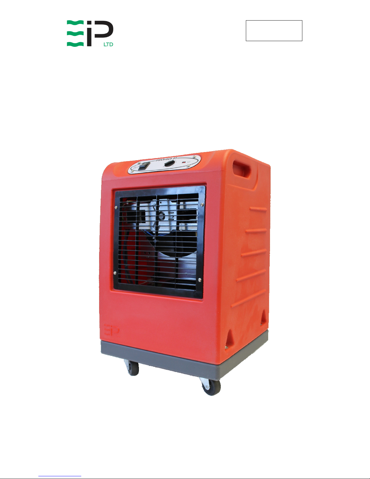
RM40
INDUSTRIAL DEHUMIDIFIER
OWNER’S MANUAL
www.eipl.co.uk
Page 2

Page 2 of 16
Drawing : - TPC470
Issue : - 1
Date : - 09/02/17
RM40
PACKAGE CONTENTS
Item Description Quantity
10187MG-US Dehumidifier 1
3086144 Quick release hose coupling 1
3944110 PVC Tube – 3/8” I/D 7.8M
TPC470 Manual 1
Page 3

Page 3 of 16
Drawing : - TPC470
Issue : - 1
Date : - 09/02/17
INTRODUCTION
Designed for a wide range of applications, the RM40 is a rugged, industrial
unit, which utilizes an energy-efficient compressor and a compact portable
design to provide easy efficient drying.
The fan draws the moist air through the cold evaporator coil, which cools the
air below its dew point. Moisture forms on the evaporator coil and is collected
in the condensate tray, which is equipped with a permanent drain. The cooled
air then passes through the hot condenser coil where it is reheated using the
same energy removed during the cooling phase, plus the additional heat
generated by the compressor. The air is, therefore, discharged from the
dehumidifier at a slightly higher temperature with a lower absolute humidity
than that which entered. Continuous circulation of air through the
dehumidifier gradually reduces the relative humidity within the area.
The RM40 dehumidifier is a rugged, reliable drying unit designed to operate
effectively over a broad range of temperature and humidity conditions. An
active hot gas defrost system, controlled by an electronic timer, guarantees
positive de-icing, thereby optimizing operation at low temperatures.
The unit incorporates a rotational moulded polyethylene shell resilient to
damage caused by rough handling.
Page 4

Page 4 of 16
Drawing : - TPC470
Issue : - 1
Date : - 09/02/17
SPECIFICATIONS
"This product contains fluorinated greenhouse gases covered by the Kyoto Protocol. The
refrigeration system is hermetically sealed.
The Global Warming Potential (GWP) of refrigerants used in products manufactured by Ebac
Industrial Products Ltd is as follows
R134a – 1300
R407c – 1610
For type and weight of refrigerant contained in this unit, please refer to the product data label"
M
ODEL
: 10187MG-US
H
EIGHT
: 24.2” (615 mm)
W
IDTH
: 15” (382 mm)
D
EPTH
: 14.4” (365 mm)
W
EIGHT
: 57lbs (26 kg)
A
IRFLOW
: 88.3CFM (150 M3/Hr)
P
OWER SUPPLY
: 110V/ 60Hz/ 1 ph
F
INISH
:
Rotational Moulded
polyethylene
O
PERATING RANGE
: 37°F – 95°F
R
EFRIGERANT
: R134a (6.1oz (173g))
Page 5

Page 5 of 16
Drawing : - TPC470
Issue : - 1
Date : - 09/02/17
OPERATION
After unpacking, examine all external features to confirm damage-free
shipment. Report all defects and damage at once.
Before connecting it to the mains you should ensure that the humidistat is
turned fully anti-clockwise. Connect to a grounded 15A standard household
electrical outlet then the humidistat control should be turned clockwise until
you hear the unit operate. To protect the compressor, you should allow 5
minutes between switching the dehumidifier off and on again.
OPERATING THE HUMIDISTAT
The humidistat works in a similar way to a central heating thermostat, but
instead of measuring temperature, it measures the amount of moisture in the
air. You may select the level of moisture you require (known as Relative
Humidity) and the unit will operate to achieve that level and then switch off.
As a general guide, the higher the setting the lower the Relative Humidity will
be before the machine switches off. Therefore the machine will operate longer
to achieve this. If the dehumidifier switches off and drying is not complete it is
possible that the humidistat setting is too low and may need increasing.
Conversely, if you no longer have condensation and the unit is still operating,
then the humidistat setting may need reducing.
EMPTYING THE WATER CONTAINER
When the water container is full an internal float mechanism will switch the
unit off. This is indicated by the illumination of the “full” light on the front
control panel. The water container is at the rear of the unit. To empty the
container, carefully remove the water container. When emptied replace
PERMANENT DRAINAGE
When your dehumidifier is to be used constantly in one area, it can be fitted to
drain continuously, eliminating the need to empty the water container. Ideal
when the property is to be left unoccupied.
For this you will need a length of PVC tubing, 10mm internal diameter.
Disconnect your dehumidifier from the power supply before fitting permanent
drainage. Remove the water container; remove the blind grommet on the back
face of the unit and then the blanking bung from the drainage point visible
through the hole. Feed tubing through hole where grommet was located and
onto the visible drain point. Lastly fit the blanking bung to the drain point on
the underside of the drain tray. The water container can be replaced whilst the
drainage kit is in use for safe storage
Page 6

Page 6 of 16
Drawing : - TPC470
Issue : - 1
Date : - 09/02/17
USE OF PERMANENT DRAINAGE
When in use tubing should be run to a suitable drainage point, ensuring that
the tube doesn’t rise above the drain tray, otherwise flooding may occur.
CHECK DEHUMIDIFICATION PROCESS AS FOLLOWS:
1. Place unit on a level surface.
2. Start up unit by switching to “I” and humidistat fully clockwise
3. Check that the compressor is running.
4. Leave the machine running for 15 minutes.
5. Observe the evaporator coils through the rear grille, to confirm frost
formation or weeping.
• If the air temperature is below 25°C, an even coating of frost should
cover the entire evaporator coil.
• If the air temperature is above 25°C, frost and/or droplets of
condensed water should cover the entire evaporator coil.
6. When the unit is operated in ambient of less than 15°C, a defrost cycle
should occur approximately every hour. The exact time is impossible to
predict as the unit is fitted with a temperature sensitive defrost control.
If, after carrying out the above procedures, the unit does not appear to
function properly, refer to the Trouble Shooting section, which follows,
or contact the Factory Service Center.
CAUTION:
DO NOT REMOVE COVERS WHEN UNIT IS IN OPERATION
CAUTION:
ONCE THE UNIT HAS BEEN SWITCHED OFF, WAIT AT
LEAST FIVE MINUTES BEFORE RESTARTING.
Page 7

Page 7 of 16
Drawing : - TPC470
Issue : - 1
Date : - 09/02/17
ROUTINE SERVICE
To ensure continued full efficiency of the dehumidifier, service procedures
should be performed as follows:
1. Clean the surface of the evaporator and condenser coils by blowing the
dirt out from behind the fins with compressed air. Hold the nozzle of the
air hose away from the coil to avoid damaging the fins. Alternatively,
vacuum clean the coils.
2. Check that the fan rotates freely. The fan motor is sealed for life and
therefore does not need oiling.
3. To check the refrigerant charge, run the unit for 15 minutes and observe
the evaporator coil. It should be evenly coated with frost across its
surface. At temperatures above 25°C, the coil may be covered with
droplets of water rather than frost. Partial frosting accompanied by
frosting of the thin capillary tubes, indicates loss of refrigerant gas or low
charge.
4. Check all wiring connections, including mains cable for damage or loose
connections.
5. In order to check the defrost operation, the unit needs to be operated in
an ambient temperature of less than 15°C for at least 1 hour. When
operated In this condition the unit should defrost at least once every
hour. The defrost mode can be monitored by observing the ice melting
on the coil face, prior to defrost the face will show a white coating of
frost, which should clear during defrost
I
F ANY OF THE PRECEDING PROBLEMS OCCUR, CONTACT THE EBAC
S
ERVICE CENTER PRIOR TO CONTINUED OPERATION OF THE UNIT TO
PREVENT PERMANENT DAMAGE.
WARNING:
ENSURE THAT THE POWER CORD TO THE MACHINE HAS BEEN
DISCONNECTED BEFORE CARRYING OUT ROUTINE SERVICE. THE
SERVICING AND REPAIR OF THIS UNIT SHOULD ONLY BE CARRIED
OUT BY A SUITABLY QUALIFIED PERSON.
WARNING:
DO NOT STEAM CLEAN REFRIGERATI
ON COILS
Page 8

Page 8 of 16
Drawing : - TPC470
Issue : - 1
Date : - 09/02/17
REPAIRS
1. Should an electrical component fail, consult the Factory Service Center
to obtain the proper replacement part.
2. If refrigerant gas is lost from the machine, it will be necessary to use a
refrigeration technician to correct the fault. Contact the Factory Service
Center prior to initiating this action.
Any competent refrigeration technician will be able to service the
equipment. The following procedure must be used:
a. The source of the leak must be determined and corrected.
b. The machine should be thoroughly evacuated before recharging.
c. The unit must be recharged with refrigerant measured accurately
by weight.
d. For evacuation and recharging of the machine, use the crimped
and brazed charging stub attached to the side of the refrigerant
compressor.
The charging stub should be crimped and rebrazed after servicing.
N
EVER
allow permanent service valves to be fitted to any part of the
circuit. Service valves may leak causing further loss of refrigerant
gas.
3. The refrigerant compressor fitted to the dehumidifier is a durable unit
that should give many years of service. Compressor failure can result
from the machine losing its refrigerant gas. The compressor can be
replaced by a competent refrigeration technician.
Failure of the compressor can be confirmed by the following procedure:
a. Establish that power is present at the compressor terminals using a
voltmeter.
b. With the power disconnected, check the continuity of the internal
winding by using meter across the compressor terminals. An open
circuit indicates that the compressor should be replaced.
c. Check that the compressor is not grounded by establishing that a
circuit does not exist between the compressor terminals and the
shell of the compressor.
Page 9

Page 9 of 16
Drawing : - TPC470
Issue : - 1
Date : - 09/02/17
TROUBLESHOOTING
S
YMPTOM
C
AUSE
R
EMEDY
Unit inoperative
1. No power to unit
2. Mains cable damaged.
1. Check the power from
power supply panel.
2. Contact the Factory
Service Center
Little or no airflow
1. Fan motor burnt out
2. Dirty refrigeration coils
3. Loose electrical wiring
1. Replace the fan motor
2. See Routine Maintenance
Section
3. Check the wiring diagram
to find fault and repair
Little or no water
extraction
1. Insufficient air flow
2. Compressor fault
3. Loss of refrigerant gas
1. Check all of the above
2. Contact the Factory
Service Center
3. Contact the Factory
Service Center
Little or no defrost
when required
1. Faulty timer
2. Faulty by-pass valve
1. Contact the Factory
Service Center
2. Contact the Factory
Service Center
Unit vibrates
excessively
1. Loose compressor
2. Damaged fan
1. Tighten the nuts on the
compressor mounts
2. Replace fan
Water flooding inside
the machine
1. Drain pipe blocked/frozen
2. Drain pipe too high
3. Crimped or blocked tubing
1. Clear the obstruction
2. Ensure that no section of
the drain hose is above the
level of the water outlet
3. Straighten, clear, or replace
tubing
Spare parts available online
www.EIPLDIRECT.com
Page 10
Page 10 of 16
Drawing : - TPC470
Issue : - 1
Date : - 09/02/17
RM40
SPARE PARTS LIST
N
UMBER
D
ESCRIPTION
P
ART
N
UMBER
Q
UANTITY
1 Timer 1617990 1
2 Condenser coil 2131147 1
3 Evaporator coil 1018611 1
4 Drain tray 2018705 1
5 Filter 1019712 1
6 Capillary 3014250 1.64ft
7 Solenoid valve 3020836 1
8 Filter dryer 3020937 1
9 Solenoid coil 3030451 1
10 On/Off switch 3035914 1
11 Fan Motor 3035773 1
12 Fan Blade 3040181 1
13 Castor 3050205 4
14 Compressor 3022147 1
15 Water Container Assy 1137907 1
16 Bucket Micro Switch 3033033 1
17 Humidistat Knob 2018644 1
18 Bucket Full Lens 3032271 1
19 Bucket Full Light 3036636 1
20 Humidistat 3035158 1
21 Mains Cable 2141095 1
22 Front Grille 2018704 1
Page 11

Page 11 of 16
Drawing : - TPC470
Issue : - 1
Date : - 09/02/17
WARNINGS
This appliance can be used by children from 8 years and above and persons
with reduced physical, sensory or mental capabilities or lack of experience
and knowledge if they have been given supervision or instruction concerning
use of the application in a safe way and understand the hazards involved.
Children shall not play with the appliance.
Cleaning and user maintenance shall not be made by children without
supervision.
If the SUPPLY CORD is damaged, it must be replaced by the manufacturer,
its service agent or similarly qualified person in order to avoid hazard.
This product contains fluorinated greenhouse gases covered by the Kyoto
Protocol. The refrigeration system is hermetically sealed.
The Global Warming Potential (GWP) of refrigerants used in products
manufactured by Ebac Industrial Products Ltd is as follows
R134a – 1300
R407c – 1610
For type and weight of refrigerant contained in this unit, please refer to the
product data label
Due to the high pressures within the refrigeration circuit, under no
circumstances must direct heat be applied to the evaporator coil in an attempt
to remove the build-up of ice.
No attempt should be made to cut open any part of the refrigeration circuit
due to high pressures and gas involved.
If the unit is switched off at the mains power supply for any reason, the unit
must be allowed to stand at rest for at least three minutes before restarting.
For correct installation and operation the unit inlet and outlet must have a
clearance of 0.5M from all adjacent surfaces and or structures.
Page 12

Page 12 of 16
Drawing : - TPC470
Issue : - 1
Date : - 09/02/17
LIMITED WARRANTY
Our products carry a one-year unconditional warranty against any defects in
workmanship or material. This warranty will cover all parts and labor required
to repair your Ebac product. This warranty is invalid if the unit has been
abused, damaged, whether intentional or accidental, or if any modifications
have been made to the unit.
THE FOREGOING WARRANTY IS EXCLUSIVE AND IS ISSUED IN LIEU OF
ALL OTHER WARRANTIES (WHETHER WRITTEN, ORAL, OR IMPLIED)
INCLUDING THE WARRANTY OF MERCHANTABILITY AND THE
WARRANTY OF FITNESS FOR A PARTICULAR PURPOSE. EBAC
INDUSTRIAL PRODUCTS, INC. DISCLAIMS ANY LIABILITY FOR
CONSEQUENTIAL DAMAGES, LOST PROFITS, OR INCIDENTAL
DAMAGES FOR BREACH OF ANY WRITTEN OR IMPLIED WARRANTY
WITH RESPECT TO THE FOREGOING DESCRIBED MERCHANDISE.
For Your Records: Model:____________________
S/N:______________________
Date Received:______________
SAVE THIS SECTION FOR YOUR RECORDS
CLIP AND RETURN THIS CARD
PLEASE NOTE
WARRANTY REGISTRATION
To ensure that your
Ebac Dehumidifier is
accorded the full
coverage provided by
this warranty, please
complete and mail this
card at your earliest
convenience.
Thank You
DATE
MODEL ___________ S/N ________________ RECEIVED ________________
OWNER __________________________________________________________
ADDRESS ________________________________________________________
CITY __________________________ STATE ________ ZIP _______________
COMMENTS ______________________________________________________
_________________________________________________________________
Ebac Industrial Products.
700 Thimble Shoals Boulevard, Suite 109, Newport News, Virginia. 23606-2575
Page 13

Page 13 of 16
Drawing : - TPC470
Issue : - 1
Date : - 09/02/17
Page 14

Page 14 of 16
Drawing : - TPC470
Issue : - 1
Date : - 09/02/17
Page 15

Page 15 of 16
Drawing : - TPC470
Issue : - 1
Date : - 09/02/17
Page 16

Page 16 of 16
Drawing : - TPC470
Issue : - 1
Date : - 09/02/17
UK Head Office
Ebac Industrial Products Ltd
St Helens Trading Estate
Bishop Auckland
County Durham
DL14 9AD
Tel: +44 (0) 1388 664400
Fax: +44 (0) 1388 662590
www.eipl.co.uk
American Sales Office
Ebac Industrial Products Inc
700 Thimble Shoals Blvd.
Suite 109, Newport News
Virginia, 23606-2575
USA
Tel: +01 757 873 6800
Fax: +01 757 873 3632
www.ebacusa.com
German Sales Office
Ebac Industrial Products Ltd.
Gartenfelder Str. 29-37
Gebäude 35
D-13599, Berlin
Germany
Tel: +49 3043 557241
Fax: +49 3043 557240
www.eip-ltd.de
 Loading...