

EIPL EBAC PD200 Owner's Manual

PD200 OWNERS MANUAL
Drawing No. :- TPC369
Issue :- 5
Date :-
24/11/16
EBAC MODEL PD200
INDUSTRIAL DEHUMIDIFIER
OWNER’S MANUAL
www.eipl.co.uk

PD200 OWNERS MANUAL
Drawing No. :- TPC369
Issue :- 5
Date :-
24/11/16
UNPACKING
Carefully remove the PD200 dehumidifier unit from its transit box and visually check for signs
of transit damage. If there is evidence of damage DO NOT attempt to operate the unit, call your
supplier for advice. Do not discard the packing, it will be useful when transporting the
dehumidifier unit in the future.
INTRODUCTION
The Ebac PD200 industrial dehumidifier removes moisture from the air through the refrigeration
process.
The Ebac PD200 is basically comprised of:
1) A compressor
2) A refrigerant evaporator coil
3) A refrigerant condenser coil
4) One circulation fan
5) A remote humidistat
6) A cabinet to house the above components
The fan draws the moist air through the cold evaporator coil which cools the air below its dew
point. Moisture forms on the evaporator coil and is collected in the condensate tray which is
equipped with a permanent drain. The cooled air then passes through the hot condenser coil
where it is reheated using the same energy removed during the cooling phase, plus the additional
heat generated by the compressor. The air is therefore discharged from the dehumidifier at a
slightly higher temperature with a lower absolute humidity than with which it entered.
Continuous circulation of air through the dehumidifier gradually reduces the relative humidity
within the area.
The PD200 dehumidifier is a rugged, reliable drying unit designed to operate effectively over a
broad range of temperature and humidity conditions.
The PD200 dehumidifier uses a remotely mounted adjustable humidistat to enable you to select
the level of dryness.

PD200 OWNERS MANUAL
Drawing No. :- TPC369
Issue :- 5
Date :-
24/11/16
SPECIFICATIONS
MMMM
ODEL
ODELODEL
ODEL
::::
Ebac PD200
HHHH
EIGHT
EIGHTEIGHT
EIGHT
::::
441mm
WWWW
IDTH
IDTHIDTH
IDTH
::::
683mm
DDDD
EPTH
EPTHEPTH
EPTH
::::
658mm
WWWW
EIGHT
EIGHTEIGHT
EIGHT
::::
70.5Kg
AAAA
IR
IRIR
IRFLOW
FLOWFLOW
FLOW
::::
Low 450 M3/hr
High 850 M3/hr
HHHH
ORSEPOWER
ORSEPOWERORSEPOWER
ORSEPOWER
::::
3
PPPP
OWER
OWER OWER
OWER
SSSS
UPPLY
UPPLYUPPLY
UPPLY
::::
230V/50Hz/1ph
FFFF
INISH
INISHINISH
INISH
::::
Powder-coated Epoxy
RRRR
EFRIGERANT
EFRIGERANT EFRIGERANT
EFRIGERANT
TTTT
YPE
YPEYPE
YPE
/Q
/Q/Q
/Q
TY
TYTY
TY
::::
R407c
PD200 OWNERS MANUAL
Drawing No. :- TPC369
Issue :- 5
Date :-
24/11/16
INSTALLATION
POSITIONING:
Position the dehumidifier unit in the center of the room to be conditioned if at all possible.
However if a damp patch is particularly apparent the outlet grille should be pointed towards it if
possible.
This unit can also be used in a duct system where applicable, please see the diagrams on the
following pages which identify the overall sizes of the unit and also the mounting points.
NOTE: Both inlet grille and outlet grille of the dehumidifier unit must have clear space around
them and not be obstructed in anyway. For correct installation and operation the unit inlet and
outlet must have a clearance of 0.5M from all adjacent surfaces and or structures.
Before connecting this unit to the relevant power supply the following must be carried out.
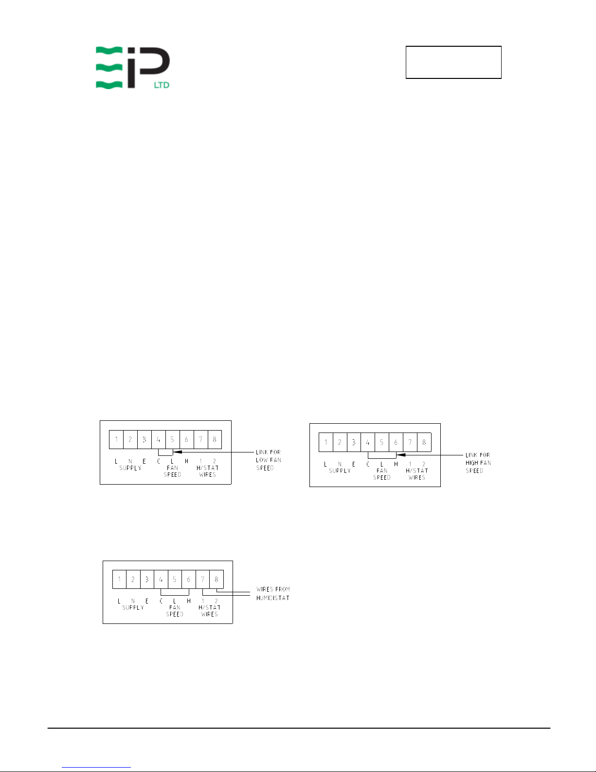
Selecting the correct fan speed – The PD200 has a low fan speed and a high fan speed and the
required speed must be chosen before installation. To select the correct fan speed firstly remove
the air inlet cover via the 10off M4 hex head bolts, then remove the electrical box cover via the
4off M4 hex head bolts. Once the electrical box cover is removed the supplied link wire must be
wired between either the ‘C’ and ‘L’ or the ‘C’ and ‘H’ terminals on the terminal block. This is
shown below.
Before the unit will switch on it must have a low voltage humidistat wired into it with the NC
contacts wired to the terminal block inside the electrical box as shown below.
 Loading...