

EIPL CD100E Owner's Manual
Page 1 of 16
Drawing : - TPC181
Issue : - 11
Date : - 24/11/16
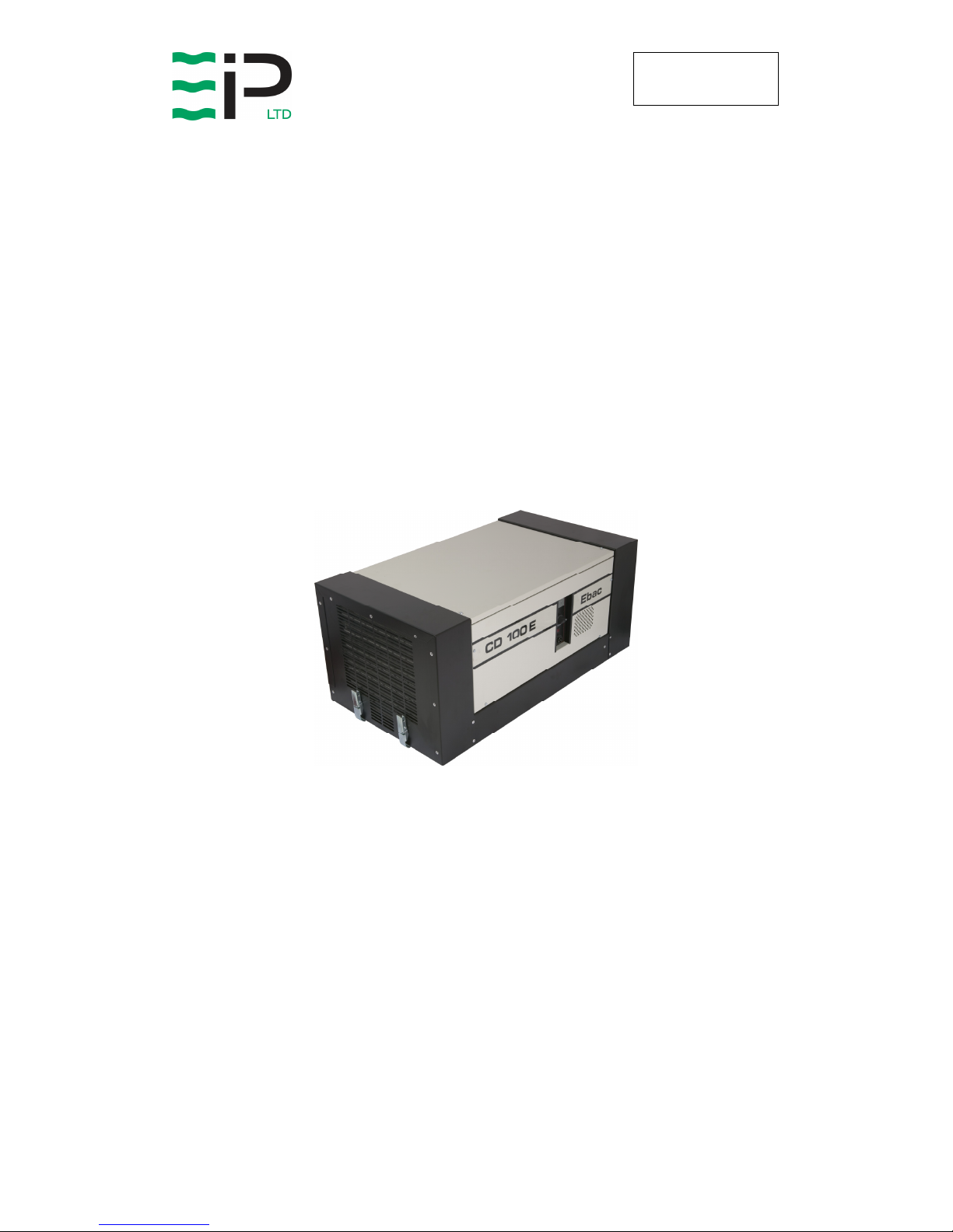
CD100E
INDUSTRIAL DEHUMIDIFIER
OWNER’S MANUAL
www.eipl.co.uk

Page 2 of 16
Drawing : - TPC181
Issue : - 11
Date : - 24/11/16
UNPACKING
Carefully remove the CD100 dehumidifier unit from its transit box and visually
check for signs of transit damage. If there is evidence of damage DO NOT
attempt to operate the unit, call your supplier for advice. Do not discard the
packing; it will be useful when transporting the dehumidifier unit in the future.
INTRODUCTION
Dehumidifiers remove moisture from the air that is circulating through the unit.
The resulting reduction of relative humidity helps prevent rust, rot, mould,
mildew and condensation within the room, shelter or other enclosed spaces
where the dehumidifier is used.
A dehumidifier consists of a motor-compressor unit, a refrigerant condenser,
an air circulating fan, a refrigerated evaporator, a means for collecting and
disposing of the condensed moisture and a cabinet to house these
components.
The fan draws the moist room air through the cold evaporator coil which cools
the air below its dew point. Moisture forms on the evaporator and is collected
in the condensate tray then lead away to a permanent drain. The cooled air
then passes through the hot condenser, where it is re-heated with the same
energy removed during the cooling phase and the addition heat derived from
the compressor. The air is therefore discharged into the room at a slightly
higher temperature but at a lower relative humidity than that at which it
entered the unit. Continuous circulation of room air through the dehumidifier
gradually reduces the relative humidity of the room.
The CD100 dehumidifier is a rugged reliable drying unit designed to operate
effectively over a broad range of temperature and humidity conditions. A
powerful and reliable active hot gas defrost system, controlled by an
electronic timer, guarantees positive de-icing, thereby optimizing at low
temperatures.
The unit incorporates a welded steel chassis and is finished in vinyl coated
steel covers for resilience to damage caused by rough handling.

Page 3 of 16
Drawing : - TPC181
Issue : - 11
Date : - 24/11/16
SPECIFICATIONS
"This product contains fluorinated greenhouse gases covered by the Kyoto Protocol. The
refrigeration system is hermetically sealed.
The Global Warming Potential (GWP) of refrigerants used in products manufactured by Ebac
Industrial Products Ltd is as follows
R134a – 1300
R407c – 1610
For type and weight of refrigerant contained in this unit, please refer to the product data label"
M
ODEL
: CD100E
H
EIGHT
: 400mm
W
IDTH
: 900mm
D
EPTH
: 500mm
W
EIGHT
: 75 Kg
A
IRFLOW
: 510 cu.m/hr
P
OWER
1.5Kw (max)
P
OWER SUPPLY
:
220V/240V, 1p,
50Hz/60Hz.
F
INISH
: Vinyl Coated Steel
M
OBILITY
:
Choice of Mobility
Aids – Wheels of
Skid Handle
R
EFRIGERANT TYPE/QTY
: R407c (0.540Kg)

Page 4 of 16
Drawing : - TPC181
Issue : - 11
Date : - 24/11/16
INSTALLATION
POSITIONING:
Position the dehumidifier unit in the center of the room to be conditioned if at
all possible. However if a damp patch is particularly apparent the outlet grille
should be pointed towards it.
NOTE: Both inlet grille and outlet grille of the dehumidifier unit must have
clear space around them and not be obstructed in anyway. For correct
installation and operation the unit inlet and outlet must have a clearance of
0.5M from all adjacent surfaces and or structures.
WIRING:
Connect the power cord of the dehumidifier to a suitable single phase, fused
power supply. As follows:-
Brown Live
Blue Neutral
Green/Yellow Earth (ground)
ALARM WIRING:
Plug L (Normally Open Contacts)
Plug N (Close on Humidity Rise)
Plug E (Earth)
DRAINAGE:
Connect a 15mm inside diameter hose to the condensate outlet pipe
(positioned centrally, beneath the air inlet grille). Secure the hose using a
worm drive clip. The hose should at no point be raised higher than the outlet
pipe. The hose should be ran to a permanent drain. Failure to observe this
requirement will result in flooding of the dehumidifier unit. Ensure the drain
tube heater tape is inserted the full length of the drain tube.
OPTIONAL
The CD100 may also be fitted with a water pump capable of discharging the
condensate a vertical height of 30ft. The water can, therefore, be discharged
into a drain some distance away.

Page 5 of 16
Drawing : - TPC181
Issue : - 11
Date : - 24/11/16
OPERATION
The operation of the dehumidifier is to remove moisture from the air by having
it condense on the cool tubes of the evaporator coil. The air then passes over
the hot condenser and returns to the conditioned space slightly warmer and at
reduced moisture content. To concentrate drying all doors and windows
should be kept closed.
AIR MOVING SYSTEM:
Air is drawn in through the inlet grille at the rear of the dehumidifier (below the
handle) and over the two heat exchanges (evaporator/condenser coils) under
the influence of the axial fan, which is driven by the motor. The operation of
the fan motor is to run continuously whenever power is supplied to the
dehumidifier. The fan motor used in the dehumidifier unit is induction
protected i.e. the motor is able to take stalled current without burning out the
motor windings.
TEST FOR CORRECT OPERATION:
1. Set the adjustment humidistat to maximum
2. Switch the machine to the on position; this will result in the compressor
starting to run and the fan blade starting to rotate.
3. When the compressor has been running for twenty minutes the coils
located above the drain tray will be evenly coated in frost. (If the
temperature is above 25ºC the coils will be covered in water).
4. After the machine has been running for approximately fifty minutes the
unit will automatically enter defrost. The defrost cycle lasts for
approximately three minutes; this will result in the frost on the coils
melting and dripping into the drainage tray.
5. After the defrost has finished the machine will return to normal operation.
6. Ensure the condensate drains away from the machine.
WARNING:
DO NOT RUN THE MACHINE WITHOUT THE COVERS IN
PLACE FOR ANY LONGER THAN NECESSARY. DO NOT
REMOVE / REPLACE THE COVERS WITH THE POWER ON
 Loading...