

EIPL BD12 Owner's Manual
Page 1 of 16
Drawing : - TPC142
Issue : - 4
Date : - 24/11/16
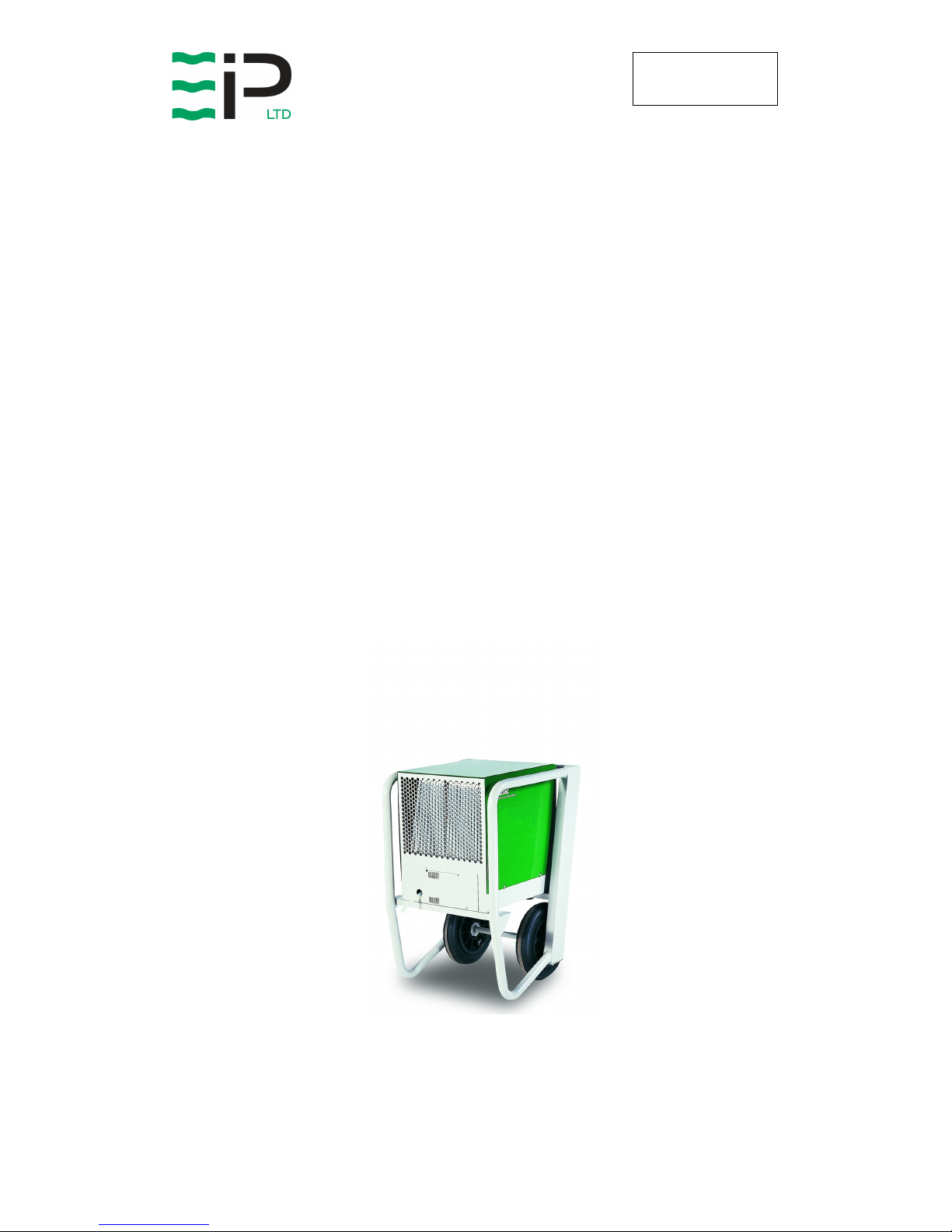
BD12
INDUSTRIAL DEHUMIDIFIER
OWNER’S MANUAL
BD12 PRODUCT RANGE
1026500 1ph 110/230v 50Hz UK
1026600 1ph 230v 50Hz UK
1026700 1ph 230v 50 Hz Germany
1026800 1ph 230v 50Hz France
1026900 1ph 115v 60 Hz North America
www.eipl.co.uk

Page 2 of 16
Drawing : - TPC142
Issue : - 4
Date : - 24/11/16
UNPACKING
Carefully remove the BD12 dehumidifier from its transit packing and visually
check for signs of transit damage. If there is evidence of damage DO NOT
attempt to operate the unit call you supplier for advice.
INTRODUCTION
Dehumidifiers remove moisture from the air that is circulating through the unit.
The resulting reduction of relative humidity helps prevent rust, rot, mould,
mildew and condensation within the room, or other enclosed spaces where
the dehumidifier is used.
A dehumidifier consists of a motor-compressor unit, a refrigerant condenser,
an air circulating fan, a refrigerated surface, a means of collecting and
disposing of the condensed moisture and a cabinet to house these
components.
The fan draws moist air over the refrigerated surface and cools it below its
dew point, removing the moisture which is collected and lead away. The cool
air then passes the hot condenser, where it is reheated. With the addition of
other radiated heat the air is discharged into the room at a higher temperature
but lower relative humidity than when the air entered the unit. Continuous
circulation of the room air through the dehumidifier unit gradually reduces the
relative humidity in the room.
The BD12 dehumidifier is a robust, unit designed to control the humidity in the
enclosed space in which it is placed.
The unit is thermal protected and will switch off for a period of time if the
maximum operating temperature of 35ºC is exceeded.
The BD12 dehumidifier unit is normally supplied, with a trolley, which is to aid
its mobility from room to room. It is possible, by removing the four M8 bolts
which fix the unit to the trolley, to have a freestanding unit for longer term
applications, or by mounting the unit on the wall, by means a suitable bracket
for permanent applications.
The gas which is used inside the hermetically sealed refrigeration circuit is
R22, which has been passed as a non ozone depletion factor by the Montreal
Protocol.
BUT under no circumstances should this gas be released into the
atmosphere, the unit should be serviced by trained personnel who will reclaim
any of the unwanted gas.

Page 3 of 16
Drawing : - TPC142
Issue : - 4
Date : - 24/11/16
BD12 DEHUMIDIFIER
SPECIFICATION
H
EIGHT
: 900 mm
W
IDTH
: 575 mm
D
EPTH
: 632 mm
W
EIGHT
: 80 kg
A
IRFLOW
: 700 m3/hr
P
OWER
: 1500 w
P
OWER SUPPLY
:
110/230v 1ph
50hz; 115v 1ph
60hz
F
INISH
: Epoxy powder
M
OBILITY
:
Two wheeled
trolley
E
FFECTIVE VOLUME
: 572 cfm
R
EFRIGERANT TYPE
: R22
R
EFRIGERANT
C
HARGE
:
0.700 kg
"This product contains fluorinated greenhouse gases covered by the Kyoto Protocol. The
refrigeration system is hermetically sealed.
The Global Warming Potential (GWP) of refrigerants used in products manufactured by Ebac
Industrial Products Ltd is as follows
R134a – 1300
R407c – 1610
For type and weight of refrigerant contained in this unit, please refer to the product data label"

Page 4 of 16
Drawing : - TPC142
Issue : - 4
Date : - 24/11/16
INSTALLATION
POSITIONING
Position the dehumidifier unit in the centre of the room, or area to be
conditioned if it all possible. However, if a damp patch is particularly apparent
the outlet grille should be directed towards it.
Note: Both the inlet and outlet grille of the dehumidifier unit must have clear
space around them and not be obstructed in anyway.
WIRING
Connect the power mains cable/plug of the dehumidifier to a 15 amp power
supply. As follows:
110/230 Volt supply
Brown Live
Blue Neutral
Green/Yellow Earth (Ground)
115 Volt Supply
White Live
Black Neutral
Green/Yellow Earth (Ground)
STARTING PROCEDURE
With the dehumidifier unit connected to the correct power supply, move the
switch (on the front of the unit) to ON position, both the compressor and the
fan motor will start.
Note: For units fitted with “Low voltage protection” see under the Standard
features section
DRAINAGE
Connect a 10mm inside diameter hose to the condensate outlet pipe
(positioned beneath the air inlet grille). Secure the hose (with the clip
provided). The hose should at no point be raised higher than the outlet pipe in
the condensate drainage tray. The hose should be ran to a permanent drain.
Failure to observe this requirement will result in flooding of the dehumidifier
unit.

Page 5 of 16
Drawing : - TPC142
Issue : - 4
Date : - 24/11/16
OPERATION
GENERAL OPERATION
The operation of the dehumidifier is to remove moisture from the air by having
it condense on the cold tubes of the evaporator coil. The air then passes over
the hot condenser coil and returns to the conditioned space slightly warmer
and dryer than when it entered the dehumidifier unit.
AIR MOVING SYSTEM
Air is drawn in through the inlet grille of the dehumidifier unit and over the two
heat exchanges (Evaporator/Condenser coils) under the influence of the axial
fan which is driven by the motor. The operation of the fan motor is to run
continuously whenever power is supplied to the dehumidifier unit. The fan
motor used in the dehumidifier unit is induction protected i.e. the motor is able
to take stalled current without burning out the motor windings.
REFRIGERATION CIRCUIT
CONDITIONING OPERATION
The basic operation of a refrigeration system is to boil liquid refrigerant in the
evaporator coil, and re-condense it into a liquid in the condenser coil.
Liquid refrigerant is metered out from the capillary tubes into the evaporator
coil and under the influence of the suction port of the compressor; it boils or
evaporates into gas. In order to change its state from liquid into gas the
refrigerant requires a large amount of heat. This is gained by the tubes of the
evaporator coil which thereby become sufficiently cold to fall below the dew
point of the air which is passing over them. The refrigerant gas is taken into
the compressor and discharges into the condenser coil as high pressure gas.
The heat which was used to evaporate the refrigerant at low pressure is still
present and is shown by a rise in temperature of the gas as it leaves the
compressor. As heat is removed from the hot condenser coil by the air flowing
over it, the refrigerant gas is condensed back into liquid. It then leaves the
condenser coil and passes through the filter dryers before continuing the cycle
via the capillary tubes. In this way heat which is taken from the air as it passes
over the evaporator coils is re-introduced into the same air flow as it passes
over the condenser coil. However, since the temperature of the evaporator
coil is below the dew point of the air. Its moisture content is reduced and
thereby the air passing out to the conditioned space is reduced in relative
humidity (dryer air).
 Loading...