

Page 1
Page 1 of 12
Drawing : - TPC159
Issue : - 4
Date : - 24/11/16
LD
LDLD
LD----82
8282
82
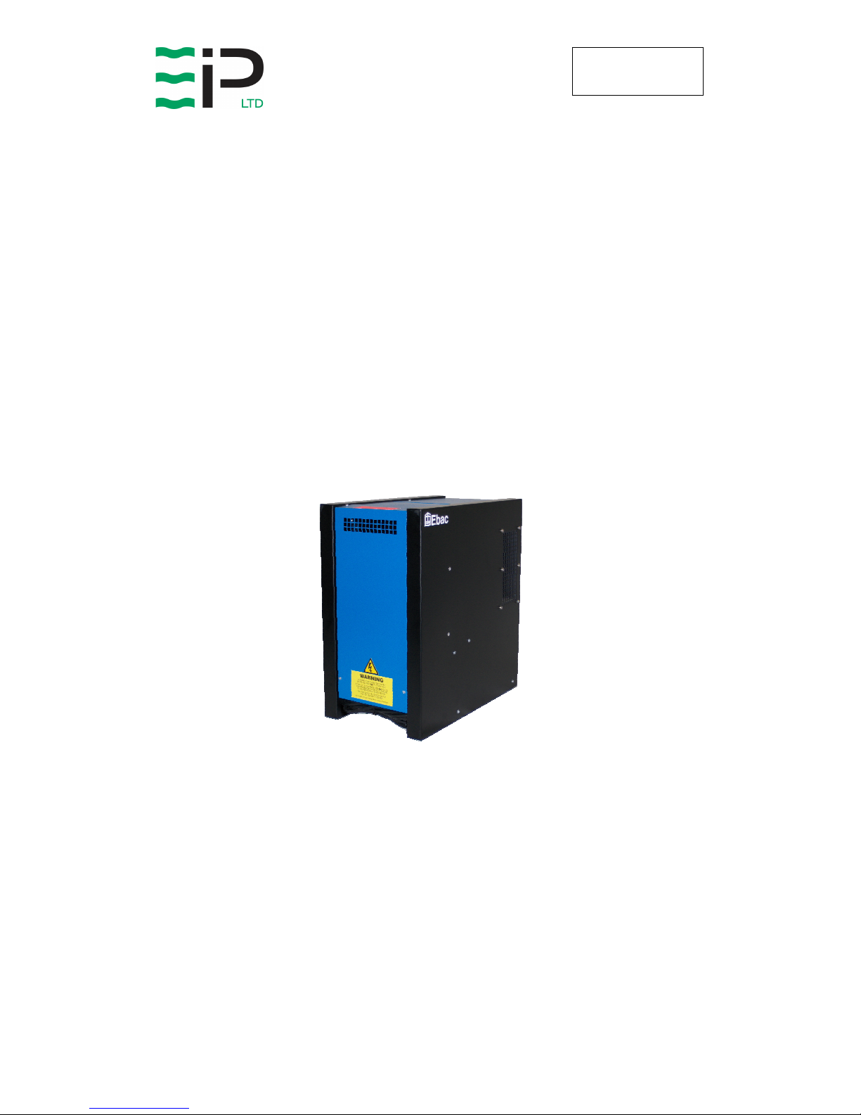
DEHUMIDIFIER PROCESS
DEHUMIDIFIER PROCESSDEHUMIDIFIER PROCESS
DEHUMIDIFIER PROCESS DRYER
DRYERDRYER
DRYER
(1320500)
(1320500)(1320500)
(1320500)
OWNER’S MANUAL
OWNER’S MANUALOWNER’S MANUAL
OWNER’S MANUAL
www.eipl.co.uk
Page 2

Page 2 of 12
Drawing : - TPC159
Issue : - 4
Date : - 24/11/16
UNPACKING
Carefully remove the LD-82 dehumidifier process dryer and the Universal
Controller from its transit box and visually check for signs of transit damage. If
there is evidence of damage DO NOT attempt to operate the units, call your
supplier for advice. Do not discard the packing; it will be useful when
transporting the dehumidifier unit in the future.
INTRODUCTION
The LD-82 dehumidifier process dryer is supplied complete with a Universal
Controller (STC1) ready for installation into a pre-built drying chamber.
Instructions for the building of the drying chamber can be supplied by Ebac
Ltd.
Ask for the Ebac Technical Publication (TP 132), “Wood Drying with the Ebac
range of small scale wood dryers”
The LD-82 dehumidifier process dryer removes moisture from the air that is
circulating through the unit.
The LD-82 dehumidifier process dryer requires no previous experience with
drying as it is simple to install and operate. The process dryer is energy
efficient, quiet to operate and will cause no pollution problems.
The Ebac method of drying is a process of dehumidification. The LD-82
dehumidifier process dryer is placed in a sealed chamber with the produce
required to be dried. By continually removing moisture from the air which is
circulated through the product stack, the LD-82 process dryer creates a
condition in which the product progressively releases its moisture under the
controlled conditions.
As the process is one of re-circulation of the same air (within the chamber),
minimal energy loss occurs and therefore the running costs are kept low.
Capital costs are also kept low with the Ebac LD-82 dehumidifier process
dryer. However, the dried product is of the highest quality with consistent and
even moisture content.
Because the drying process is carried out within the controlled conditions, the
repeatability of each batch of product being dried is always of the same high
quality and moisture content.
The LD-82 dehumidifier process dryer themselves are easily installed in the
ready made chamber of the requisite size.
Page 3

Page 3 of 12
Drawing : - TPC159
Issue : - 4
Date : - 24/11/16
The LD-82 dehumidifier process dryer consists of a motor-compressor unit, a
refrigerant condenser, air circulating fans, a refrigerated surface, and a means
of collecting and disposing the condensed moisture and a cabinet to house
these components.
The fan draws air through the refrigerated surface and cools it below its dew
point, removing moisture which is collected and led away. The cool air then
passes the hot condenser, where it is reheated (with the same energy
removed during the cooling phase). With the addition of other radiated heat
and extra heat (if required), from an electrical heater bank, the air is
discharged into the chamber at a higher temperature but lower relative
humidity than when the air first entered the process drying unit. Continuous
circulation of the chamber air through the LD-82 dehumidifier process dryer
gradually (under controlled conditions), reduces the relative humidity, thereby
drying the product.
Page 4

Page 4 of 12
Drawing : - TPC159
Issue : - 4
Date : - 24/11/16
SPECIFICATIONS
"This product contains fluorinated greenhouse gases covered by the Kyoto Protocol. The
refrigeration system is hermetically sealed.
The Global Warming Potential (GWP) of refrigerants used in products manufactured by Ebac
Industrial Products Ltd is as follows
R134a – 1300
R407c – 1610
For type and weight of refrigerant contained in this unit, please refer to the product data label"
M
ODEL
:
LD-82
H
EIGHT
: 600 mm
W
IDTH
: 315 mm
D
EPTH
: 550 mm
W
EIGHT
: 37 Kg
A
IRFLOW
:
600 m3/hr
O
PERATING TEMP RANGE
: 20-55°C
P
OWER SUPPLY
: 230V, 1 ph, 50Hz
P
OWER (DRYING
): 350W
P
OWER (HEATING
): 350W
M
AX WATER EXTRACTION
: 13 l/24hr
F
INISH
: epoxy coating
E
FFECTIVE VOLUME
: 200M3
R
EFRIGERANT TYPE/QTY
: R134a (250g)
Page 5

Page 5 of 12
Drawing : - TPC159
Issue : - 4
Date : - 24/11/16
INSTALLATION
POSITIONING:
Position the LD-82 dehumidifier process dryer in the chamber as shown and
instructed (see TP 132). It is advisable to ensure that access can be made to
the process drying unit even when the entire product to be dried is in place.
The Universal Controller (UC-2) should also be positioned for ease of access
on the outside of the chamber or adjacent wall.
WIRING:
Connect the LD-82 dehumidifier process dryer to a 230V, 1 phase, 50Hz
supply as follows:-
Brown Live
Blue Neutral
Green/Yellow Earth (ground)
DRAINAGE:
Connect a 15mm inside diameter hose to the condensate outlet pipe
(positioned on the drainage tray, beneath the evaporator coil). Secure the
hose using a worm drive clip. The hose should at no point be raised higher
than the outlet pipe. The hose should be ran to a permanent drain. Failure to
observe this requirement will result in flooding of the LD-82 dehumidifier
process dryer.
Page 6

Page 6 of 12
Drawing : - TPC159
Issue : - 4
Date : - 24/11/16
OPERATION
The LD-82 dehumidifier process dryer is a basic refrigeration drying unit. A
control system, the Universal Controller (UC-2), is required for each of the LD82 dehumidifier process dryers to be used in each chamber for the drying
process.
The operation of the LD-82 dehumidifier process dryer is to remove moisture
from the air by having it condense on the cold tubes of the evaporator coil.
The air then passes over the hot condenser coil and returns to the chamber
slightly warmer and dryer than when it entered the process drying unit.
AIR MOVING SYSTEM:
Air is drawn into the LD-82 dehumidifier process unit at the base of the
dehumidifier and over the two heat exchanges (evaporator/condenser coils)
under the influence of the axial fan, which is driven by the motor. The
operation of the fan motor is to run continuously whenever power is supplied
to the dehumidifier. The fan motors used in the LD-82 dehumidifier process
dryer unit are induction protected i.e. the motor is able to take stalled current
without burning out the motor windings.
HIGH TEMPERATURE CUT OUT:
The LD-82 dehumidifier process dryer unit has been designed to work in
ambient temperatures between 20ºC and 60ºC. Should the temperature in the
chamber become excessive a thermostat within the compressor casing will
open and dehumidifying will stop, until the thermostat resets itself?
HEATER ELEMENT PROTECTION DEVICE:
The LD-82 dehumidifier process dryer unit has been fitted with heater
elements. This heat is used intermittently during the drying cycle (under
controlled conditions), to provide the heat necessary to raise or maintain the
temperature of the chamber. The heater element is protected by a
temperature sensitive device. If for any reason the temperature rises above
the pre-set (70°C) safety point, the power to the unit will be switched off.
Page 7

Page 7 of 12
Drawing : - TPC159
Issue : - 4
Date : - 24/11/16
WARNING:
• Due to the high pressures within the refrigeration circuit, under no
circumstances must direct heat be applied to the evaporator coil in an
attempt to remove the build up of ice.
• No attempt should be made to cut open any part of the refrigeration circuit
due to high pressures and gas involved.
•
If the unit is switched off at the mains power supply for any reason, the unit
must be allowed to stand at rest for at least three minutes before
restarting. Failure to do so may cause the unit to blow the fuses owing to
the compressor due to there being a refrigerant imbalance.
Page 8

Page 8 of 12
Drawing : - TPC159
Issue : - 4
Date : - 24/11/16
ROUTINE SERVICE
To ensure continued full efficiency of the process dryer unit, maintenance
procedures should be performed as follows:
Removal of the three covers, by means of the four screws in the corners of
each cover, will allow access for all the maintenance to be carried out.
1. Clean the surface of the evaporator and condenser coils by blowing
the dirt out from behind the fins with compressed air. Hold the nozzle
of the air hose away from the coil (approx 6”/150mm) to avoid
damaging the fins. Alternatively, vacuum clean the coils.
2. Check that the fan is firmly secured to the motor shaft and that the
fan blade is positioned centrally inside the housing and that it
rotates freely. The motor is sealed for life and therefore does not
require lubrication.
3. To check the refrigerant charge, run the unit for 15/20 minutes and
briefly remove the cover. The evaporator coil should be evenly frost
coated across its surface. At temperatures above 20°C, the coil
may be covered with droplets of water rather than frost. Partial
frosting accompanied by frosting of the thin capillary tubes,
indicates loss of refrigerant gas or low charge.
4. Check all wiring connections.
I
F ANY OF THE PRECEDING PROBLEMS OCCUR, CONTACT THE EBAC
S
ERVICE CENTER PRIOR TO CONTINUED OPERATION OF THE UNIT TO
PREVENT PERMANENT DAMAGE
.
WARNING:
ENSURE THAT THE POWER CORD TO THE MACHINE HAS
BEEN DISCONNECTED BEFORE CARRYING OUT ROUTINE
SERVICE. THE SERVICING AND REPAIR OF THIS UNIT
SHOULD ONLY BE CARRIED OUT BY A SUITABLY QUALIFIED
PERSON.
WARNING:
DO NOT STEAM CLEAN REFRIGERATION COILS
Page 9

Page 9 of 12
Drawing : - TPC159
Issue : - 4
Date : - 24/11/16
REPAIRS
1. Should an electrical component fail, consult the Factory Service
Center to obtain the proper replacement part.
2. If refrigerant gas is lost from the machine, it will be necessary to use
a refrigeration technician to correct the fault. Contact the Factory
Service Center prior to initiating this action.
Any competent refrigeration technician will be able to service the
equipment. The following procedure must be used:
a. The source of the leak must be determined and corrected.
b. The machine should be thoroughly evacuated before
recharging.
c. The unit must be recharged with refrigerant measured
accurately by weight.
d. For evacuation and recharging of the machine, use the crimped
and brazed charging stub attached to the side of the refrigerant
compressor.
The charging stub should be crimped and rebrazed after
servicing. N
EVER
allow permanent service valves to be fitted to
any part of the circuit. Service valves may leak causing further
loss of refrigerant gas.
3. The refrigerant compressor fitted to the dehumidifier is a durable
unit that should give many years of service. Compressor failure can
result from the machine losing its refrigerant gas. The compressor
can be replaced by a competent refrigeration technician.
Failure of the compressor can be confirmed by the following
procedure:
a. Establish that power is present at the compressor terminals
using a voltmeter.
b. With the power disconnected, check the continuity of the internal
winding by using meter across the compressor terminals. An
open circuit indicates that the compressor should be replaced.
c. Check that the compressor is not grounded by establishing that
a circuit does not exist between the compressor terminals and
the shell of the compressor.
Page 10

Page 10 of 12
Drawing : - TPC159
Issue : - 4
Date : - 24/11/16
LD-82
SPARE PARTS LIST
Spare parts available online
www.EIPLDIRECT.com
D
ESCRIPTION
P
ART
N
UMBER
Product Part Number 1320500
Compressor 3022142
Compressor OH Protector 3021529
Compressor Start Relay 3021530
Compressor Start Capacitor 3021531
Condenser Coil 3020740
Evaporator Coil 2320515
Filter Dryer 3020937
Fan Motor 3040214
Heater Element Protector 3031710
Heater Element 3031613
Terminal Block 3031460
3-Core Cable 3031231
7-Core Cable 3031219
2µF Capacitor 3036320
Condensate Drain Tube 3014315
Female Contact 3033815
Female Insert 3033811
Page 11

Page 11 of 12
Drawing : - TPC159
Issue : - 4
Date : - 24/11/16
WARNINGS
This appliance can be used by children from 8 years and above and persons
with reduced physical, sensory or mental capabilities or lack of experience
and knowledge if they have been given supervision or instruction concerning
use of the application in a safe way and understand the hazards involved.
Children shall not play with the appliance.
Cleaning and user maintenance shall not be made by children without
supervision.
If the SUPPLY CORD is damaged, it must be replaced by the manufacturer,
its service agent or similarly qualified person in order to avoid hazard.
This product contains fluorinated greenhouse gases covered by the Kyoto
Protocol. The refrigeration system is hermetically sealed.
The Global Warming Potential (GWP) of refrigerants used in products
manufactured by Ebac Industrial Products Ltd is as follows
R134a – 1300
R407c – 1610
For type and weight of refrigerant contained in this unit, please refer to the
product data label
Due to the high pressures within the refrigeration circuit, under no
circumstances must direct heat be applied to the evaporator coil in an attempt
to remove the build-up of ice.
No attempt should be made to cut open any part of the refrigeration circuit
due to high pressures and gas involved.
If the unit is switched off at the mains power supply for any reason, the unit
must be allowed to stand at rest for at least three minutes before restarting.
Page 12

Page 12 of 12
Drawing : - TPC159
Issue : - 4
Date : - 24/11/16
UK Head Office
Ebac Industrial Products Ltd
St Helens Trading Estate
Bishop Auckland
County Durham
DL14 9AD
Tel: +44 (0) 1388 664400
Fax: +44 (0) 1388 662590
www.eipl.co.uk
sales@eipl.co.uk
American Sales Office
Ebac Industrial Products Inc
700 Thimble Shoals Blvd.
Suite 109, Newport News
Virginia, 23606-2575
USA
Tel: +01 757 873 6800
Fax: +01 757 873 3632
www.ebacusa.com
sales@ebacusa.com
German Sales Office
Ebac Industrial Products Ltd.
Gartenfelder Str. 29-37
Gebäude 35
D-13599, Berlin
Germany
Tel: +49 3043 557241
Fax: +49 3043 557240
www.eip-ltd.de
sales@eip-ltd.de
 Loading...