

Page 1
Page 1 of 12
Drawing : - TPC225
Issue : - 3
Date : - 05/01/12
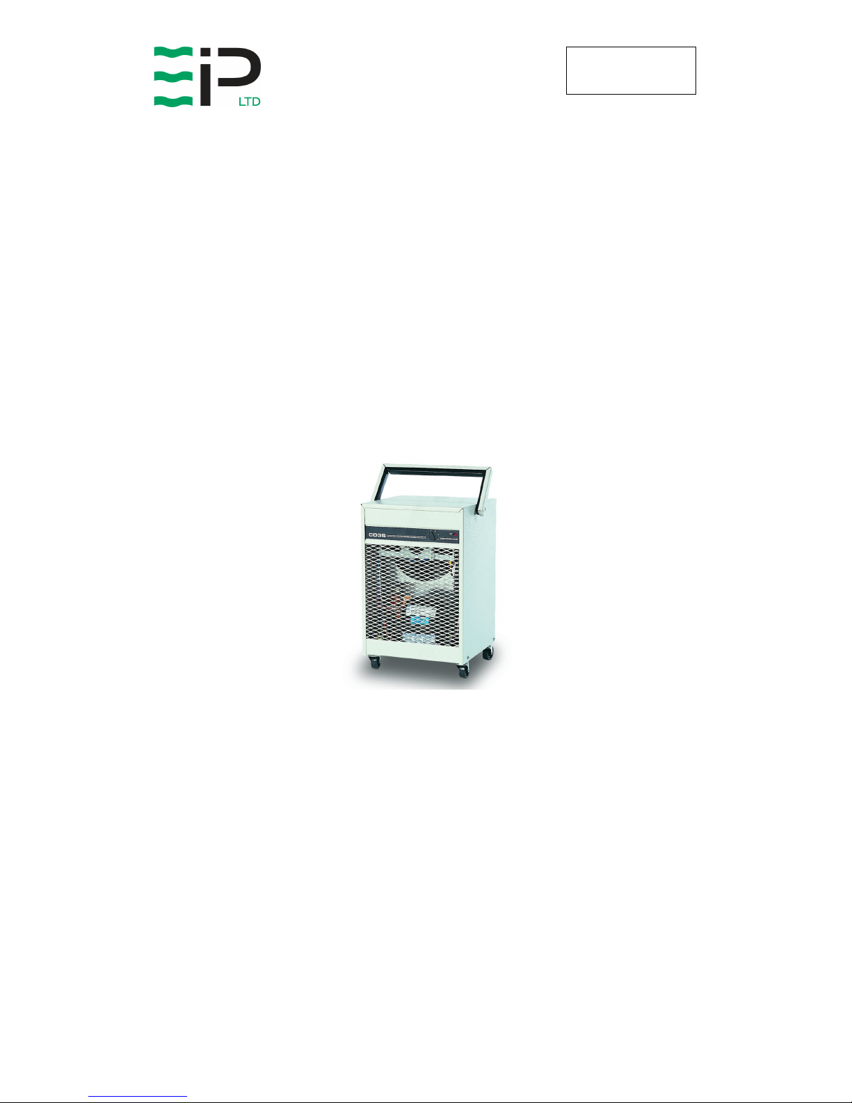
CD35 / CD35P
INDUSTRIAL DEHUMIDIFIER
OWNER’S MANUAL
www.eipl.co.uk
Service Questions: Contact Ebac USA at 1-757 873 6800
Sales Inquiries: Contact Sylvane at (800) 934-9194 or visit sylvane.com
Page 2

Page 2 of 12
Drawing : - TPC225
Issue : - 3
Date : - 05/01/12
INTRODUCTION
Designed for a wide range of applications, the CD35 is a rugged, compact unit
which incorporates its own tank for collected moisture with an automatic
shutoff once the tank is fully. Offices, shops, houses, restaurants and
storerooms can be protected by this simple answer to humidity control.
The CD35 has a number of special features:
•
Adjustable humidistat
•
“Hot Gas” defrost system with solid state controller
•
Whisper-quiet fan
•
Water tank with “full” indicator lamp
•
All galvanized interior
•
Exterior epoxy powder-coated finish
•
Four independent heavy-duty castors
•
Fully enclosed coils
The fan draws the moist air through the cold evaporator coil, which cools the
air below its dew point. Moisture forms on the evaporator coil and is collected
in the condensate tray, which is equipped with a permanent drain. The cooled
air then passes through the hot condenser coil where it is reheated using the
same energy removed during the cooling phase, plus the additional heat
generated by the compressor. The air is, therefore, discharged from the
dehumidifier at a slightly higher temperature with a lower absolute humidity
than that which entered. Continuous circulation of air through the
dehumidifier gradually reduces the relative humidity within the area.
The CD35 dehumidifier is a rugged, reliable drying unit designed to operate
effectively over a broad range of temperature and humidity conditions. An
active hot gas defrost system, controlled by an electronic timer, guarantees
positive de-icing, thereby optimizing operation at low temperatures.
The unit incorporates a welded and galvanized steel chassis and is finished in
an epoxy coating for resilience to damage caused by rough handling.
The CD35 dehumidifier is fitted with an adjustable humidistat to enable you to
select the level of dryness that you desire.
Page 3

Page 3 of 12
Drawing : - TPC225
Issue : - 3
Date : - 05/01/12
SPECIFICATIONS
"This product contains fluorinated greenhouse gases covered by the Kyoto Protocol. The
refrigeration system is hermetically sealed.
The Global Warming Potential (GWP) of refrigerants used in products manufactured by Ebac
Industrial Products Ltd is as follows
R134a – 1300
R407c – 1610
For type and weight of refrigerant contained in this unit, please refer to the product data label"
M
ODEL
: Ebac CD35 / CD35P
H
EIGHT
: 22”
W
IDTH
: 13.5”
D
EPTH
: 14”
W
EIGHT
:
CD35 – 57 lbs
CD35P – 63 lbs
A
IRFLOW
: 170 CFM
P
OWER SUPPLY
: 110V/ 60Hz/ 1 ph
C
URRENT (MAX
):
CD35 – 4 A
CD35P – 5 A
F
AN MOTOR
:
1/50 HP MagneTek
Totally Enclosed
C
OMPRESSOR
:
¼ HP Heavy Duty Fully
Hermetic Tecumseh
C
ONTROL
: Adjustable Humidistat
R
EFRIGERANT
: R-134a
REF. C
HARGE
: 0.17Kg
C
ONSTRUCTION
:
18 AWG Epoxy Power
Coated galvanized
steel
F
EATURES
:
Hot Gas Defrost down
to 33 Deg. F
Page 4

Page 4 of 12
Drawing : - TPC225
Issue : - 3
Date : - 05/01/12
FEATURES
The Adjustable Humidistat: The adjustable humidistat enables you to
maintain the required level of dryness within a room. The humidistat switches
off the CD35 when the relative humidity falls to the level predetermined by the
position of the humidistat control.
The Water Tank: When the water tank has reached its capacity, a float
mechanism will activate a microswitch lever and switch off the machine. The
container-full indicator will also illuminate.
Before emptying the water container, disconnect the power supply and allow
the dryer to stand for five minutes. Remove the container from the rear of the
unit and when emptied, replace, taking care to ensure that the float
mechanism is correctly positioned. Restart unit as instructed in the following
Operation section of this manual.
UNPACKING & INSTALLATION
After removing the CD35 from its shipping container, visually check for signs
of damage. If there is evidence of damage, do not operate. Call your supplier
for advice. Do not discard the packing as it will be useful when transporting
the machine in the future.
Wiring: Connect the power cord to a grounded single phase, 15 Amp fused,
standard household wall socket.
POSITIONING
Single Room: Position the CD35 in the center of the room to be dried.
However, if a damp patch is particularly apparent, the outlet grille should be
directed towards it. If the CD35 cannot be positioned centrally, a minimum
space of 6” should be allowed around the dryer.
Several Rooms: To dry a number of rooms simultaneously with the most
efficiency, the dryer as to be positioned between the rooms. Ensure that all
doors are left ajar allowing a patch for the air to circulate to the unit. An
auxiliary circulation fan would be helpful.
Page 5

Page 5 of 12
Drawing : - TPC225
Issue : - 3
Date : - 05/01/12
SPECIAL FEATURES (where fitted)
CONDENSATE PUMP:
The CD-35 dehumidifier unit can be fitted, either in the factory, or as retro-fit,
with a condensate pump. This condensate pump will allow the unit to run
unattended, with the condensate run off to a permanent drain and can be
used up to 150 feet (50 meters), below the level of a permanent condensate
drainage point.
HUMIDISTAT CONTROL:
The CD-35 dehumidifier unit is fitted with a control humidistat which measures
the relative humidity of the air within the room. The humidistat incorporates a
pointer and scale, which can be adjusted, and set to a relative humidity level
that is acceptable to maintain the required conditions within the room. The
humidistat controls the on/off function of the dehumidifier. When the relative
humidity of the air in the room falls below the set point of the humidistat the
dehumidifier will switch off, but when the relative humidity of the air starts to
rise again and passes the set point the unit will switch on. The humidistat is
used for the on/off function as it is a cost effective method which ensures
power is only used when needed.
TEMPERATURE CONTROLLED DEVICE:
The CD-35 dehumidifier unit is fitted with a temperature sensitive device
which operates in conjunction with the defrost control. In normal operation the
defrost control will come into operation every 45 minutes. This is to ensure
that there will be no build up of ice at lower temperatures. At very low
temperatures it is still possible for the defrost device not to clear the ice
completely from the evaporator coil. To ensure that even at these very low
temperatures all the ice is cleared from the coil, the temperature control
device will stop the fan (preventing air movement). This will increase the
temperature of the evaporator coil even higher, causing all the ice to melt from
the coil during the defrost mode. Where year round conditions need to be
maintained, the dehumidifier unit will have to operate across a wider range of
temperatures. To ensure that the dehumidifier unit operates at its most
efficient, the temperature control device will restrict the defrost operation to
the times when the ambient temperature falls below 25°C.
Page 6

Page 6 of 12
Drawing : - TPC225
Issue : - 3
Date : - 05/01/12
WARNING:
• Due to the high pressures within the refrigeration circuit, under no
circumstances must direct heat be applied to the evaporator coil in an
attempt to remove the build up of ice.
• No attempt should be made to cut open any part of the refrigeration circuit
due to high pressures and gas involved.
•
If the unit is switched off at the mains power supply for any reason, the unit
must be allowed to stand at rest for at least three minutes before
restarting. Failure to do so may cause the unit to blow the fuses owing to
the compressor due to there being a refrigerant imbalance.
Page 7

Page 7 of 12
Drawing : - TPC225
Issue : - 3
Date : - 05/01/12
ROUTINE MAINTENANCE
To ensure continued full efficiency of the dehumidifier, maintenance
procedures should be performed as follows:
Removal of the cover is achieved by means of four screws at the sides of the
unit at base level. With the cover removed all maintenance can be carried out.
1. Clean the surface of the evaporator and condenser coils by blowing
the dirt out from behind the fins with compressed air. Hold the
nozzle of the air hose away from the coil (approx 6”/150 mm) to
avoid damaging the fins. Alternatively, vacuum clean the coils.
2. Check that the fan is firmly secured to the motor shaft and that the
fan rotates freely. Using mobile DD heavy medium oil, lubricate the
motor bearing with 10 drops every 6 months.
3. To check the refrigerant charge, run the unit for 15 minutes and
briefly remove the cover. The evaporator coil should be evenly frost
coated across its surface. At temperatures above 20°C, the coil
may be covered with droplets of water rather than frost. Partial
frosting accompanied by frosting of the thin capillary tubes,
indicates loss of refrigerant gas or low charge.
4. Check all wiring connections.
I
F ANY OF THE PRECEDING PROBLEMS OCCUR, CONTACT THE EBAC
S
ERVICE CENTER PRIOR TO CONTINUED OPERATION OF THE UNIT TO
PREVENT PERMANENT DAMAGE
.
WARNING:
ENSURE THAT THE POWER CORD TO THE MACHINE HAS
BEEN DISCONNECTED BEFORE CARRYING OUT ROUTINE
MAINTENACE ON ITEMS 1, 2, 3, AND 4.
WARNING:
DO NOT STEAM CLEAN REFRIGERATION COILS
Page 8

Page 8 of 12
Drawing : - TPC225
Issue : - 3
Date : - 05/01/12
REPAIRS
1. Should an electrical component fail, consult the Factory Service
Center to obtain the proper replacement part.
2. If refrigerant gas is lost from the machine, it will be necessary to use
a refrigeration technician to correct the fault. Contact the Factory
Service Center prior to initiating this action.
Any competent refrigeration technician will be able to service the
equipment. The following procedure must be used:
a. The source of the leak must be determined and corrected.
b. The machine should be thoroughly evacuated before
recharging.
c. The unit must be recharged with refrigerant measured
accurately by weight.
d. For evacuation and recharging of the machine, use the crimped
and brazed charging stub attached to the side of the refrigerant
compressor.
The charging stub should be crimped and rebrazed after
servicing. N
EVER
allow permanent service valves to be fitted to
any part of the circuit. Service valves may leak causing further
loss of refrigerant gas.
3. The refrigerant compressor fitted to the dehumidifier is a durable
unit that should give many years of service. Compressor failure can
result from the machine losing its refrigerant gas. The compressor
can be replaced by a competent refrigeration technician.
Failure of the compressor can be confirmed by the following
procedure:
a. Establish that power is present at the compressor terminals
using a voltmeter.
b. With the power disconnected, check the continuity of the internal
winding by using meter across the compressor terminals. An
open circuit indicates that the compressor should be replaced.
c. Check that the compressor is not grounded by establishing that
a circuit does not exist between the compressor terminals and
the shell of the compressor.
Page 9

Page 9 of 12
Drawing : - TPC225
Issue : - 3
Date : - 05/01/12
TROUBLESHOOTING
S
YMPTOM
C
AUSE
R
EMEDY
Unit inoperative 1. No power to unit
1. Check the power from
power supply panel
Little or no airflow
1. Loose fan on shaft
2. Fan motor burnt out
3. Dirty refrigeration coils
4. Loose electrical wiring
5. Fuse blown or circuit
breaker tripped
1. Tighten fan
2. Replace the fan motor
3. See Routine Maintenance
Section
4. Check the wiring diagram
to find fault and repair
5. Replace the fuse or reset
the circuit breaker
Little or no water
extraction
1. Insufficient air flow
2. Compressor fault
3. Loss of refrigerant gas
4. Blocked filter dryer
1. Check all of the above
2. Contact the Factory
Service Center
3. Contact the Factory
Service Center
4. Contact the Factory
Service Center
Little or no defrost
when required
1. Faulty timer
2. Faulty by-pass valve
1. Contact the Factory
Service Center
2. Contact the Factory
Service Center
Unit vibrates
excessively
1. Loose compressor
2. Damaged fan
1. Tighten the nuts on the
compressor mounts
2. Replace fan
Water flooding inside
the machine
1. Drain pipe blocked/frozen
2. Drain pipe too high
3. Crimped or blocked tubing
4. Defective Pump
1. Clear the obstruction
2. Ensure that no section of
the drain hose is above the
level of the water outlet
3. Straighten, clear, or replace
tubing
4. Replace pump
Hissing noise from
the machine
1. Machine defrosting –
normal operation
N/A
Page 10

Page 10 of 12
Drawing : - TPC225
Issue : - 3
Date : - 05/01/12
CD35
SPARE PARTS LIST
Part Number
Description
1018611 EVAP COIL ASSY
1137907 WATER CONTAINER
2013865 MICROSWITCH SUPPORT
2013866 MICROSWITCH LEVER
2017707 HUMIDEX 7 KNOB
2131107 HUMIDEX DRAIN TRAY
2131147 CONDENSER COIL
3014272 CAPILLIARY TUBE .031 Already Cut
3020811 BY-PASS VALVE
3020937 FILTER DRYER
3033033 MICROSWITCH
3035145 HUMIDISTAT
3035346 PANEL MOUNTED TERMINAL BLOCK
3036636 RED LAMP ASSY
3040181 FAN BLADE
3050216 CASTOR
1617990 PCB
2141095 MAINS POWER CABLE
3021518 COMPRESSOR BOX COVER
3021543 OHP
3021544 RELAY
3022147 COMPRESSOR
3030421 SOLENOID COIL
3035773 MOTOR
2018641 EVAPORATOR COIL
1600500 PCB (Pre-95 Model)
3030275 110V RELAY (Pre-95 Model)
2013837 DRAIN TRAY
Spare parts available online
www.EIPLDIRECT.com
Page 11

Page 11 of 12
Drawing : - TPC225
Issue : - 3
Date : - 05/01/12
LIMITED WARRANTY
Our products carry a one-year unconditional warranty against any defects in
workmanship or material. This warranty will cover all parts and labour
required to repair your Ebac product. This warranty is invalid if the unit has
been abused, damaged, whether intentional or accidental, or if any
modifications have been made to the unit.
THE FOREGOING WARRANTY IS EXCLUSIVE AND IS ISSUED IN LIEU OF
ALL OTHER WARRANTIES (WHETHER WRITTEN, ORAL, OR IMPLIED)
INCLUDING THE WARRANTY OF MERCHANTABILITY AND THE
WARRANTY OF FITNESS FOR A PARTICULAR PURPOSE. EBAC
INDUSTRIAL PRODUCTS, INC. DISCLAIMS ANY LIABILITY FOR
CONSEQUENTIAL DAMAGES, LOST PROFITS, OR INCIDENTAL
DAMAGES FOR BREACH OF ANY WRITTEN OR IMPLIED WARRANTY
WITH RESPECT TO THE FOREGOING DESCRIBED MERCHANDISE.
For Your Records: Model:____________________
S/N:______________________
Date Received:______________
SAVE THIS SECTION FOR YOUR RECORDS
CLIP AND RETURN THIS CARD
PLEASE NOTE
WARRANTY REGISTRATION
To ensure that your
Ebac Dehumidifier is
accorded the full
coverage provided by
this warranty, please
complete and mail this
card at your earliest
convenience.
Thank You
DATE
MODEL ___________ S/N ________________ RECEIVED ________________
OWNER __________________________________________________________
ADDRESS ________________________________________________________
CITY __________________________ STATE ________ ZIP _______________
COMMENTS ______________________________________________________
_________________________________________________________________
Ebac Industrial Products.
700 Thimble Shoals Boulevard, Suite 109, Newport News, Virginia. 23606-2575
Page 12

Page 12 of 12
Drawing : - TPC225
Issue : - 3
Date : - 05/01/12
UK Head Office
Ebac Industrial Products Ltd
St Helens Trading Estate
Bishop Auckland
County Durham
DL14 9AD
Tel: +44 (0) 1388 664400
Fax: +44 (0) 1388 662590
www.eipl.co.uk
sales@eipl.co.uk
American Sales Office
Ebac Industrial Products Inc
700 Thimble Shoals Blvd.
Suite 109, Newport News
Virginia, 23606-2575
USA
Tel: +01 757 873 6800
Fax: +01 757 873 3632
www.ebacusa.com
sales@ebacusa.com
German Sales Office
Ebac Industrial Products Ltd
Miraustra 64 – 66
13509
Berlin
Germany
Tel: +49 3043 557241
Fax: +49 3043 557240
www.eip-ltd.de
sales@eip-ltd.de
Service Questions: Contact Ebac USA at 1-757 873 6800
Sales Inquiries: Contact Sylvane at (800) 934-9194 or visit sylvane.com
 Loading...