

Eion LibraPlus 5845 User Manual

www.eionwireless.com
LibraPlus 5845
PN: 5724-0003
Document version: 1.74
Released on February 16 2010

This page is intentionally left blank

Table of Contents
1. Important Information ................................................................................................. 1
1.1. Safety Warnings ............................................................................................... 1
1.1.1. Safety Considerations ............................................................................. 1
1.1.2. Warning Symbols Used in this Manual ....................................................... 1
1.2. Notices and Contacts ........................................................................................ 1
1.2.1. Copyright Notice ................................................................................... 1
1.2.2. Regulatory Notice .................................................................................. 2
1.2.3. Other Notices ........................................................................................ 3
1.2.4. Warranty and Repair ............................................................................... 3
1.2.5. Customer Support Contacts ..................................................................... 3
1.2.6. Distributor Technical Support ................................................................... 3
1.2.7. Contact Technical Support ....................................................................... 4
2. Description ................................................................................................................ 5
2.1. LibraPlus Series Products .................................................................................. 5
2.1.1. Overview ............................................................................................. 5
2.1.2. Proprietary Protocol ............................................................................... 5
2.1.3. About OFDM ........................................................................................ 5
2.1.4. About Point-to-Multi-Point (P-MP) Systems ............................................... 6
2.1.4.1. Point to Multipoint based on CSMA ............................................... 7
2.1.4.2. LibraPlus 5845 Adaptive Polling Protocol ........................................ 8
2.1.4.3. Access Point (AP) Equipment ........................................................ 8
2.1.4.4. Customer Premise Equipment (CPE) ............................................... 8
2.1.4.5. Long Range Customer Premise Equipment (LCPE) ........................... 9
2.1.4.6. Radio Operation Background ......................................................... 9
2.1.4.7. Quality of Service (QoS) ............................................................. 10
2.1.5. About Point-to-Point (P-P) Systems ......................................................... 10
2.1.5.1. DenFlow Proprietary Protocol ...................................................... 11
2.1.5.2. Rapid Deployment (RD) Equipment .............................................. 11
2.1.5.3. Extened Range (ER) Equipment ................................................... 11
2.1.6. Hardware ........................................................................................... 11
2.1.7. Specifications ...................................................................................... 16
2.2. System Applications ........................................................................................ 21
2.2.1. Making a Simple Wireless Bridge ........................................................... 21
2.2.2. Creating a Simple Wireless Network ........................................................ 21
3. Field Installation ....................................................................................................... 23
3.1. Introduction ................................................................................................... 23
3.2. LibraPlus Point-to-Point Quick Setup ................................................................. 23
3.2.1. Slave (RD or ER) Unit .......................................................................... 25
3.2.2. Master (RD or ER) Unit ........................................................................ 26
3.3. LibraPlus Point-to-Multipoint Quick Setup .......................................................... 25
3.3.1. CPE Unit ............................................................................................ 25
3.3.2. AP Unit .............................................................................................. 26
3.4. LibraPlus Field Installation ............................................................................... 27
3.4.1. Site Preparation ................................................................................... 27
3.4.2. Tools and equipment ............................................................................. 27
3.4.3. LibraPlus Package Checklist .................................................................. 28
3.4.4. LibraPlus installation procedure .............................................................. 29
3.4.4.1. Mounting the LibraPlus Unit ....................................................... 29
3.4.4.2. Connecting the LibraPlus ............................................................ 30
3.4.4.3. SSH Connection ........................................................................ 30
3.4.4.4. Serial Connection
3.4.4.5. Antenna Alignment .................................................................... 31
3.4.4.6. Configuration and Link Test ........................................................ 32
3.4.4.7. Test network connectivity ............................................................ 32
3.4.4.8. Secure the Installation ................................................................ 33
...................................................................... 30
iii

LibraPlus User Manual
4. Configuration ........................................................................................................... 34
4.1. Getting Started ............................................................................................... 34
4.1.1. LibraPlus Configuration Management ...................................................... 34
4.1.1.1. Configuration types .................................................................... 34
4.1.1.2. Default Login ........................................................................... 34
4.1.1.3. CLI Auto Complete .................................................................... 34
4.1.1.4. CLI Help ................................................................................. 35
4.1.1.5. Viewing Configuration ............................................................... 35
4.1.1.6. Copying Configuration .............................................................. 35
4.1.1.7. Configuration File Format .......................................................... 36
4.1.1.8. Command Summary .................................................................. 37
4.1.2. Running a TFTP server ......................................................................... 38
4.2. Wireless Settings ............................................................................................ 39
4.2.1. Configuring Physical Layer Options ....................................................... 39
4.2.1.1. Setting Radio Mode ................................................................... 39
4.2.1.2. Available Frequencies ................................................................. 39
4.2.1.3. Setting a Specific Carrirer Frequency ............................................ 40
4.2.1.4. Setting Data Transmission Rate .................................................... 41
4.2.2. Configuring SSID ................................................................................ 41
4.2.3. Configuring multiple SSID .................................................................... 41
4.2.4. Advanced Wireless Settings .................................................................... 43
4.2.4.1. Setting Transmit Power ............................................................... 43
4.2.4.2. Setting Distance Parameter .......................................................... 43
4.2.4.3. Setting Dynamic Frequency Selection (DFS) .................................. 44
4.2.4.4. Setting Automatic Transmit Power Control (ATPC) .......................... 44
4.2.5. Wireless Security Settings ...................................................................... 45
4.2.5.1. Wireless Security Overview ......................................................... 45
4.2.5.2. Configuring Wired Equivalent Privacy (WEP) ................................ 47
4.2.5.3. Setting Wi-Fi Protected Access ..................................................... 50
4.2.5.4. Certificate Management ............................................................. 59
4.2.5.5. MAC Address Based Filtering ...................................................... 60
4.2.5.6. Client Bridging ......................................................................... 62
4.2.6. Wireless Interface Monitoring ................................................................ 63
4.2.6.1. Scan Procedure ........................................................................ 63
4.3. MAC Address Settings .................................................................................... 64
4.3.1. MAC Address Setting .......................................................................... 64
4.4. Bridging ....................................................................................................... 64
4.4.1. Configuring transparent bridge ............................................................... 64
4.4.1.1. Creating a bridge ....................................................................... 64
4.4.1.2. Wireless interface configuration ................................................... 65
4.4.1.3. Deleting a bridge ....................................................................... 66
4.4.1.4. Viewing Bridge Status ................................................................ 66
4.4.1.5. Bridge Command Summary ........................................................ 67
4.5. VLAN .......................................................................................................... 68
4.5.1. Overview ............................................................................................ 68
4.5.1.1. Point-to-Point VLAN System ....................................................... 69
4.5.1.2. Point-to-Multipoint VLAN System ............................................... 69
4.5.2. Command Summary ............................................................................. 70
4.6. IP Settings ..................................................................................................... 70
4.6.1. Interface Parameters ............................................................................. 70
4.6.1.1. IP address
................................................................................ 70
4.6.1.2. Dynamic (DHCP) IP address ....................................................... 72
4.6.1.3. IP broadcast address ................................................................... 73
4.6.1.4. MTU size ................................................................................. 73
4.6.2. DNS .................................................................................................. 73
4.6.3. Domain Name ..................................................................................... 74
4.6.4. Host Name .......................................................................................... 75
4.6.5. ARP Table .......................................................................................... 76
iv

LibraPlus User Manual
4.6.6. Static Routing and Default Gateway ........................................................ 77
4.6.7. Static Hosts ......................................................................................... 79
4.7. DHCP Server ................................................................................................. 80
4.7.1. DHCP Server ..................................................................................... 80
4.7.2. Command summary ............................................................................. 82
4.8. Firewall and NAT ........................................................................................... 85
4.8.1. Access Control Lists ............................................................................ 85
4.8.1.1. Source and Destination Specifiers ................................................ 86
4.8.1.2. Access list binding ..................................................................... 86
4.8.1.3. Viewing ACL settings ................................................................. 87
4.8.2. Network Address Translation ................................................................. 88
4.8.2.1. Examples ................................................................................. 89
4.8.2.2. Viewing NAT lists ...................................................................... 89
4.9. PPP .............................................................................................................. 89
4.9.1. Overview ............................................................................................ 89
4.9.2. Command Summary ............................................................................. 91
4.10. RADIUS Profiles .......................................................................................... 95
4.10.1. RADIUS Profiles ............................................................................... 95
4.10.2. Command summary ............................................................................ 96
5. System Maintenance .................................................................................................. 98
5.1. Date and Time ............................................................................................... 98
5.2. NTP ............................................................................................................. 98
5.3. Command Summary ....................................................................................... 99
5.4. System Update ............................................................................................. 102
5.4.1. Overview .......................................................................................... 102
5.4.2. Command Summary ........................................................................... 102
5.5. Reboot ........................................................................................................ 103
5.6. Password Reset ............................................................................................ 104
5.7. SNMP ........................................................................................................ 105
6. Monitoring and Statistics .......................................................................................... 107
6.1. Host Echo Test ............................................................................................. 107
6.2. Packet Capturing .......................................................................................... 107
6.3. Route Tracing .............................................................................................. 108
6.4. System Logging ........................................................................................... 108
6.5. General System Info ...................................................................................... 109
7. Troubleshooting ...................................................................................................... 111
7.1. Troublshooting the LibraPlus .......................................................................... 111
7.1.1. Preventative maintenance ..................................................................... 111
7.1.2. Troubleshooting Areas ......................................................................... 111
7.1.3. Troubleshooting Chart ......................................................................... 113
8. Appendices ............................................................................................................ 117
8.1. Appendix A: Glossary .................................................................................... 117
8.2. LibraPlus 5845 Integrated Antenna Specifications ............................................... 125
v

List of Figures
2.1. Orthogonal Arrangement of OFDM Subchannels ............................................................ 7
2.2. LibraPlus P-MP System Components ........................................................................... 7
2.3. Time Division Duplexing Channels ............................................................................ 10
2.4. Time Division Multiplexing/Time Division Multiple Access (TDM/TDMA) ...................... 10
2.5. LibraPlus Connection Panel ...................................................................................... 12
2.6. CAT-5 Weatherproofing Kit ...................................................................................... 12
2.7. Round Cable Bead .................................................................................................. 12
2.8. LibraPlus AP, ER and LCPE Front Panel RF Connector ................................................. 13
2.9. Ethernet Power Inserter ............................................................................................ 13
2.10. Mounting ............................................................................................................ 14
2.11. Large Pipe Diameter Mounting Configuration ............................................................ 14
2.12. Small Pipe Diameter Mounting Configuration ............................................................ 15
2.13. Wall Mounting Configuration .................................................................................. 15
2.14. Point-to-Point Wireless Bridge ................................................................................ 29
2.15. Point-to-Multipoint Wireless Network ....................................................................... 29
3.1. Installation Process ................................................................................................. 23
3.2. LibraPlus Assembly Diagram .................................................................................... 29
3.3. COM 1 Propertries .................................................................................................. 31
4.1. Multipoint VLAN Configuration ............................................................................... 69
8.1. Azimuth Radiation Pattern Midband Freq. 5.45 GHz ................................................... 129
8.2. Azimuth Radiation Pattern Midband Freq. 5.35 GHz ................................................... 129
vi

List of Tables
2.1. LibraPlus 5845 Radio Specifications .......................................................................... 17
2.2. LibraPlus 5845 Network Support Specifications ......................................................... 114
2.3. LibraPlus 5845 Wireless Networking Specifications .................................................... 114
2.4. LibraPlus 5845 Security Specifications ..................................................................... 114
2.5. LibraPlus 5845 Management Specifications ............................................................... 114
2.6. LibraPlus 5845 Physical, Electrical and Environmental Specifications ............................. 114
4.1. WPA Configuration Table ........................................................................................ 52
4.2. Source and Destination Specifiers .............................................................................. 86
5.1. NTP client parameters ............................................................................................. 99
7.1. Troubleshooting Chart ........................................................................................... 114
8.1. Integrated Antenna Specifications - Electrical ............................................................. 126
8.2. Integrated Antenna Specifications - Mechanical .......................................................... 127
8.3. Integrated Antenna Specifications - Envorinmental ...................................................... 128
vii

List of Examples
4.1. Viewing configuration ............................................................................................. 35
4.2. Viewing configuration part ....................................................................................... 35
4.3. Configuration backup and restore .............................................................................. 36
4.4. Specify IEEE 802.11 mode ....................................................................................... 39
4.5. List supported channels ........................................................................................... 40
4.6. Set Carrier Frequency .............................................................................................. 40
4.7. Set data rate ........................................................................................................... 41
4.8. Specify Service Set ................................................................................................. 41
4.9. Configuring Multiple SSID ...................................................................................... 42
4.10. Setting Transmit Power .......................................................................................... 43
4.11. Setting the Distance Parameter ................................................................................ 44
4.12. Enable DFS ......................................................................................................... 45
4.13. Enable DFS ......................................................................................................... 45
4.14. Static WEP access point ......................................................................................... 48
4.15. Static WEP EAP-MD5 station (CPE) ........................................................................ 48
4.16. Dynamic WEP TTLS station (CPE) .......................................................................... 49
4.17. Set/Delete WEP key by index .................................................................................. 50
4.18. Access point WPA+WPA2 PSK example ................................................................... 50
4.19. Access point WPA+WPA2 EAP example ................................................................... 51
4.20. WPA2 PSK station (CPE) ....................................................................................... 52
4.21. WPA PEAP station (CPE) ....................................................................................... 53
4.22. WPA2 EAP-TLS station (CPE) ................................................................................ 53
4.23. WPA2 EAP-TTLS+MD5 station (CPE) ..................................................................... 54
4.24. Download a PEM file from a TFTP server ................................................................. 60
4.25. Show Certificate Contents ...................................................................................... 60
4.26. Add/Delete MAC address to list ............................................................................... 61
4.27. Add/Delete MAC address using short command form .................................................. 61
4.28. MAC Address White/Black list ................................................................................ 62
4.29. Disconnect remote station ....................................................................................... 62
4.30. Enable client bridging between CPEs ........................................................................ 63
4.31. Interface Scan. ..................................................................................................... 63
4.32. Set an interface MAC Address ................................................................................. 64
4.33. Enable WDS Mode ............................................................................................... 66
4.34. Deleting a Bridge .................................................................................................. 66
4.35. Add Interface to Bridge Group ................................................................................. 67
4.36. Assign a bridge IP legatee ....................................................................................... 67
4.37. View Members of Bridge Group .............................................................................. 68
4.38. View MAC Address of a Bridge Interface .................................................................. 68
4.39. Bridging a wireless VLAN to an untagged wired link ................................................... 70
4.40. Setting an IP address ............................................................................................. 71
4.41. Adding secondary IP addresses ................................................................................ 71
4.42. Deleting an IP address ........................................................................................... 72
4.43. Deleting all IP addresses ........................................................................................ 72
4.44. Add/Remove DNS Server ....................................................................................... 74
4.45. View the name server list contents ............................................................................ 74
4.46. Set/Clear local domain name ................................................................................... 75
4.47. View local domain name setting ............................................................................... 75
4.48. Set/Clear local host name ....................................................................................... 75
4.49. View local host name setting ................................................................................... 76
4.50. Creating and Deleting an ARP Record ...................................................................... 76
4.51. Create ARP Table
4.52. View ARP Cache .................................................................................................. 77
4.53. Show ARP Cache Size ........................................................................................... 77
4.54. Add static route .................................................................................................... 78
4.55. Delete static route ................................................................................................. 78
................................................................................................. 77
viii

LibraPlus User Manual
4.56. Show static route .................................................................................................. 79
4.57. Add/Delete host table entry ..................................................................................... 79
4.58. View static host table ............................................................................................. 80
4.59. Network pool configuration .................................................................................... 81
4.60. Host pool configuration .......................................................................................... 82
4.61. Set and Disable Pool Type ...................................................................................... 82
4.62. Set pool type to host .............................................................................................. 83
4.63. Add DHCP client address range to a network pool ....................................................... 83
4.64. Set DHCP Lease Time ........................................................................................... 84
4.65. Set default gateway IP addresses for DHCP clients ...................................................... 84
4.66. Set DNS server IP addresses for DHCP clients ........................................................... 85
4.67. Set a MAC address for a host pool ............................................................................ 85
4.68. Deny everything ................................................................................................... 86
4.69. Permit TCP .......................................................................................................... 87
4.70. Permit TCP for a subnetwork .................................................................................. 87
4.71. Open various TCP and UDP ports ............................................................................ 87
4.72. Viewing ACL ....................................................................................................... 88
4.73. Simple NAT ......................................................................................................... 89
4.74. Masquerade ......................................................................................................... 89
4.75. Port forwarding .................................................................................................... 89
4.76. PPTP interface ..................................................................................................... 90
4.77. PPPoE interface .................................................................................................... 91
4.78. Set PPP interface name .......................................................................................... 92
4.79. Set PPP authentication identity ................................................................................ 92
4.80. Set/Clear PPP authentication password ...................................................................... 93
4.81. Enable/Disable PPP autoconnection ......................................................................... 93
4.82. Enable/Disable MPPE encryption ............................................................................ 93
4.83. Enable/Disable PAP authentication ........................................................................... 94
4.84. Enable/Disable CHAP authentication ........................................................................ 94
4.85. Enable/Disable MSCHAP authentication ................................................................... 94
4.86. Enable/Disable MSCHAPv2 authentication ............................................................... 95
4.87. Enable/Disable setting defualt gateway ..................................................................... 95
4.88. Accept/Ignore remote DNS ..................................................................................... 95
4.89. RADUIS profile settings ........................................................................................ 97
5.1. Set System Date and Time ........................................................................................ 98
5.2. NTP client configuration .......................................................................................... 99
5.3. Start/Stop NTP client service .................................................................................. 100
5.4. Add/Remove NTP server ........................................................................................ 100
5.5. Set NTP Retry count .............................................................................................. 100
5.6. Set NTP retry period .............................................................................................. 101
5.7. Set a time period between successive clock synchronizations ......................................... 101
5.8. Set NTP timeout ................................................................................................... 101
5.9. Set NTP offset ...................................................................................................... 102
5.10. Firmware update ................................................................................................. 102
5.11. Download firmware image .................................................................................... 103
5.12. System update .................................................................................................... 103
5.13. Reboot .............................................................................................................. 104
5.14. Show reboot timer ............................................................................................... 104
5.15. Change Password ................................................................................................ 104
5.16. Set SNMP Community ......................................................................................... 105
5.17. Set SNMP Contact
.............................................................................................. 105
5.18. Set SNMP Location ............................................................................................. 105
5.19. Set SNMP Allow ................................................................................................. 106
5.20. Enable/Disable SNMP Agent ................................................................................. 106
6.1. Ping a host ........................................................................................................... 107
6.2. Capture TCP packets ............................................................................................. 108
6.3. Traceroute. .......................................................................................................... 108
6.4. Start syslog service ................................................................................................ 109
ix

LibraPlus User Manual
6.5. Show CPU load .................................................................................................... 109
6.6. Show uptime ........................................................................................................ 109
6.7. Show interfaces .................................................................................................... 110
x

Chapter 1. Important Information
1.1. Safety Warnings
1.1.1. Safety Considerations
This document must be reviewed for familiarization with the product, instructions, and safety symbols
before operation.
Verify that local safety regulations are adhered to during installation with regard to grounding and
lightning protection.
Verify that the correct AC power source is available for the Power Inserter.
Disconnect the product from operating power before cleaning.
1.1.2. Warning Symbols Used in this Manual
Warning
Injury or death may result from failure to heed a WARNING. Do not proceed beyond a
WARNING until the indicated conditions are fully understood and met.
Caution
Damage to equipment may result from failure to heed a caution. Do not proceed beyond a
CAUTION until the indicated conditions are understood and met.
Important
Indicates critical information to be aware of which may affect the completion of a task or
successful operation of equipment.
Warning
All antennas must be installed by a knowledgeable and professional installer.
Caution
An antenna must be connected to the AP, LCPE or ER unit before powering up the equipment.
Powering up equipment without an antenna connected can permanently damage the unit or
the RF transmission cable
Caution
Change the passwords and community names as soon as possible. Default community names
and passwords given in this book are provided to all customers and are not secure.
1.2. Notices and Contacts
1.2.1. Copyright Notice
Copyright © July 2009 EION, Inc.
All rights reserved.
1

Important Information
This guide, the application and hardware described herein are furnished under license and are subject
to a confidentiality agreement. The software and hardware can be used only in accordance with the
terms and conditions of this agreement.
No part of this guide may be reproduced or transmitted in any form or by any means – electronic,
mechanical, or otherwise, including photocopying and recording – without the express written permission
of EION, Inc.
While every effort has been made to ensure that the information contained in this guide is correct,
EION, Inc. does not warrant the information is free of errors or omissions. Information contained in
this guide is subject to change without notice.
1.2.2. Regulatory Notice
The specifications and parameters of the device described in this document are subject to change
without notice.
The LibraPlus 5845 product presented in this guide complies with the following regulations and/or
regulatory bodies.
• IC RSS-210 ISS-03 of Industry Canada
• IC: 8367A-5845001
• IC: 6545A-XR5 Modular Approval
• FCC Part 15.247, subpart C, 15.203, 15.207 (2007), 15.109, 15.407
• ETSI EN 301 489-1, EN 301 893, EN 301 489-17 (EMC Wideband data and HIPERLAN)
• ETSI EN 50385-2002, EN 55022, EN 61000
• Safety: UL 60950 equivalent EN60950 (EU); Modular approvals (electrical)
Operation is subject to the following two conditions.
• This device may not cause interference
• This device must accept any interference, including interference that may cause undesired operation
of the device
For Canadian regulatory information, go to www.ic.gc.ca. For American regulatory information, see
www.fcc.gov. For European regulatory information, see www.etsi.org.
This equipment generates, uses and radiates energy on radio frequencies and, if not installed and used
in accordance with this guide, may cause harmful interference to radio communications. However,
there is no guarantee that interference will not occur in a particular installation.
If this equipment does cause harmful interference to radio or television reception, which can be determined by turning the equipment off and on, the user is encouraged to correct the interference by one or
more of the following methods:
• reorient or relocate the receiving antenna
• move the equipment and receiver farther apart
• connect equipment to an outlet on a circuit different from that to which the receiver is connected
This equipment has been tested and found to comply with the limits for a Class B digital device, pursuant to part 15 of the FCC Rules. These limits are designed to provide reasonable protection against
harmful interference in a residential installation. This equipment generates, uses and can radiate radio
2

frequency energy and, if not installed and used in accordance with the instructions, may cause harmful
interference to radio communications. However, there is no guarantee that interference will not occur
in a particular installation. If this equipment does cause harmful interference to radio or television reception, which can be determined by turning the equipment off and on, the user is encouraged to try
to correct the interference by one or more of the following measures:
• Reorient or relocate the receiving antenna.
• Increase the separation between the equipment and receiver.
• Connect the equipment into an outlet on a circuit different from that to which the receiver is connected.
• Consult the dealer or an experienced radio/TV technician for help.
1.2.3. Other Notices
Changes or modifications to the equipment not expressly approved by EION, Inc., could void the
user’s authority to operate the equipment.
Appropriately shielded remote I/O serial cable with the metal connector shell and cable shield properly
connected to chassis ground shall be used to reduce the radio frequency interference.
Important Information
All antenna installation work shall be carried out by a knowledgeable and professional installer.
The parts in some LibraPlus versions are Imperial sizes – inches and fractions of a inch. Do not attempt
to mix Imperial nuts, bolts and screws with similar metric hardware. This will strip the threads.
1.2.4. Warranty and Repair
Please contact the party from whom you purchased the product for warranty and repair information.
EION provides no direct warranty to end users of this product.
1.2.5. Customer Support Contacts
Users of EION equipment who require technical assistance must contact their reseller or distributor.
For information on distributors in your area, please visit www.eionwireless.com/partners.
1.2.6. Distributor Technical Support
Distributors may contact EION’s Technical Support on EION’s products. When requesting support,
please have the following information available;
• configuration of the system, including models of EION equipment, versions and serial numbers
• antenna type and cable lengths
• site information, including possible RF path problems, such as trees, buildings and other RF equipment in the area
• distance of the RF link
• configuration of unit.
• description of the problem
3

Important Information
1.2.7. Contact Technical Support
By Telephone Call: 1-613-271-4400
Business hours: 8:00 a.m. to 5:00 p.m. Eastern Standard Time (GMT - 5)
Online request form at www.eionwireless.com/support
To obtain information regarding EION products, contact the EION distributor in your region, or call
1-613-271-4400 to speak with a EION sales representative or visit our web site at www.eionwireless.com.
4

Chapter 2. Description
2.1. LibraPlus Series Products
2.1.1. Overview
The information in this guide applies to the EION "LibraPlus" series products. This chapter presents
an overview of the features and different models in the LibraPlus Series product family.
2.1.2. Proprietary Protocol
The LibraPlus uses proprietary protocols to acheive performance metrics that far exceed those offered
by traditional WiFi devices. In a point-to-multipoint network, the LibraPlus 5845 employs a proprietary
Adaptive Polling protocol to ensure an optimum distribution of bandwith to clients. In a Point-to-Point
deployment, the Denflow protocol enables the creation of a highly-secure, high-throughput wireless
link. Additional information on these proprietary protocols is located in the folowing sections of this
manual.
2.1.3. About OFDM
The LibraPlus system uses Orthogonal Frequency Division Multiplexing (OFDM) technology to process,
transmit and receive data in parallel fashion over the air. OFDM divides a wide RF frequency band
into several subchannels that work together to deliver data, similar to splitting a road into several lanes
that together can handle more traffic than a single lane.
OFDM offers many advantages, including effective use of bandwidth, resistance to interference, ability
to take advantage of multipath characteristics, and advanced error correction and recovery. Because
data is spread across all the channels, interference usually affects only a few channels rather than all
channels, and lost data can be easily recovered. Since OFDM is insensitive to interference, the amount
of ongoing tuning, adjustment and maintenance is minimized. Both multipoint networks and point-topoint backbone systems are supported.
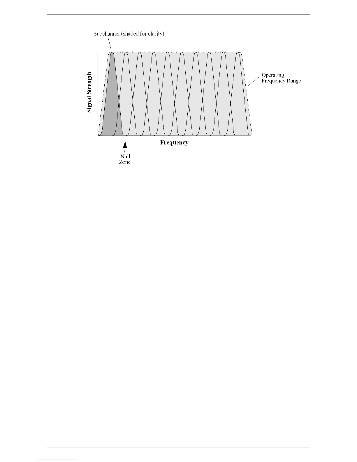
The following diagram illustrates the main concept behind OFDM. The available frequency spectrum
is divided into subchannels. Each subchannel is orthogonal, meaning that the peak signal strength of
each signal occurs at the null or point of minimum signal strength of its neighbor, so adjacent
subchannels do not interfere with each other. Data is carried in parallel across the subchannels.
5
Description
Fig. 2.1. Orthogonal Arrangement of OFDM Subchannels
2.1.4. About Point-to-Multi-Point (P-MP) Systems
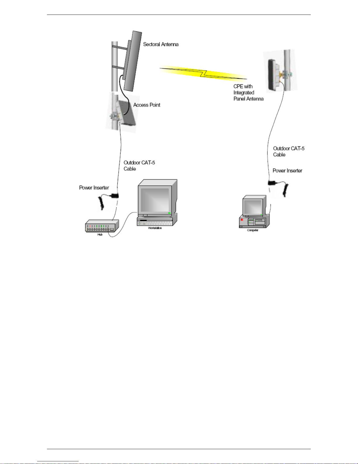
Two kinds of equipment are required for a wireless P-MP link: Access Point (AP) equipment and
Customer Premise Equipment (CPE). AP equipment is located at the service provider’s site and CPE
equipment is located at the customer’s site. The LibraPlus P-MP product is available as an AP, a CPE
with integrated 23 dBi antenna or an LCPE for connection to higher gain external antennas.
6
Description
Fig. 2.2. LibraPlus P-MP System Components
2.1.4.1. Point to Multipoint based on CSMA
A CSMA/CA (Carrier Sense Multiple Access With Collision Avoidance) system will require that all
remote stations be able to hear one another. If any one station in the system cannot hear all the rest of
the stations, collisions will most likely occur. A CSMA station will first listen to the air, if it hears no
other station transmitting, then it will start transmitting. If a CSMA station hears another station's signal
it waits until the transmission halts. If any one station is "out of range" of another station it is quite
possible for them both to attempt to transmit at the same time, resulting in collisions.
The CSMA/CA protocol has severe limitations in many multipoint applications. The biggest problems
arise when the data traffic load is high; that is, when every station has a lot of data to send at the same
time. This can lead to every station being in Collision Avoidance mode and the link is unlikely to be
optimally utilized.
CSMA/CA does not share the available bandwidth fairly; a site with a strong signal has a great advantage
over a site with a weak signal. This is termed "capture effect" and results in one site gaining more
share of the available bandwidth during transmission. Finally, CSMA/CA bridging devices also experience problems when some sites in a network are not within listening distance of some other sites on
the network. This can lead to two or more sites attempting to transmit at the same time, resulting in
transmission collisions.
7

Description
2.1.4.2. LibraPlus 5845 Adaptive Polling Protocol
The LibraPlus solves all the issues related to CSMA/CA by using a Proprietary Adaptive Polling RF
protocol that provides Media Access Control (MAC) for the Access Point and the remote users to appropriately share the RF channel.
The Adaptive Polling Proprietary Protocol is a polling-based protocol. In brief, the Access Point performs a central control on the RF channel by polling the remote users (subscribers) in a round-robin
fashion. If the polled user has data to send, then it immediately sends the data to the base station; otherwise, it keeps silent, in which case the base station will timeout and then starts to poll the next user.
Remotes need not have a communication path between them. With this adaptive polling action occurring,
each station gets their opportunity to transmit data to the master station. This is done in a sequential
format, first remote station#1, then #2, then #3 etc. When all remotes have been given their opportunity
to communicate, the process repeats itself, again and again.
The LibraPlus 5845 uses intelligence to determine the number of polling cycles every user gets depending on the level of its activity. This way the network resources are not wasted during the polling of
inactive users due to no user data transmission. A mechanism is also provided for an inactive user to
become active and to resume its data transmission. The variation of polling cycles also has the potential
support greater total number of CPEs.
2.1.4.3. Access Point (AP) Equipment
The AP controls communication within the wireless network and is the main access point to the Ethernet.
The access point communicates with the CPE’s in the system to provide each CPE with Access to the
main network (i.e. Ethernet). The access point is typically located at a distance away from the CPE
that will provide adequate radio signal strength for the specified data rates.
The Access Point is responsible for any CPE data management functions.
The LibraPlus AP consists of three parts: 1) AP radio unit, 2) Ethernet Power Inserter with CAT-5
cable (bought separately) and weatherproofing kit (included), and 3) the External Antenna and cable
(both bought separately).
• LibraPlus AP. The AP is the main piece of radio equipment. It is designed for outdoor installation
but can also be installed indoors if needed. The AP is equipped with an N-type (F) RF connector so
that the external antenna can be connected to it. Thus many different types of base stations can be
deployed using sectoral, omni or other specialized antennas.
• Ethernet Power Inserter. This piece of equipment is a small box that connects between the
CPE and the P.C. This box also provides power for the AP equipment to run. A CAT-5 outdoor
cable is used to connect the Power inserter to the AP. The weatherproofing kit is used with standard
RJ-45 connector to ensure reliable connection for outdoor systems.
• Antenna and Cable. In order to accommodate different frequency re-use plans and scalability
of the base stations the AP is designed to be used with an external antenna. Antennas and cables are
selected by the user based on the network requirements.
2.1.4.4. Customer Premise Equipment (CPE)
The CPE equipment connects customers to the AP via a wireless link. The link enables customers to
communicate with other users of the wireless network and the Ethernet. Customer Premise Equipment
has two parts: 1) CPE radio unit and 2) Ethernet Power Inserter with CAT-5 cable (bought separately)
and weatherproofing kit (included).
8

Description
• LibraPlus CPE. The CPE is the main piece of equipment that would normally be installed out-
doors (indoor installation is permitted when feasible) The CPE contains all of the necessary radio
equipment to provide a high-speed wireless link. The CPE also has an integral antenna such that no
RF cables are required for a typical installation.
• Ethernet Power Inserter. This piece of equipment is a small box that connects between the
CPE and the P.C. This box also provides power for the CPE equipment to run. A CAT-5 outdoor
cable is used to connect the Power Inserter to the CPE. The weatherproofing kit is used with standard
RJ-45 connector to ensure reliable connection for outdoor systems.
Wireless network activity focuses on the AP, which is both the main access point to the Ethernet (LAN
or WAN) and the destination for CPE-originated communications (CPEs do not communicate directly
with other CPEs—they communicate only via the AP). CPEs complete the customer-end of a wireless
link.
2.1.4.5. Long Range Customer Premise Equipment (LCPE)
The LCPE equipment also connects customers to the AP via a wireless link. The LCPE enables the
customer to reach longer ranges by allowing the connection to a higher gain external antenna. It can
also be used for indoor installation of the units should severe weather conditions require it. The antenna
is then mounted outdoors and connected via appropriate RF cables to the unit. One other alternative
which customers may want to consider is to use lower gain antennas with systems that are very close
to the Base Station to mitigate some interference concerns without recourse to dynamic power control.
The LibraPlus LCPE consists of three parts: 1) LCPE, 2) Ethernet Power Inserter with CAT-5 cable
(bought separately) and weatherproofing kit (included), and 3) the External Antenna and cable (both
bought separately).
• LibraPlus LCPE. The LCPE is the main piece of equipment. It is designed for outdoor installation
but can also be installed indoors if needed. The LCPE is equipped with an N-type connector so that
the external antenna can be connected to it. Thus the range of the P-MP system can be significantly
increased by use of higher gain antennas. Also, in situations where very severe conditions may be
encountered outdoors the LCPE can be installed indoors with cabling to the antenna outside.
• Ethernet Power Inserter. This piece of equipment is a small box that connects between the
LCPE and the P.C. This box also provides power for the LCPE equipment to run. A CAT-5 outdoor
cable is used to connect the Power inserter to the LCPE. The weatherproofing kit is used with
standard RJ-45 connector to ensure reliable connection for outdoor systems.
• Antenna and Cable. In order to accomodate different range requirements for P-MP links, the
LCPE is designed to be used with an external antenna. Antennas and cables are selected by the user
based on the network requirements.
2.1.4.6. Radio Operation Background
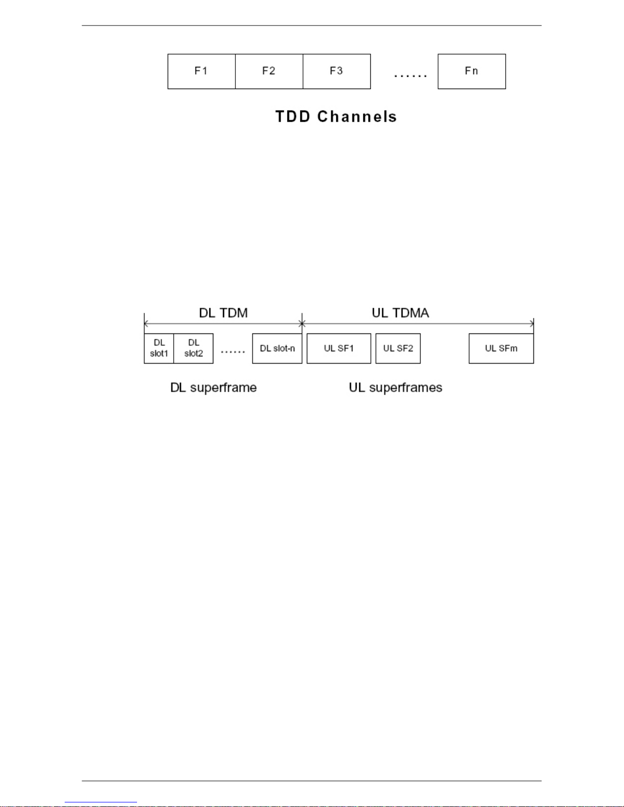
The LibraPlus communicates using a technique call Time Division Duplexing (TDD) in both the P-P
and P-MP configurations. TDD uses one frequency for both the Down Link (DL) Transmission (Base
to Remote in P-P, or AP to CPEs in P-MP), and for the Up Link (UL) (Remote to Base in PP or CPEs
to AP in P-MP). The DL and UL transmissions are performed at different times, therefore the system
is known as a Time Division Duplexing system. The available frequency band is therefore separated
into multiple TDD channels allowing for use of the whole frequency bands for very high capacity.
9
Description
Fig. 2.3. Time Division Duplexing Channels
In addition to using TDD, in a P-MP system, the AP and CPE also use Time Division Multiplexing
(TDM). TDM is a process of using time slots to allow the AP to transmit to multiple CPEs during a
single transmit cycle. During the Up Link cycle each CPE is polled and if it has data it transmits in
turn. This is known as Time Division Multiple Access (TDMA). All CPEs thus share the bandwidth
available by allocating time slots in turn to each of the units on both transmit and receive channels.
The following diagram shows TDM in a DL and TDMA in the UL. Each slot is allocated to a different
CPE. In the EION system each slot may vary in time depending on traffic destined for each of the
CPEs. CPEs that are not very active will also be polled less frequently thus reducing the latency of the
system. Once they are ready to transmit or receive they will move up the polling list and will be polled
more often.
Fig. 2.4. Time Division Multiplexing/Time Division Multiple Access (TDM/TDMA)
Antenna characteristics and placement are critical. Because of OFDM’s excellent Non-Line of Sight
performance and its resistance to frequency selective multipath fading CPE directional antennas do
not have to be pointed directly at the AP antenna. Having a clear line of sight is always preferable, but
is not necessary with the LibraPlus series. There are cases in which the optimal performance is achieved
when the CPE antenna does not point directly to the AP (e.g. when using reflection off a nearby
structure to avoid an absorbing obstruction).
2.1.4.7. Quality of Service (QoS)
In the LibraPlus 5845 Quality of Service QoS is achieved through the provisioning of the WMM
(Wireless MultiMedia Extensions). WMM prioritizes traffic according to four Access Categories (AC)
- voice, video, best effort, and background. WMM creates QoS for traffic priority management to time-
sensitive applications such as voice, video and multimedia traffic. A WMM QoS scheme can be further
enhanced through the use of VLAN customer separation.
2.1.5. About Point-to-Point (P-P) Systems
For P-P systems LibraPlus comes in two versions, the Rapid Deployment (RD) and the Extended
Range (ER) units. P-P links are used when only two locations are connected, for example for backhaul
purposes between P-MP Base Stations and the Network Operating Center for connection to the Internet
backbone, or in situations where throughput requirements between two locations are such that the
bandwidth can’t be shared.
10

Description
2.1.5.1. DenFlow Proprietary Protocol
DenFlow is a proprietary protocol that enhances LibraPlus 5845 performance and security for radios
in a Point-to-Point configuration. With DenFlow, the radios will dynamically report and optimize the
productivity of channels for PTP communication. The Denflow protocol improves system performance
and work to protect the link against interference.
2.1.5.2. Rapid Deployment (RD) Equipment
The RD equipment is intended for very rapid installation of a P-P link and can be used for links of up
to 25 kms (up to 3 kms at full 45 Mbps actual bandwidth). RD Equipment has two parts: 1) RD and
2) Ethernet Power Inserter with CAT-5 cable (bought separately) and weatherproofing kit (included).
• LibraPlus RD. The RD is the main piece of equipment that is normally installed outdoors (indoor
installation is permitted when the range and link budget allows it). The RD contains all of the necessary radio equipment to provide a high-speed wireless link. The RD also has an integral 23 dBi antenna such that no RF cables are required for a typical installation.
• Ethernet Power Inserter. This piece of equipment is a small box that connects between the RD
and the Ethernet network. This box also provides power for the RD equipment to run. A CAT-5
outdoor cable is used to connect the Power inserter to the RD. The weatherproofing kit is used with
standard RJ-45 connector to ensure reliable connection for outdoor systems.
2.1.5.3. Extened Range (ER) Equipment
The ER Equipment allows for the use of different external antennas to achieve links of much longer
range (up to 50 kms). It can also be used for indoor installation of the units should severe weather
conditions require it. The antenna is then mounted outdoors and connected via appropriate RF cables
to the unit.
The LibraPlus ER consists of three parts: 1) ER, 2) Ethernet Power Inserter with CAT-5 cable (bought
separately) and weatherproofing kit (included), and 3) the External Antenna and cable (both bought
separately).
• LibraPlus ER. The ER is the main piece of equipment. It is designed for outdoor installation
but can also be installed indoors if needed. The ER is equipped with an N-type connector so that
the external antenna can be connected to it. Thus the range of the P-P system can be significantly
increased by use of higher gain antennas. Also, in situations where very severe conditions may be
encountered outdoors the ER can be installed indoors with cabling to the antenna outside.
• Ethernet Power Inserter. This piece of equipment is a small box that connects between the ER
and the Ethernet network. This box also provides power for the ER equipment to run. A CAT-5
outdoor cable is used to connect the Power inserter to the ER. The weatherproofing kit is used with
standard RJ-45 connector to ensure reliable connection for outdoor systems.
• Antenna and Cable. In order to accommodate different range requirements for P-P links, the
ER is designed to be used with an external antenna. Antennas and cables are selected by the user
based on the network requirements.
2.1.6. Hardware
This section describes the LibraPlus hardware. Although antennas are part of the equipment in general,
antennas are not discussed here. The LibraPlus product has one connector Power/Ethernet Port on the
back panel common for all types of LibraPlus equipment. The AP, ER and LCPE units also have a
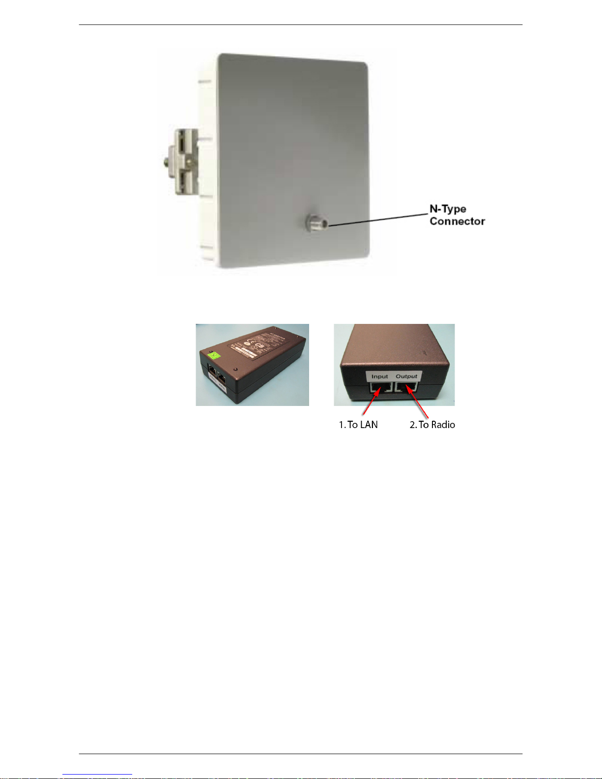
female N-Type connector on the front panel for connection to the antenna.
11
Description
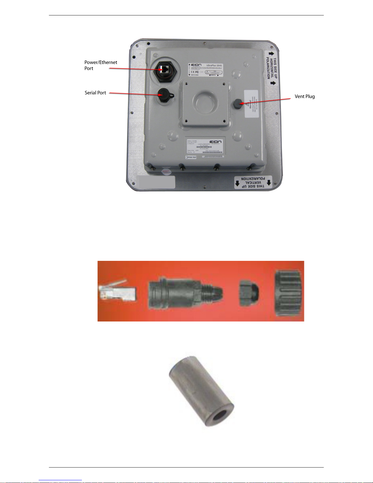
Fig. 2.5. LibraPlus Connection Panel
1. Power/Ethernet Port. Standard RJ 45 Ethernet Connector. A weatherproofing kit is provided
with the unit, so that standard outdoor CAT-5 cable can be used.
2. Serial Port. 5-pin female connector. A matching connector and cable is available separately for
local configuration.
Fig. 2.6. CAT-5 Weatherproofing Kit
Fig. 2.7. Round Cable Bead
12
Description
Fig. 2.8. LibraPlus AP, ER and LCPE Front Panel RF Connector
Fig. 2.9. Ethernet Power Inserter
1. To Ethernet LAN
2. To LibraPlus Radio
Caution
Before connecting the LibraPlus to a power source, ensure that you are using the correct
power supply for your radio. LibraPlus radios with a mfg rls number prior to B0 require a
different power supply. Contact your distributor for details.
13
Description
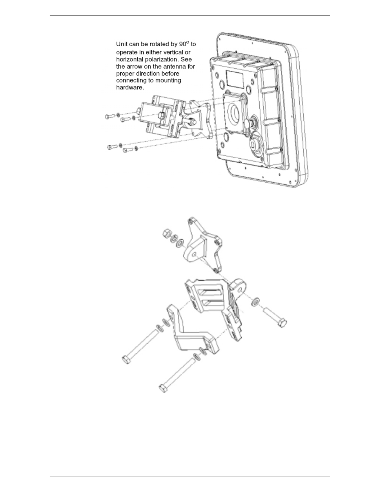
Fig. 2.10. Mounting
Fig. 2.11. Large Pipe Diameter Mounting Configuration
14
Description
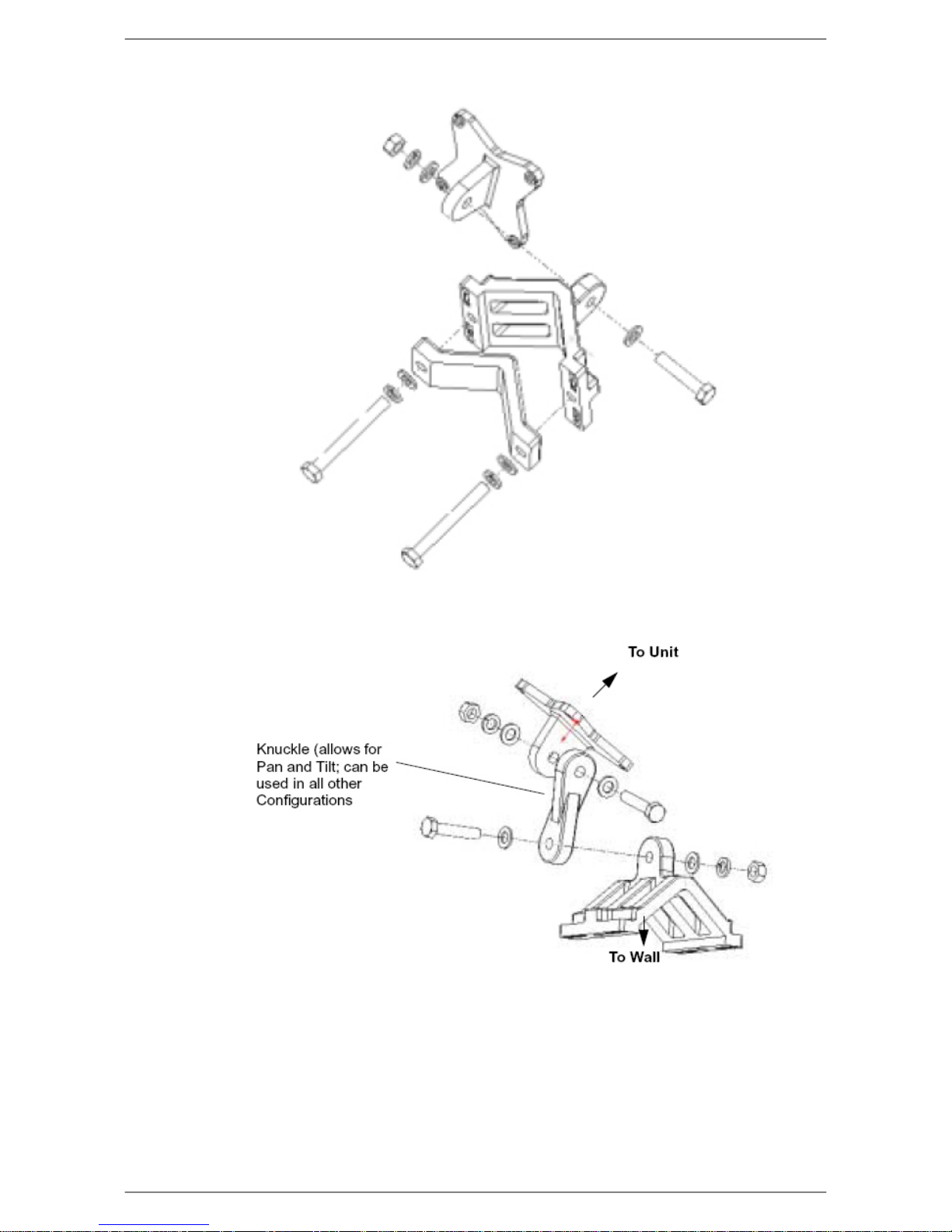
Fig. 2.12. Small Pipe Diameter Mounting Configuration
Fig. 2.13. Wall Mounting Configuration
15

2.1.7. Specifications
Description
16

Radio Specifications
Topology
Coverage/Range
Frequency
Channel Size
Description
RD, ER: Point-to-Point (PtP)
AP, CPE, LCPE: Point-to-Multipoint (PtMP)
AP: up to 20 km (12 miles) with 36 dBi antenna on CPE side
CPE: up to 5 km (3 miles)
ER: up to 50 km (30 miles) with 36 dBi antenna
RD: up to 10 km (6 miles)
5.150 to 5.320 GHz
5.470 to 5.725 GHz
5.745 to 5.825 GHz
Normal: 20 MHz
Turbo: 40 MHz
Channel Spacing
Modulation
Antenna Gain
RF Connector
Output Power
Effective Point-to-Point Throughput
20 MHz
OFDM: BPSK, QPSK, 16QAM, 64QAM
23 dBi (RD, CPE only)
N-type female (ER, AP, LCPE only)
Adjustable from 0 dBm to +28 dBm
Normal: up to 30 Mbps (20 MHz Channel)
Turbo: up to 45 Mbps (40 MHz Channel)
Duplexing
Table 2.1. LibraPlus 5845 Radio Specifications
TDD; Half-Duplex
17

Network Support
Medium Access Protocol
Network Connection
Routing
Intra-Sector Bridging
Transparent Bridging
Description
Adaptive Polling/Dynamic TDMA (Point-to-Multipoint), DenFlow (Point-to-Point)
10/100 Base T Auto-Negotiate
Static
Supported (Point-to-Multipoint only)
Yes, 802.1q tag transparency
VLAN (802.1q) compliance
Ye s
RADIUS Support
802.1x
QoS
Priority for voice and video over data; MAC and IP Layer
Table 2.2. LibraPlus 5845 Network Support Specifications
Wireless Networking
Output Power Management
Yes, Manual or Automatic Transmit Power Control (ATPC), 802.11h
Dynamic Speed Selection
Yes, Manual or Dynamic Modulation
Dynamic Frequency
Table 2.3. LibraPlus 5845 Wireless Networking Specifications
Yes, Manual or Dynamic Frequency Selection (DFS)
18

Description
Security Specifications
Management Security
SSH
Firewall, NAT
Ye s
Data Scrambling
WPA, WPA-EAP (TKIP AES),WEP (64,128,154), MPPE
Table 2.4. LibraPlus 5845 Security Specifications
Management Specifications
Remote Management
CLI, SNMP
Access Server
PPPoE, PPtP, VPN
Management Access
Wireless and Wire
Software Upgrade
Over the Air, local
Table 2.5. LibraPlus 5845 Management Specifications
19

Physical, Electrical and Environ-
N
mental Specifications
Form-Factor
Enclosure
Dimensions
Weight
Description
AP, LCPE, ER: Outdoor, rugged
RD, CPE: Outdoor, antenna integrated
AP, LCPE, ER: Die-cast with metal plate cover
RD, CPE: Die-cast with plastic antenna housing
AP, LCPE, ER: 230 (w) x 65 (d) x 230 (h) mm
RD, CPE: 300 (w) x 90 (d) x 300 (h) mm
AP, LCPE, ER: 2.0 kg
RD, CPE: 2.3 kg
Mounting Bracket
Power Consumption
Input Voltage
Operating Temperature
Relative Humidity
Certifications
Yes, 2-Axis pole/wall
15 W MAX
100/240V, 50/60 Hz AC
-35° C to +80° C
0 to 100%, condensing
Enclosure: NEMA 4x; Designed to IP66
Environmental: RoHS and WEEE
IC: RSS-210, ISS-03, 8367A-5845001
FCC Part 15.247, subpart C, 15.203, 15.207 (2007), 15.109, 15.407
ETSI EN 301 489-1, EN 301 893, EN 301 489-17 (EMC Wideband data and HIPERLA
EN 50385-2002, EN 55022, EN 61000
Safety: UL 60950 equivalent EN60950 (EU); Modular approvals (electrical)
Lightning Protection
Integrated, Telcordia GR-1089 compliant (Meets IEC 61000-4-2/ 4-4)
20
 Loading...