

Page 1

www.kimo-instruments.com
USER MANUAL
E500 Combustion analyzer
E Instruments, a member of Sauermann Group
Page 2

Page 3

TABLE OF CONTENTS
3
1.0 IMPORTANT INFORMATION 06
1.1 Information about this manual 06
1.2 Danger levels and other symbols 06
2.0 SAFETY 07
2.2 Safety check 07
2.2 Intended purpose 07
2.3 Improper use of the product 07
2.4 Precautions for the usage of the Li-Ion battery package 07
3.0 WORKING PRINCIPLE 08
3.1 General overview of the analyzer 08
4.0 DESCRIPTION OF THE PRODUCT 09
4.1 Working principle 09
4.2 Measurement cells 09
4.3 Fuel types 09
4.4 Sample treatment 09
4.5 Pressure sensor, piezoelectric, temperature compensated 09
4.6 Suction pump 09
4.7 Draft measurement with sensor automatic autozero 09
4.8 Bluetooth® connection 10
4.9 IR connection 10
4.10 Available software and applications 10
5.0 COMPONENTS DESCRIPTION 11
5.1 Instrument interface 11
6.0 TECHNICAL SPECIFICATIONS 13
6.1 Technical specifications 13
6.2 Measurement and Accuracy Ranges 14
7.0 USING THE FLUE GAS ANALYZER 15
7.1 Preliminary operations 15
7.2 Warning 15
7.3 Analyzer Power supply 15
7.3.1 Internal battery charge level 15
7.3.2 Use with external power pack 16
7.4 QR code generation 16
7.5 Connection diagram 17
8.0 FLUE GAS ANALYSIS 18
8.1 Flue gas Analysis 18
8.1.1 Switching on the instrument and out-calibration 18
8.1.2 Preliminary Operations 19
8.1.3 Inserting the probe inside the stack 19
8.1.4 Performing the combustion analysis 20
8.1.5 End of the Analysis 21
Page 4

TABLE OF CONTENTS
4
9.0 MENU 23
9.1 Setting Menu 23
9.2 Menu→Measurements 24
9.2.1 Menu→Measurements→Draft 25
9.2.2 Menu→Measurements→CO air 26
9.2.3 Menu→Measurements→Pressure 27
9.4 Menu→Configuration 28
9.4.1 Menu→Configuration→Analysis 29
9.4.1.1 Menu→Configuration→Analysis→Fuel 30
9.4.1.2 Menu→Configuration→Analysis→Condensation 31
9.4.1.3 Menu→Configuration→Analysis→O2 Reference 32
9.4.1.4 Menu→Configuration→Analysis→Measure units 33
9.4.1.5 Menu→Configuration→Analysis→Autozero 34
9.4.1.6 Menu→Configuration→Analysis→Air temp 35
9.4.1.7 Menu→Configuration→Analysis→NOx/NO Ratio 36
9.4.2 Menu→Configuration→Instrument 37
9.4.2.1 Menu→Configuration→Instrument→Display 38
9.4.2.2 Menu→Configuration→Instrument→On site calib. 39
9.4.2.3 Menu→Configuration→Instrument→Clock 44
9.4.2.4 Menu→Configuration→Instrument→Bluetooth 45
9.4.3 Menu→Configuration→Alarm 46
9.4.4 Menu→Configuration→Print 47
9.4.4.1 Menu→Configuration→Print→Pairing 48
9.4.5 Menu→Configuration→Language 49
9.4.6 Menu→Configuration→Reset 50
9.5 Menu→Diagnostic 51
9.5.1 Menu→Diagnostic→Sensors 52
9.5.2 Menu→Diagnostic→Gas probe 53
9.5.3 Menu→Diagnostic→Hardware 54
9.6 Menu→Info service 55
10.0 SENSORS 56
10.1 Sensors arrangement 56
10.2 Sensor types and relevant positioning 56
10.3 Gas sensor life 56
10.4 Gas sensors life table 56
11.0 MAINTENANCE 57
11.1 Routine maintenance 57
11.2 Preventive maintenance 57
11.3 Replacing the gas sensors 58
11.4 Replacing the battery pack 60
12.0 TROUBLESHOOTING 61
12.1 Troubleshooting guide 61
13.0 SPARE PARTS AND SERVICING 63
13.1 Spare parts 63
13.2 Accessories 63
13.3 Service Centers 63
Page 5

TABLE OF CONTENTS
5
ANNEX A - Analysis report examples 64
ANNEX B - Heading of the printed report with the PC Software “Easy2print” 66
ANNEX C - Optional Measurements list /
Measurement units matching → abbreviations 67
ANNEX D - Coefficients of the fuels and Formulas 69
ANNEX E - Declaration of Conformity 71
Page 6

6
1.0
IMPORTANT INFORMATION
Symbol Meaning Comments
The magnets in the back of the instrument can damage credit cards, hard drives, mechanical
It is recommended to keep the instrument at a distance of at least 10 inches (25 cm) away
10:00
Info ser. [1/2]
Sauermann Group EInstruments/KIMO
Zone industr
Montpon FR
Tel.
kimo
1.1 Information about this manual
This manual describes the operation and the characteristics and the maintenance of the Combustion Analyser
model E500.
Read this operation and maintenance manual before using the device. The operator must be familiar with the
manual and follow the instructions carefully.
This use and maintenance manual is subject to change due to technical improvements - the manufacturer
assumes no responsibility for any mistakes or misprints.
1.2 Danger levels and other symbols
watches, pacemakers, defibrillators and other devices proven sensitive to magnetic fields.
from these devices.
+33(0)5.53.80.85.00
-fr.custhelp.com
15/04/19
ielle BP16 24700
WARNING
Information on LCD
Disposal Indications
Read information carefully and prepare safety appropriate action!
To prevent any danger from personnel or other
goods. Violating the information in this manual
may cause danger to personnel, the plant or the
environment and may lead to liability loss.
Dispose of the battery pack at the end of its
working life only at the dedicated collecting bin.
The customer takes care, on his own costs, that
at the end of its working life the product is
collected separately and it gets correctly
recycled.
Keyboard with preformed keys
with main control functions.
Page 7

7
2.0
SAFETY
2.1 Safety check
• Use the product according to what is described in chapter “Intended purpose”.
• During the instrument operation, comply with the current standards.
• Do not use the instrument if damaged on the outer cover, on the power supply plug or on the cables.
• Do not take measures on non-isolated components / voltage conductors.
• Keep the instrument away from solvents.
• For the maintenance of the instrument, strictly comply with what’s described in this manual at the
“Maintenance” chapter.
• All the interventions not specified in this manual, may be performed exclusively by E instruments assistance
centres. Otherwise, E instruments declines every responsibility about the normal operation of the instrument and
on the validity of the several homologations.
2.2 Intended purpose
This chapter describes the areas of application for which the E500 is intended.
Using the E500 in other application areas is on the risk of the operator and the manufacturer assumes no
responsibility and liability for loss, damage or costs which could be a result. It is mandatory to read and pay attention
to the operating/maintenance manual.
All products of the series E500 are handheld measuring devices in professional flue gas analysis for:
•
Small furnaces (burning oil, gas, wood, coal)
•
Low-temperature and condensing boilers
•
Gas heaters
2.3 Improper use of the product
E500 should not be used:
•
As safety alarm instrument
•
In classified zones with explosion risk (ATEX or equivalent)
2.4 Precautions for the usage of the Li-Ion battery package
Pay attention while handling the battery package inside the instrument; a wrong or improper usage may lead to
heavy physical injuries and/or damages:
•
Do not create a short circuit: make sure that the terminals are not in contact with metal or other conductive
materials during transportation or storage.
•
Do not apply with inverted polarities.
•
Do not make the batteries come in contact with liquid substances.
•
Do not burn the batteries nor expose to temperature higher than 140 °F (60°C).
•
Do not try to disassemble the battery.
•
Do not provoke collisions or pierce the batteries. Improper use can cause damages and internal short circuits not
always externally visible. If the battery package has fallen or has been hit with an hard surface, regardless the
external shell condition:
•
Stop operation;
•
Dispose of the battery in compliance with the disposal instructions.
•
Do not use batteries with leaks or damages.
•
Charge the batteries only inside the instrument.
•
If a malfunction occurs or if over heating signs occur, immediately remove the battery package from the
instrument. Warning: the battery may be hot.
Page 8

8
3.0
WORKING PRINCIPLE
3.1 General overview of the Analyzer
E500 is a portable industrial analyzer for flue gas and emissions monitoring.
The instrument is equipped with:
-
Pneumatic line able to manage up to 2 sensors.
-
Easy and immediate user interface so it could be used without the manual support.
-
Wide and bright graphic display, White / Black (128x128 mm), thanks to an efficient backlighting.
-
Rechargeable 'Li-Ion' battery.
-
Supplied with the device is a feeder with output 5V , 2A to charge the internal batteries.
When needed, it is possible to recharge the instrument battery using a power bank, as long as it is equipped
with 5 volts output and 1A minimum current.
Main functions:
-
Combustion analysis in manual.
-
Comes with the 12 most used fuel parameters (such as natural gas, LPG, gas oil and fuel oil).
-
Generation and visualization of a QR code with the purpose of downloading the data of the acquired measures,
having installed the App E instruments “E-Instruments QR Code App” which can be downloaded form the
AppStore (if the version of the instrument foresees it).
Measured values:
-
O2
-
CO
-
NO
-
Combustion air temperature
Gas pressure in the piping, pressure in the burning chamber and check of the pressure switches, using the
measurement range up to 200hPa.
- Pressure measurement
- Pressure measurement of the gas alimentation line
-
CO environment measurement (via the internal sensor)
-
Draft measurement
Calculated values:
-
Stack leaks
-
Combustion efficiency
-
CO
2
-
NOX
Maintenance:
-
Sensors can be replaced by the user without having to ship the instrument to the service center, because the
spare sensors delivered are pre-calibrated.
-
The instrument requires annual calibration.
Certificate of calibration
The instrument is accompanied with a calibration certificate, according to the ISO/EN 17025 standard.
Page 9

9
300 hPa MAY CAUSE A
PERMANENT DEFORMATION OF THE MEMBRANE, THUS DAMAGING IRREVERSIBLY THE
4.0 DESCRIPTION OF THE PRODUCT
4.1 Working principle
The gas sample is taken in through the gas probe, by a diaphragm suction pump inside the instrument.
The measuring probe has a sliding cone that allows the probe to be inserted in holes with a diameter of 11 mm to
16 mm and to adjust the immersion depth: it is recommended to have a gas sampling point roughly in the
center of the flue/stack.
The gas sample is cleaned of humidity and impurities by a condensate trap and filter located inside the
instrument.
The gas is then analyzed in its components by electrochemical.
The electrochemical cell guarantees high precision results in a time interval of up to about 60 minutes during
which the instrument can be considered very stable.
When measurement is going to take a long time, we suggest auto-zeroing the instrument again and flushing the
inside of the pneumatic circuit with clean air.
During the zero calibrating phase, the instrument aspirates clean air from the environment and detects the cells’
drifts from zero (20.95% for the O2 cell), then compares them with the programmed values and compensates them.
4.2 Measurement cells
The instrument takes advantage of pre-calibrated gas sensors for the measurement of Oxygen (O2), Carbon
Monoxide (CO) and Nitric Oxide (NO) if available.
The sensors do not need particular maintenance yet they have to be replaced periodically when exhausted.
If sensors of toxic gases are submitted to concentrations higher than 50% of their measurement range for more
than 10 minutes continuously, they can show up to ±2% drift as well as a longer time to return to zero.
In this case, before turning off the analyzer, it is advisable to wait for the measured value be lower than 20ppm by
in taking clean air.
Anyway, the instrument is intended to have a cleaning cycle of the pneumatic circuit, which duration depends on
what has been set in the menu Configuration→Analysis→Autozero.
Exhausted cells can be easily replaced by the user without depriving himself of the instrument and without
complicated calibration procedures with certified mixtures as they are pre-calibrated before being supplied.
E instruments certifies the accuracy of the measurements only upon a calibration certificate issued by its
laboratory or other approved laboratory.
4.3 Fuel types
The device is provided with the technical data of the most common types of fuels stored in its memory.
For more details see Annex D.
4.4 Sample treatment
The gas sample to be analyzed must be delivered to the measuring sensors properly dried and cleaned of solid
residues of combustion; actually for this reason it is usually named ‘dry analysis’.
For this purpose, on the gas suction line, is mounted an anti-condensation trap with dust filter.
4.5 Pressure sensor, piezoelectric, temperature compensated
The instrument is internally provided with a piezoresistive differential pressure sensor which can be used for
measuring the draft (vacuum) in the stack for differential pressure measurement and possibly for other
measurements (pressure of gas in the piping, pressure loss across a filter, etc.).
The measurement range is -10.000 Pa .. +20.000 Pa.
Any potential drift of the sensor are nulled thanks to the autozeroing system.
WARNING
ANY PRESSURE APPLIED TO THE SENSOR GREATER THAN ±
SENSOR ITSELF.
4.6 Suction pump
This diaphragm pump, located inside the instrument, is operated with a DC engine powered by the instrument in
order to obtain the optimal suction flow rate of the flue gas for the ongoing analysis.
4.7 Draft measurement with sensor automatic autozero
E500 performs the draft measurement.
The sensor Autozero allows to make the zeroing of the sensor and must be done with the gas probe NOT
inserted in the stack.
Page 10

10
4.8 Bluetooth® connection (if the version of the instrument foresees it)
The E500 analyzer is internally equipped with a Bluetooth® module, which allows the communication with a
remote Bluetooth
The maximum transmission range in open field is 100 meters (Class 1 Bluetooth
communication companion is equipped with a Class1 Bluetooth
This solution allows great freedom of movement for the operator who is no longer bound directly to the instrument
for acquisition and analysis, with significant advantages for many applications.
®
printer
®
interface.
®
module), provided that also the
4.9 IR connection
The E500 analyzer is internally equipped with an infrared light interface which uses the HP-IR protocol, which
allows the communication with a remote IR printer.
4.10 Software and available applications
Easy2print
PC Software for systems provided with Windows XP or later versions, downloadable from the web site www.einst.com, allows to insert and to store in the instrument the heading of the ticket.
E-Instruments QR Code App
This APP, allows to scan the QR code generated by the instrument, aiming to download the data of the
performed analyses and/or measures.
Page 11

11
>
>
>
>
>
5.0 COMPONENTS DESCRIPTION
5.1 Instrument interface
DESCRIPTION:
Polyester keyboard with preformed keys and main command functions:
KEYS FUNCTION
Activates the context keys shown on the display.
-
Turns on and off the instrument.
-
ESC
If pressed briefly, accesses the instrument menu.
-
If pressed for at least 2 seconds, turns off the instrument.
Exits the current screen.
OK
Confirm settings.
Select and/or Modify.
Page 12

12
ANALYSIS [1/5]
Text 01
Text 02
Text 03
Text 04
Text 05
Text 06
LCD backlit Display, White/Black 128 x 128 pixel with white LEDs.
CAUTION:
If the instrument is exposed to extremely high or extremely low temperatures, the quality of the display
may be temporarily impaired. Display appearance may be improved by acting on the contrast key.
Display
15/06/18 10:00
Print
B-Type USB connector
Connector to connect the device to a personal computer or to the battery charger.
The device comes with a wall charger with 5V , 2A output to charge the internal batteries.
Date, time and battery status.
Selected menu.
Parameters relative to the selected menu.
Context keys. In the various menus the functions vary depending on
the type of operation being carried out.
'T1' Connector
Used to connect the Tc-K male connector of the gas temperature probe.
'P-' pneumatic connector
Negative input (P-) to be used for the connection of the gas aspiration probe; to this input, must be connected
the second branch (with the largest pneumatic connection) of the gas probe for the measurement of the draft
and the combustion analysis.
'IN' pneumatic connector
Input for the connection of the branch of the gas sampling probe with the condensation separating and
anti-dust filter assembly.
'P+' pneumatic connector
Positive input (P+): used for the pressure measurements values.
Gas output
Magnets
Instrument data label.
Page 13

13
6.0 TECHNICAL SPECIFICATIONS
6.1 Technical specifications
Power: Li-Ion battery pack with internal protection circuit.
Average life of the battery package: 500 empty / full charge cycles.
Battery charger: External 5Vdc 2A battery charger with female A-type USB connector +
connection to the device with the same serial communication cable
supplied.
Charging time: 5 hours to charge from 0% to 90% (6 hours for 100%). The device can also
be charged by connecting it to the PC, the device must be turned off, the
charging time depends on the output current from the PC and may be more
than 12 hours.
Instrument working time: 8 hours of non-stop operation with display brightness at 50%.
——————————————————————————————————————————————————
Display: Graphic white LED backlit White / Black, 128 x 128 pixel
——————————————————————————————————————————————————
Connectivity:
Communication port: USB connector type B.
Bluetooth
(if the version of the
instrument foresees it): Class 1. Communication distance <100 meters (in open field)
Infrared interface: For external printer (optional) using protocol HP-IR.
——————————————————————————————————————————————————
Autozero: Settable (30 .. 600 seconds)
——————————————————————————————————————————————————
Gas measurement sensors: Up to 2 electrochemical sensors
Type of combustible: 12 predefined by the factory.
————————————————————————————————————————–——————--——-Self-diagnosis: Checks all functions and internal sensors and reports any abnormal
Temperature measurement: Input for thermocouple type K with mignon connector (ASTM E 1684-96) for the
Room temperature measurement: Through the internal sensor and/or acquisition through the gas probe
——————————————————————————————————————————————————
Suction pump: 1.0 l/min heads at the flue up to 80hPa.
——————————————————————————————————————————————————
Condensate trap:
Type: Outside the instrument.
Line filter: With replaceable cartridge, 99% efficient with 20um particles.
——————————————————————————————————————————————————
Condensing boiler efficiency: Automatic recognition of the condensing boiler, with calculation and printout
Environmental gases: Measurement and separate printout of the ambient CO values.
Draft test: By using the internal sensor connected to the port P+.
——————————————————————————————————————————————————
Operating temperature range: 23°F .. 113°F (-5°C .. +45°C)
Storage temperature range: -4°F .. 122°F (-20°C .. +50°C)
Humidity limit: 20% .. 80% RH
Protection grade: IP42
Air pressure: Atmospheric
Outer dimensions: Analyzer: 2,8 x 2,4 x 6,7 inches (7 x 6 x 17 cm) (Width x Depth x Height)
Weight: Analyzer: ~ 12,3 Oz (~ 0,35 Kg)
——————————————————————————————————————————————————
Compliant with the European standard EN50379-1 and EN50379-2.
See the declaration of conformity (ANNEX E).
®
operation.
temperature measurement.
positioned in air.
of efficiency (>100%) on the LHV (Lower Heating Value).
Case: 15,7 x 11,4 x 4,7 inches (40 x 29 x 12 cm) (Width x Depth x Height)
Page 14

14
Electrochemical
Electrochemical
Electrochemical
±5 ppm
±10% measured value
0 .. 100 ppm
Air temperature
TcK sensor
-20.0 ..
120.0°C
0.1 °C
±1 °C
hPa
6.2 Measurement and Accuracy Ranges
MEASUREMENT SENSOR RANGE RESOLUTION ACCURACY
RESPONSE
TIME T90
O2
CO
with NOx filter
NO
sensor
sensor
sensor
0 .. 25.0% vol 0.1% vol ±0.2% vol <20 sec.
0 .. 4000 ppm
0 .. 2000 ppm
CO2 Calculated 0 .. 99.9% vol 0.1% vol
Flue gas
temperature
Pressure
(Draft & differential)
Differential
temperature
TcK sensor -20.0 ..
800.0°C
Piezoelectric
sensor
-100 ...
200 hPa
Calculated -20 to 800°C 0.1 °C
Excess air Calculated 0 .. 850 % 1 %
Stack loss Calculated 0.0 .. 100.0 % 0.1 %
Efficiency
Efficiency
(condensing)
Calculated 0.0 .. 100.0 % 0.1 %
Calculated 0.0 .. 120.0 % 0.1 %
1 ppm
1 ppm
0.1 °C
0.01 hPa
±20 ppm
±5% measured value
±5% measured value
±1 °C
±1% measured value
±1% measured value
±0.002 hPa
±1% measured value
0 .. 400 ppm
401 .. 4000 ppm
101 .. 1000 ppm
1001 .. 2000 ppm
0 .. 100 °C
101 .. 800 °C
-100 .. -2.01 hPa
-2.0 .. +2.0 hPa
+2.01 to +200.0
<30 sec.
<40 sec.
Page 15

15
20%
Blinking
THE INSTRUMENT IS SHIPPED WITH THE 30% OF BATTERY LIFE, ACCORDING TO
TRANSPORTATION STANDARDS. IT IS ADVISABLE TO RECHARGE IT
IT IS ADVISABLE TO CHARGE THE BATTERY AT AN AMBIENT TEMPERATURE RANGING
IF THE INSTRUMENT HAS BEEN KEPT AT VERY LOW TEMPERATURES (BELOW
WAITING A WHILE (1 HOUR) BEFORE
SWITCHING IT ON TO HELP THE SYSTEM’S THERMAL BALANCE AND TO PREVENT
7.0 USING THE FLUE GAS ANALYZER
7.1 Preliminary operations
Remove the instrument from its packing and check it for damage. Make sure that the content corresponds to the
items ordered. If signs of tampering or damage are noticed, notify the E INSTRUMENTS service center or agent
immediately and keep the original packing. A label at the rear of the analyzer bears the serial number. This serial
number should always be stated when requesting technical assistance, spare parts or clarification on the product
or its use. E instruments maintains an updated database for each and every instrument.
Before using for the first time we recommend you charge the batteries completely.
7.2 WARNING
• Use the instrument with an ambient temperature between -5 and +45°C.
• Do not extract flue gas samples directly without using a particulate/water trap.
• Do not use the instrument if the filters are clogged or damp.
• Do not exceed sensor overload thresholds.
• When it has finished being used, before turning the instrument off remove the probe and let is aspirate ambient
clean air for at least 30 seconds to purge the pneumatic path from all traces of gas.
• Before putting the measuring probe back in its case after use, make sure it is has cooled down enough and there
is no condensate in the tube. It might be necessary to periodically disconnect the filter and the condensate
separator and blow compressed air inside the tube to eliminate all residues.
• Remember to have the instrument checked and calibrated once a year in order to comply with the existing
standards.
7.3 Analyzer power supply
The instrument contains a high-capacity Li-Ion rechargeable battery.
The battery powers up the instrument and any other probes or remote devices that may be connected. The
instrument runs for approximately 8 hours if the printer is not used and with display brightness at 50%. Should the
battery be too low to effect the necessary measurements, the instrument can be hooked up to the mains via the
power pack provided, allowing operations (and analysis) to proceed.
The battery will be recharged whilst the instrument is being used.
The battery charging cycle takes up to 8 hours for a complete charge and finishes automatically.
ATTENTION: If the instrument is not going to be used for a long time (for example summertime) we suggest recharging it completely at least once every 4 months.
7.3.1 Internal battery charge level
The display constantly shows the internal battery charge level shown with the symbol in the upper left corner of the display.
OPERATING TEMPERATURES) WE SUGGEST
CONDENSATE FORMING IN THE PNEUMATIC CIRCUIT.
SYMBOL BATTERY CHARGE LEVEL
100%
80%
60%
40%
It’s advisable to recharge the battery.
Dead battery
Recharge the battery - The instrument may not function correctly.
CURRENT AIR
COMPLETELY BEFORE USE, TAKING 8 HOURS (ONE NIGHT).
BETWEEN 50°F AND 86°F (10°C AND 30°C).
Page 16

16
BATTERY CHARGE
TYPE PLUG.
According to the charging level of the battery, the instrument can be left in stock for a time correlated to the
battery level itself. Below, a table that explains the correlation between battery charging level and stock time.
LEVEL
STOCK TIME
100% 110 days
75% 80 days
50% 45 days
25% 30 days
7.3.2 Use with external power pack
The instrument can work with the batteries fully discharged by connecting the external power pack provided.
THE POWER SUPPLY/BATTERY CHARGER IS A SWITCHING TYPE ONE.
THE APPLICABLE INPUT VOLTAGE RANGES BETWEEN 90Vac AND 264Vac.
INPUT FREQUENCY: 50-60Hz.
THE LOW VOLTAGE OUTPUT IS 5 VOLT WITH AN OUTPUT CURRENT GREATER THAN
1.5A.
LOW VOLTAGE POWER CONNECTOR: A-TYPE USB CONNECTOR + CONNECTION CABLE WITH B-
7.4 QR code generation (if the version of the instrument foresees it)
The instrument offers the possibility to generate and display a QR code with the purpose to download the data of
the acquired measures, activating the interactive function “Print” visible on the display in the menu configuration,
having installed the “E Instruments QR Code App” downloadable from the AppStore.
Minimum requirements for the App installation “E Instruments QR Code App”
Operating systems: Android from version 4.1
Apple (iOS)
THE INSTRUMENT WILL GENERATE THE QR CODE ONLY IF ON THE DISPLAY THE
INTERACTIVE FUNCTION “PRINT” IS SHOWN.
Page 17

17
7.5 Connection diagram
AA AL05
AAC KP02
AACTA03A
AA SF7-A
Page 18

18
Repeat
Keep
10:00
HARDWARE
►Memories KO
Calibration KO
voltages
ADC channels
WARNING!
When the instrument is turned on, an hardware check
is performed on the memories and on the instrument
calibration. If some error occurs, they will be shown
screen. In this
. If the
problem keeps on appearing or frequently occurring
please contact the Seitron Service Center,
E500
SOME IMPORTANT WARNINGS TO CONSIDER DURING THE COMBUSTION ANALYSIS
GAS SAMPLING PROBE AND OF THE CONDENSATION FILTER
MUST BE WELL CONNECTED TO THE INSTRUMENT. KEEP THE CONDENSATION TRAP ON VERTICAL
POSITION DURING THE ANALYSIS; A WRONG POSITIONING MAY CAUSE CONDENSATE
NSORS. AFTER EACH ANALYSIS
CHECK FOR ANY PRESENCE OF WATER IN THE CONDENSATE COLLECTION BOWL AND REMOVE IT
IF ANY. PUT THE PROBE BACK IN THE CASE ONLY AFTER YOU HAVE ELIMINATED CONDENSATE
'). REPLACE THE FINE
MEASUREMENT WHEN THE FILTER IS REMOVED OR DIRTY IN ORDER TO AVOID ANY RISK OF
BEFORE TURNING ON THE INSTRUMENT:
CONDENSING BOILERS / FURNACES: UPON COMPLETION OF THE AUTOZERO IN FRESH
OUTDOOR AIR, PRESS THE “KEEP” BUTTON TO STORE THE OUTDOOR TEMPERATURE
ATMOSPHERIC BOILERS / FURNACES: UPON COMPLETION OF THE AUTOZERO IN FRESH
AND
“KEEP”
GAS SAMPLING PROBE BEFORE STARTING THE
TEMPERATURE
VALUE. IF THE CONNECTOR IS NOT PLUGGED IN, THE TEMPERATURE WILL NOT BE
ACQUIRED.
15/06/18 10:00
AUTOZERO
60
Fresh
15/06/18 10:00
AUTOZERO
AutoZero in Fresh
Repeat
8.0 FLUE GAS ANALYSIS
8.1 FLUE GAS ANALYSIS
To perform complete flue gas analysis, follow the instructions below.
ARE LISTED BELOW:
FOR A CORRECT ANALYSIS NO AIR MUST FLOW INTO THE PIPE FROM OUTSIDE DUE
TO A BAD TIGHTENING OF THE POSITIONING CONE OR A LEAK IN THE PIPELINE.
THE GAS PIPE MUST BE CHECKED IN ORDER TO AVOID ANY LEAKAGES OR OBSTRUCTIONS ALONG
THE PATH. THE CONNECTORS OF THE
INFILTRATIONS IN THE INSTRUMENT AND THUS DAMAGE THE SE
FROM THE TUBE AND THE EXPANSION TANK (SEE CHAPTER 'MAINTENANCE
DUST FILTER IF IT IS VISIBLY DIRTY OR WET (SEE CHAPTER 'MAINTENANCE'). DO NOT PERFORM ANY
IRREVERSIBLE DAMAGES TO SENSORS AND ANALYZER ITSELF.
8.1.1 Switching on the instrument and auto-calibration
Keep
pressed for
a few
seconds
S.n.:0
Fw:1.00
11/12/17
AutoZero in
Air
with the activation of the Hardware
case, it is advisable to restart the instrument
communicating the shown error.
Air
T: 21.5°C
Keep
When the autozero phase is complete, push the key related to the interactive function “ “, to proceed
with the combustion analysis or push the key related to the interactive function “ “, to repeat the autozero
phase.
CONNECT THE GAS SAMPLING PROBE TO THE INSTRUMENT.
STORING OF THE AMBIENT TEMPERATURE:
BEING USED FOR PRIMARY AIR.
OUTDOOR AIR, MOVE THE E500 INDOORS TO THE EXACT LOCATION OF THE APPLIANCE
ONCE THE TEMPERATURE STABILIZES TO THE INDOOR TEMPERATURE, PRESS THE
BUTTON TO STORE THE INDOOR TEMPERATURE BEING USED FOR PRIMARY AIR.
INSERT THE TCK CONNECTOR OF THE
INSTRUMENT AND LET IT DRAW CLEAN AIR, IN ORDER TO GET A CORRECT
Page 19

19
>
15/06/18 10:00
ANALYSIS [1/3]
O2 4.2 %
CO 23 ppm
CO2 2.9 %
Eff ---%
Loss ---%
Tf ---%
MENU
►Measurements
Configuration
Diagnostic
Service Info.
CONFIGURATION
►Analysis
Instrument
Print
Language
Restore
8.1.2 Preliminary Operations
Following are reported the parameters to set before performing the combustion analysis:
15/06/18 10:00
OK
15/06/18 10:00
Print
BEFORE PERFORMING THE COMBUSTION ANALYSIS, SET THE NECESSARY
PARAMETERS (SEE CHAPTER 9.4.1
).
OK
8.1.3 Inserting the probe inside the stack
When the autozero is over, insert in the stack the gas sample probe, previously connected to the instrument.
In order for the probe to be inserted at the right point within the stack, its distance from the boiler has to be twice
the diameter of the stack pipe itself or, if this is not possible, must comply with the boiler manufacturer’s instructions.
In order to position the probe correctly drill a 13/16 mm hole in the manifold (unless already present), and screwing
in the positioning cone provided with the probe - in this way no air is drawn from the outside during sampling.
The screw on the cone allows the probe to be stopped at the right measuring depth - this usually corresponds to
the center of the flue pipe. For greater positioning accuracy, the user may insert the probe gradually into the pipe
until the highest temperature is read.
The exhaust pipe must be inspected before carrying out the test, so as to ensure that no constrictions or losses
are present in the piping or stack.
Page 20

20
15/06/18 10:00
ANALYSIS [1/5]
O2 4.2 %
CO 23 ppm
CO2 2.9 %
Tf 190.1 C
Ta 15.4 C
Es 91.4 %
B 15/06/18 10:00
WARNING
Printing
in progress ...
PRINT
Curr. analysis
►Copy number 1
Printer IR
QR Code ON
Pairing BT
Print
THE BLUETOOTH PRINTER AND /OR THE QR CODE ARE
INSTRUMENT
Print
Print
8.1.4 Performing the combustion analysis
Print
15/06/18 10:00
AVAILABLE IF THE VERSION OF THE
FORESEES IT .
SCAN THE QR CODE USING THE E INSTRUMENTS APP “E-Instruments
QR Code App”, TO DOWNLOAD THE DATA.
Page 21

21
WHEN THE GAS SAMPLING PROBE IS TAKEN OUT OF THE STACK, THE FORMATION OF
CONDENSATION TRAP
IT IS ADVISED TO ACCURATELY CLEAN EVERY PART BEFORE PUTTING AWAY THE
IN ORDER NOT TO DAMAGE THE CASE MAKE SURE THAT THE METALLIC PROBE PIPE IS
8.1.5 End of the Analysis
-
At the end of the combustion analysis, carefully remove the sample probe and remote air temperature probe, if
used, from their relative ducts, taking care not to get burnt.
-
Switch off the instrument.
Then, proceed to turn off the instrument.
The instrument execute a cleaning cycle, according to what’s set in the menu
“Configuration→Analysis→Autozero→Purging”, during which the pump sucks clean air until reducing the
concentration of CO. The instrument automatically turns off within max. 10 minutes.
Note: It is always advisable to purge the instrument with clean air for at least 5 - 10 minutes before turning it
off.
SOME CONDENSATION IN THE PROBE TUBE AND IN THE ANTIMAY OCCUR.
PROBE AND THE ANTI-CONDENSATION TRAP IN THE CASE.
AT AN INFERIOR TEMPERATURE THAN 60°C.
Gas sampling probe cleaning
-
When you finish using the sample probe clean it thoroughly as described below before returning it to its case:
- Disconnect the sample probe from the instrument and from the water trap (Fig. a-b) then blow a jet of clean air
into the hose of the probe (refer to Fig. b) to remove any residual condensate that may have formed within.
Fig. a
Page 22

22
Blackened particulate filter
Cleaning hose
Maintaining the water trap / filter unit
To remove the water trap, just rotate the cover and unhook the filter holder body; remove the internal cup and
then replace the filter (see figure on the side).
Clean all the filter parts using water only, dry the components and reassemble the filter.
Fig. b
Replacing the particulate filter
If the particulate filter appears black, especially on the inner surface (see adjacent example), it has to be replaced
immediately. In this way gas flow is not obstructed.
Page 23

23
>
SUB-MENU
FUNCTION
Measurements
Through this menu, it is possible to execute the draft, ambient CO and pressure
Configuration
Diagnostic
The user can verify any anomalies of the instrument.
Info service
MENU
►Measurements
Configuration
Diagnostic
Info service
>
9.0 MENU
9.1 Menu
15/06/18 10:00
KEY
FUNCTION
ESC
OK
Measurements.
SEE CHAPTER 9.2.
The user can set the different reference parameters of the instrument in order to
perform the combustion analysis.
SEE CHAPTER 9.3.
SEE CHAPTER 9.4.
Display the info about the current condition of the instrument.
SEE CHAPTER 9.5.
Returns to the previous screen.
Selects the available parameters.
Enters in the selected parameter setting.
Page 24

24
>
SUB MENU
FUNCTION
Draft
CO air
the user measure the CO value present in the environment, with the
scope of checking the personal safety conditions of a specific working environment. The
exposure limit (REL) stipulated by the National Institute for
and calculated as
It is compulsory to perform the autozero in the clean air, so that the
ient CO measurement is correct. It is advisable to turn on the
instrument and wait for the autozero completion outside the area where
Pressure
Through the use of the external flexible pipe made in RAUCLAIR (supplied) is possible to
measure a pressure value within the range stated in the technical features (connect the pipe
10:00
MEASUREMENTS
►Draft
CO air
Pressure
KEY
FUNCTION
>
9.2 Menu→Measurements
15/06/18
ESC
OK
The DRAFT menu gives access to the stack draft measurement.
NOTE: The measurement may not be accurate due to condensation inside the gas
probe. Should you notice an inaccurate or unstable reading on the instrument, it is
advisable to disconnect the gas probe from the instrument itself, and purge pipes by
blowing with a compressor. In order to be sure there is no humidity, it is suggested to
perform the measurement by means of the transparent rubber pipe supplied on issue.
SEE CHAPTER 9.2.1.
This type of analysis lets
instrument leaves our factory with the following pre-set threshold values:
COmax: 35 ppm Recommended
Occupational Safety and Health (NIOSH), equivalent to 40 mg/m3
an 8-hour Time-Weighted Average (TWA).
Returns to the previous screen.
Selects the available parameters.
Enters in the selected parameter setting.
amb
the test is being performed.
SEE CHAPTER 9.2.2.
to P+ input).
SEE CHAPTER 9.2.3.
Page 25

25
Print
Print
10:00
DRAFT
Inlet P+
Draft 0.00 h
►Zero sensor
KEY
FUNCTION
>
>
15/06/18 10:00
DRAFT
Inlet P+
Draft --- P
►Zero
Save
Print
15/06/18 10:00
DRAFT
5
15/06/18 10:00
DRAFT
Inlet P+
Draft 3.02 P
►Zero
Save
Print
15/06/18 10:00
PRINT
Curr. analysis
►Copy number 1
Printer BT
QR Code ON
Pairing BT
B 15/06/18 10:00
WARNING
Printing
in progress ...
9.2.1 Menu→Measurements→Draft
15/06/18
Activate the context keys shown on the
display.
Save Print
INTERACTIVE OPERATION FUNCTION
Save
Print
To measure the draft proceed as follows:
Connect the probe pressure input hose to the instrument P+ input.
Before starting the pressure zeroing sequence pay attention to remove the gas probe from the
stack.
Having carried out the pressure zeroing sequence, insert the probe in the stack and measure the
draft.
Example:
The measure will be printed on the ticket of the current combustion analysis
According to the version of the instrument and/or according with the related
setting, it is possible to print or visualize the QR code
ESC
OK
Returns to the previous screen.
Starts the pressure sensor autozero.
OK
Zero
Print
Page 26

26
It is compulsory to perform the autozero in the clean air, so that the ambient CO
measurement is correct. It is advisable to turn on the instrument and wait for the autozero
Print
Print
15/06/18 10:00
CO AIR
CO 412 p
CO Max 413 p
KEY
FUNCTION
>
>
15/06/18 10:00
CO AIR
CO 412 p
CO Max 413 p
15/06/18 10:00
PRINT
Curr. analysis
►Copy number 1
Printer BT
QR Code ON
Pairing BT
Print
B 15/06/18 10:00
WARNING
Printing
in progress ...
9.2.2 Menu→Measurements→CO air
Activate the context keys shown on the
display.
Save Print
INTERACTIVE OPERATION FUNCTION
Save
Print
The measure will be printed on the ticket of the current combustion analysis
According to the version of the instrument and/or according with the related
setting, it is possible to print or visualize the QR code
completion outside the area where the test is being performed.
ESC
Returns to the previous screen.
Example:
Save Print
Page 27

27
Print
Print
15/06/18 10:00
PRESSURE
Press. 0.00 h
►Zero Sensor.
>
>
15/06/18 10:00
PRESSURE
Press. 0.00 h
►Zero
Save
Print
15/06/18 10:00
PRESSURE
5
15/06/18 10:00
PRESSURE
Press. 0.00 h
►Zero
Save
Print
10:00
PRINT
Pressure
►Copy number 1
Printer BT
QR Code ON
Pairing BT
Print
WARNING
Printing
in progress ...
9.2.3 Menu→Measurements→Pressure
KEY FUNCTION
Activate the context keys shown on the
display.
Save Print
INTERACTIVE OPERATION FUNCTION
Save
Print
The measure will be printed on the ticket of the current combustion analysis
According to the version of the instrument and/or according with the related
setting, it is possible to print or visualize the QR code
Example:
ESC
OK
Returns to the previous screen.
Perform the Zero Sensor of the pressure sensor.
15/06/18
OK
Zero
B 15/06/18 10:00
Page 28

28
>
Analysis
Instrument
Alarm
of
the
The Minimum alarm type will ring when
measured gas drops below the set threshold, while the Maximum alarm type
will ring when the measured gas goes above the set threshold. If the alarm is in
Print
This menu allows the user to set the printing parameters, such as copy number,
code so to download
Language
Reset
CONFIGURATION
►Analysis
Instrument
Alarm
Print
Language
Reset
KEY
FUNCTION
>
9.4 Menu→Configuration
15/06/18 10:00
ESC
OK
Returns to the previous screen.
Selects the available parameters.
Enters in the selected parameter.
SUB MENU FUNCTION
Through this menu the user, can set the different reference parameters of the
instrument in order to perform the combustion analysis.
SEE CHAPTER 9.4.1
Through this menu the user, can set the different reference parameters of the
instrument.
SEE CHAPTER 9.4.2
Alarm management - In this menu it is possible to set and store only one alarm
which it is possible to define the observed gas, the intervention threshold and
kind of alarm: Minimum, Maximum or Off.
the
Off mode, it is deactivated.
Gas Concentration
Measured
Value
Maximum Alarm
SEE CHAPTER 9.4.3
Minimum Alarm
printer type (OFF, BT or IR) and the visualization of the QR
the data of the performed analysis.
SEE CHAPTER 9.4.4
Select the desired language of the instrument.
SEE CHAPTER 9.4.5
Reset default data.
SEE CHAPTER 9.4.6
Alarm Alarm
Threshold
Threshold
Time
Alarm
Page 29

29
>
Fuel
Condensation
mospheric pressure and humidity of the combustion air. As the atmospheric
culated at the combustion air temperature as measured from the instrument; in
case this value is unknown the operator is recommended to enter 50% for this
O2 reference
Measure units
Autozero
Air temp.
Nox/NO Ratio
(If the version of
the instrument
foresees it)
NOx/NO: all the nitrogen oxides which are present in the flue emissions (Nitric
). In
percentage contained in
the gas is not far from very low values (3%); hence it is possible to obtain the NOx
r
percentage value contained in the gas can be however set
ANALYSIS
►Fuel
Condensation
O2 reference
Measure units
Autozero
Air temp.
KEY
FUNCTION
>
9.4.1 Menu→Configuration→Analysis
15/06/18 10:00
ESC
OK
Returns to the previous screen.
Selects the available parameters.
Enters in the selected parameter.
SUB MENU FUNCTION
Lets the user select the type of fuel to be used during analysis.
SEE CHAPTER 9.4.1.1.
The burner efficiency figure when condensation takes place is influenced by at-
pressure is hardly precisely known, the operator is asked to enter a related parameter, i.e. the altitude of the place above the sea level, from which the pressure is then derived once the dependency from atmospheric conditions is neglected. In calculations the value of 101325 Pa is assumed as atmospheric pressure at sea level. Further the air relative humidity input is allowed, being this cal-
value.
SEE CHAPTER 9.4.1.2.
In this mode the user can set the oxygen percentage level to which pollutant
emission values detected during analysis will be referenced.
SEE CHAPTER 9.4.1.3.
Through this submenu the user can modify the units of measurement for all the
analysis parameters, depending on how they are used.
SEE CHAPTER 9.4.1.4.
In this sub menu it is possible to modify the auto zero cycle duration and the duration of the sensor cleaning cycle.
SEE CHAPTER 9.4.1.5.
In this submenu there is a possibility to acquire or manually enter the combustion air temperature.
SEE CHAPTER 9.4.1.6
oxide = NO, Nitrogen dioxide = NO2); total nitrogen oxides = NOx (NO + NO2
the combustion processes, it is found out that the NO2
value by a simple calculation without using a direct measurement with a furthe
NO2 sensor. The NO2
at a value other than 3% (default value).
SEE CHAPTER 9.4.1.7
Page 30

30
>
>
>
15/06/18 10:00
FUEL [1/2]
►Natural gas
Propane
#2 Oil
#4 Oil
#6 Oil
Diesel
Wood/Pel. 8%
15/06/18 10:00
FUEL [2/2]
Coal
►Bio-fuel 5%
Bagasse
L.P.G.
Butane
9.4.1.1 Menu→Configuration→Analysis→Fuel
KEY FUNCTION
ESC
OK
Returns to the previous screen.
Scrolls through the pages.
Confirms the choice of fuel to be used during the analysis.
Page 31

31
15/06/18 10:00
CONDENSATION
►Altitude 0 m
R.H. air 0 %
>
> >
>
15/06/18 10:00
CONDENSATION
►Altitude 0 m
R.H. air 0 %
15/06/18 10:00
CONDENSATION
►Altitude
0
m
R.H. air 0 %
15/06/18 10:00
CONDENSATION
►Altitude
100
m
R.H. air 0 %
9.4.1.2 Menu→Configuration→Analysis→Condensation
KEY FUNCTION
ESC
OK
Altitude above sea level
Relative humidity of air
When pressed in modify mode cancels the selection made, otherwise returns to the previous screen.
The arrows select each line displayed. In edit mode, it scrolls through the
suggested values.
Enters the modify mode for the selected parameter, then confirms the
modification.
Example:
OK
OK
Page 32

32
>
>
>
>
15/06/18 10:00
02 REFERENCE
►CO 0.0 %
15/06/18 10:00
02 REFERENCE
►CO 0.0 %
10:00
02 REFERENCE
►CO
0
.0 %
02 REFERENCE
►CO 1.0 %
9.4.1.3 Menu→Configuration→Analysis→O2 Reference
Percentage of Oxygen in CO measurement
KEY FUNCTION
Example:
ESC
OK
When pressed in modify mode cancels the selection made, otherwise
returns to the previous screen.
The arrows select each line displayed. In edit mode, it scrolls through the
suggested values.
Enters the modify mode for the selected parameter, then confirms the
modification.
15/06/18
OK
15/06/18 10:00
OK
Page 33

33
MEASURE UNITS
►CO ppm
Pressure hPa
Draft mmH2O
Temperature oC
Altitude ft
>
> >
>
15/06/18 10:00
MEASURE UNITS
►CO ppm
Pressure hPa
Draft mmH2O
Temperature oC
Altitude ft
15/06/18 10:00
MEASURE UNITS
►CO
ppm
Pressure hPa
Draft mmH2O
Temperature oC
Altitude ft
15/06/18 10:00
MEASURE UNITS
►CO
mg/m3
Pressure hPa
Draft mmH2O
Temperature oC
Altitude ft
9.4.1.4 Menu→Configuration→Analysis→Measure units
15/06/18 10:00
KEY FUNCTION
ESC
OK
Measurement unit can be set as: ppm - mg/m3 - mg/kWh - g/GJ - g/m3 ng/J - g/kWh - %
Measurement unit can be set as: ppm - mg/m
Measurement unit can be set as: hPa - Pa - mbar - mmH
Measurement unit can be set as: °C - °F
Measurement unit can be set as: m - ft
When pressed in modify mode cancels the selection made, otherwise returns to the previous screen.
The arrows select each line displayed. In edit mode, it scrolls through the
suggested values.
Enters the modify mode for the selected parameter, then confirms the
modification.
3
- mg/kWh - g/GJ - g/m3 ng/J - g/kWh - %
2O - mmHg - inH2O - psi
Example:
OK
OK
Page 34

34
AUTOZERO
►Autozero 30 s
Purging 0 s
> >
> >
>
15/06/18 10:00
AUTOZERO
►Autozero 60 s
Purging 0 s
15/06/18 10:00
AUTOZERO
►Autozero 060 s
Purging 0 s
9.4.1.5 Menu→Configuration→Analysis→Autozero
15/06/18 10:00
KEY FUNCTION
ESC
OK
Duration of autozero, expressed in seconds.
Duration of the cleaning cycle, expressed in seconds.
When pressed in modify mode cancels the selection made, otherwise returns to the previous screen.
When in modify mode, sets the desired value.
Enters edit mode of the selected element and then confirms the change.
Example:
OK
Page 35

35
15/06/18 10:00
AUTOZERO
►Autozero 065 s
Purging 0 s
OK
Page 36

36
>
>
15/06/18 10:00
AIR TEMP.
T probe --- F
►T air 32.0 F
KEY
FUNCTION
>
INTERACTIVE OPERATION
DESCRIPTION
T probe
T probe
AIR TEMP.
T probe 77.0 F
►T air 0.0 F
15/06/18 10:00
AIR TEMP.
T probe 77.0 F
►T air 77.0 F
9.4.1.6 Menu→Configuration→Analysis→Air temp
T probe
OK
ESC
Example with probe connected to the instrument:
15/06/18 10:00
Enters edit mode of the selected element and then confirms the change.
When in modify mode, sets the desired value.
When pressed in modify mode cancels the selection made, otherwise returns to the previous screen.
Acquires the detected temperature by the Tc-K probe connected to the instrument and uses it as primary air temperature.
T probe
T probe
Page 37

37
>
>
15/06/18 10:00
NOx/NO RATIO
►NOx/NO 1.05
>
>
>
15/06/18 10:00
NOX/NO RATIO
►NOx/NO 1.05
15/06/18 10:00
NOX/NO RATIO
►Nox/NO 1.05
10:00
NOX/NO RATIO
►NOx/NO 1.08
9.4.1.7 Menu→Configuration→Analysis→NOx/NO Ratio (if the version of the instrument foresees it)
KEY FUNCTION
Example:
15/06/18
OK
ESC
Enters edit mode of the selected element and then confirms the change.
When in modify mode, sets the desired value.
When pressed in modify mode cancels the selection made, otherwise returns to the previous screen.
OK
OK
Page 38

38
>
Display
On site calib.
) sensor is not
Clock
Bluetooth
(if the version of
the instrument
foresees it)
INSTRUMENT
►Display
On site calib.
Clock
Bluetooth
>
9.4.2 Menu→Configuration→Instrument
15/06/18 10:00
KEY
FUNCTION
ESC
OK
SUB MENU FUNCTION
With the arrow keys it is possible to increase or decrease the brightness and the
contrast of the display.
SEE CHAPTER 9.4.2.1.
It is possible to make a recalibration of the instrument’s gas sensors with suitable known concentration gas cylinders. Recalibration of Oxygen (O2
available since it is already recalibrated during every autozero sequence.
The access to the sensor recalibration is password protected, the password is ' 1111 '.
SEE CHAPTER 9.4.2.2.
Returns to the previous screen.
Selects the available parameters.
Enters in the selected parameter.
This allows the current time and date to be set. The user can select the date and
hour format either in EU (European) or USA (American) mode.
SEE CHAPTER 9.4.2.3.
In this sub menu it is possible to turn on and off the Bluetooth® communication
of the instrument and to visualize the related codes.
SEE CHAPTER 9.4.2.4.
Page 39

39
>
15/06/18 10:00
DISPLAY
►Brightness 80
Contrast 55
KEY
FUNCTION
>
>
>
15/06/18 10:00
DISPLAY
►Brightness 80
Contrast 55
15/06/18 10:00
DISPLAY
►Brightness
80
Contrast 55
15/06/18 10:00
DISPLAY
►Brightness
85
Contrast 55
9.4.2.1 Menu→Configuration→Instrument→Display
Example:
ESC
OK
When pressed in modify mode cancels the selection made, otherwise returns to the previous screen.
The arrows select each line displayed. In edit mode, it scrolls through the
suggested values.
Enters the modify mode for the selected parameter, then confirms the
modification.
OK
OK
Page 40

40
15/06/18 10:00
ON SITE CALIB.
0
000
> >
> >
9.4.2.2 Menu→Configuration→Instrument→On site calib.
FUNCTION KEY
Sets the password.
Selects line; in modification sets the value or the desired mode.
Once password is entered, gives access to the 'On site calibration' menu.
Returns to the previous screen.
When in modify mode cancels the modification just made.
Page 41

41
10
password
>
>
' 1111 '
E500
15/06/18 10:00
AUTOZERO
60
Fresh
15/06/18 10:00
AUTOZERO
AutoZero in Fresh
Repeat
15/06/18 10:00
INSTRUMENT
►Display
On site calib.
Clock
Bluetooth
15/06/18 10:00
ON SITE CALIB.
0
000
15/06/18 10:00
ON SITE CALIB.
11 1
Calibration procedure
To perform the recalibration the following instruments are needed:
-
Known concentration gas cylinder suitable for the sensor, equipped with a pressure regulator
-
Flow meter
-
Hose with Tee fitting to connect the cylinder to the flowmeter and to the instrument
In the following is described a recalibration example for the CO sensor.
1.
Start the instrument
Air
T: 21.5°C
Keep pressed
for a few
seconds
2.
Once autozero is completed press the button and select the menu Instrument→on site calib.
S.n.:0
Fw:1.00
WARNING
• Make sure autozero is execute in clean air and terminates correctly.
• Do not connect the gas probe to the instrument.
• Check the battery charge level or connect the power adapter to avoid data loss
during recalibration.
OK
AutoZero in
Air
Keep
Insert
OK
Page 42

42
ON SITE CALIB.
►S2:CO OK
S3:CO OK
ON SITE CALIB.
►Calibrate
Status --El. time
App. gas 100.0 p
Meas.gas 100.0 p
Is 2.22
Ia 0.17
3.
Once in the ‘On site calibration’ menu, is shown the list of the installed sensors for which the
recalibration is available. In the recalibration screen all information related to the last performed
calibration is shown, as well as the relevant values.
15/06/18 10:00
15/06/18 10:00
Calibrate: saves new calibration
Status: not active: returns to the factory
calibration
active: returns to the last
calibration made by the
OK
----:
user
no ‘on site calibration’
has been previously
stored
Elapsed time: timer
Applied gas: enters the
concentration of the
applied calibration
gas
Measured gas: Measurements the
concentration of the
applied gas
Is: 'Is' current from the
sensor
Ia: 'Ia' current from the
sensor
4.
In the following is described in detail a recalibration example for CO sensor.
CHOOSE THE SENSOR TO BE RECALIBRATED AND PROCEED AS DESCRIBED (CO SENSOR
EXAMPLE):
•
Connect the known concentration gas cylinder to the instrument as shown in the following diagram:
WARNING!
Adequate ventilation must be provided when working with toxic gases, particularly the flow
meter and instrument outputs must be evacuated by a ventilation system.
GAS CYLINDER FLOW METER COMBUSTION ANALYZER
Page 43

43
0,5 l/m
Page 44

44
>
>
>
>
control the time
15/06/18 10:00
ON SITE CALIB.
Calibrate
►Status ---
El.time
App. gas 100.0 p
Meas.gas 100.0 p
Is 2.22
Ia 0.17
15/06/18 10:00
ON SITE CALIB.
Calibrate
►Status active
El.time
App. gas 100.0 p
Meas.gas 100.0 p
Is 2.22
15/06/18 10:00
ON SITE CALIB.
Calibrate
►Status inactive
El.time
App. gas 100.0 p
Meas.gas 100.0 p
Is 2.22
15/06/18 10:00
ON SITE CALIB.
Calibrate
Status inactive
El.time 00:03:40
App. gas 1018 p
Meas.gas 0 p
Is 2.22
15/06/18 10:00
ON SITE CALIB.
Calibrate
Status inactive
El.time 00:00:00
App. gas 1018 p
Meas.gas 0 p
Is 2.22
15/06/18 10:00
ON SITE CALIB.
Calibrate
Status inactive
El.time 00:03:00
►App. gas 100.0 p
Meas.gas 0 p
Is 2.22
15/06/18 10:00
ON SITE CALIB.
Calibrate
Status inactive
El.time 00:03:50
►App. gas 100.0 p
Meas.gas 0 p
Is 2.22
15/06/18 10:00
ON SITE CALIB.
Calibrate
Status inactive
El.time 00:03:50
►App. gas 1018 p
Meas.gas 0 p
Is 2.22
•
The calibration will be possible only when the status is set to ' ---- ' or 'inactive'.
•
Enter the value of the concentration of the gas applied.
OK OK
OK
•
Apply gas to the instrument and adjust the output pressure of the gas from the cylinder so that the flow meter
indicates a minimum flow of 0.5 l/m: this guarantees that the instrument is taking the exact amount of gas required
by the internal pump.
•
The instrument Measurements the concentration of gas applied; wait at least 3 minutes to allow the reading
to stabilize. The reading is shown in line 'Gas measured'.
OK
OK
Zeroes the timer -
helps to keep under
elapsing during the
stabilization phase.
Page 45

45
15/06/18 10:00
ON SITE CALIB.
►Calibrate
Status inactive
El.time 00:03:00
App. gas 8000 p
Meas.gas 8000 p
Is 2.22
15/06/18 10:00
ON SITE CALIB.
►Calibrate
Status active
El.time 00:03:00
App. gas 8000 p
Meas.gas 8000 p
Is 2.22
•
After the stabilization time, select 'Calibrate' and activate the function ' ' to store the new calibration.
OK
Messages in the 'Status' line:
saving: the instrument is saving the performed
calibration
error: the sensor has NOT been recalibrated
for any of the following reasons:
-
OK
The calibration gas cannot
properly reach the instrument.
-
Concentration for the calibration
gas has not been set in the
relevant line ‘Applied gas’.
-
The user didn’t allow for the
stabilization time to properly
elapse.
-
The sensor could be damaged or
exhausted and must therefore be
replaced.
WARNING
At any time the user can restore the factory calibration in the instrument by setting
the 'Status' line on 'not active'.
In the following are listed the suggested stabilization times for the ‘on site calibration’ of the sensors.
Sensor CO: 3 minutes
Page 46

46
>
>
CLOCK
Time 10:00
Date 15/06/18
Mode EU
Mode 24h
9.4.2.3 Menu→Configuration→Instrument→Clock
15/06/18 10:00
Time, in the chosen format
Date, in the chosen format
Date format: EU (Europe) or USA (America)
Time format: 24h or 12h
KEY FUNCTION
ESC
OK
When pressed in modify mode cancels the selection made, otherwise
returns to the previous screen.
Selects line; in modification sets the value or the desired mode.
Enters the modify mode for the selected parameter, then confirms the
modification.
Page 47

47
>
>
Off
On
BLUETOOTH
Status On
ID --MAC 008025CE0E6E
9.4.2.4 Menu→Configuration→Instrument→Bluetooth (if the instrument version foresees it)
B
15/06/18 10:00
Bluetooth status: On or Off
Device ID
Device MAC address
Off
KEY FUNCTION
Activate the context keys shown on the display.
ESC
INTERACTIVE OPERATIONS DESCRIPTION
Goes back to the previous screen.
Turns off Bluetooth®.
Turns on Bluetooth®.
Page 48

48
9.4.3 Menu→Configuration→Alarm
>
>
>
9.4.3 Menu→Configuration→Alarm
10:00
ALARM
►Measure O2
Mode Min
Limit 18.0 %
11/12/17
Observed parameter: CO - NO - O2
Kind of set alarm: Max / Min / Off
Concentration threshold of the observed gas.
KEY FUNCTION
OK
ESC
Enters the modify mode for the selected parameter, then confirms the
modification.
Selects line; in setting mode, sets the value or the desired mode.
When pressed in modify mode cancels the selection made, otherwise returns to the previous screen.
Page 49

49
>
PARAMETER
DESCRIPTION
Copy number
Sets the number of ticket copy to be printed.
Printer
Select the type of printer with which the ticket is printed:
OFF
Mode
This parameter is visible only if the IR printer has been selected.
QR code
QR code generation (if the instrument version foresees it):
pushing the button related to the interactive function “Print” the instrument
generates a QR code, which can be read with the “E Instruments Analyzer App”
and allows to download the data acquired of the performed combustion analysis
Pairing BT
PRINT
►Copy number 1
Printer IR
Mode fast
QR code ON
Pairing BT
>
When pressed in modify mode cancels
the selection made, otherwise returns to
9.4.4 Menu→Configuration→Print
15/06/18 10:00
KEY
FUNCTION
OK
ESC
This is a valid setting only if a printer has been selected.
BT: Bluetooth® - at the first start up it is necessary to perform the paring
procedure described below. (if the instrument version foresees it)
IR: Infrared.
: none - the printer is turned off.
Selects the printing speed of the IR printer between ‘fast’ and ‘slow’.
Select 'slow' in order to make the printing process compatible when an HP IR
printer is used.
Enters the modification mode of the
selected data and then confirms it.
Selects the available parameters.
In modification mode, scrolls the available values.
the previous screen.
ON:
and the additional measures.
OFF: the QR code will not be shown.
Carry out the instrument association procedure to pair the Bluetooth
(If the instrument foresees
the on-board Bluetooth
interface)
printer.
®
Page 50

50
PAIRING BT
PAIRING BT
Pairing
in progress ...
Pairing
complete
PAIRING BT
Pairing
failed
PRINT
Copy number 1
Printer BT
QR code ON
►Pairing BT
B
PAIRING BT
Turn on the
printer and
start searching
B
PAIRING BT
Printer
detection in
progress ...
10:00
PAIRING BT
► 00025BB3D74E v
9.4.4.1 Menu→Configuration→Print→Pairing
1. When the Bluetooth printer is set, proceed with the following procedure:
15/06/18 10:00
15/06/18 10:00
15/06/18 10:00
B
15/06/18
If the printer is not found,
the following message will
appear:
“No printer was detected”.
Repeat the procedure
pushing the button related
to the interactive function
“Restart”.
OK
OK
B
B
Start
15/06/18 10:00
15/06/18 10:00
Start
B
In this case repeat the
Pairing procedure.
15/06/18 10:00
Restart
Page 51

51
> > > >
>
10:00
LANGUAGE [1/2]
►Italiano √
English
Pусский
Español
Français
Hrvatski
Deutsch
LANGUAGE [2/2]
►Polski
LANGUAGE [1/2]
►Italiano √
English
Pусский
Español
Français
Hrvatski
Deutsch
LANGUAGE [1/2]
Italiano √
►English
Pусский
Español
Français
Hrvatski
Deutsch
9.4.5 Menu→Configuration→Language
15/06/18
FUNCTION KEY
Returns to the previous screen.
Scrolls through the available languages.
Sets the selected language.
Example:
15/06/18 10:00
15/06/18 10:00
15/06/18 10:00
OK
Page 52

52
15/06/18 10:00
RESET
Clear memory data
and restore
factory setting?
Push OK to
continue
15/06/18 10:00
RESET
Deleting and
resetting data
9.4.6 Menu→Configuration→Reset
OK
KEY FUNCTION
ESC
OK
Exits the current screen without resetting.
Starts the factory data reset phase.
Page 53

53
>
SUB MENU
DESCRIPTION
Sensors
Gas probe
Hardware
15/06/18 10:00
DIAGNOSTIC
►Sensors
Gas probe
Hardware
>
9.5 Menu→Diagnostic
KEY
FUNCTION
ESC
OK
Displays information on the state and calibration of the electrochemical sensors.
Moreover, accesses to the ID data of the sensor:
Code
Serial number
Manufacturing and calibration date.
Measured currents (to perform a quick diagnosis in case of malfunction).
SEE CHAPTER 9.5.1.
Tests the tightness of the gas probe pneumatic path.
SEE CHAPTER 9.5.2.
Returns to the previous screen.
Selects the available parameters.
Enters in the selected parameter.
If a malfunction happens, before contacting the Customer care service collect and/or send
the data present in this menu.
SEE CHAPTER 9.5.3.
Page 54

54
15/06/18 10:00
SENSORS
►S1: O2 OK
S2: CO OK
S3: NO OK
Sensor measurement range
>
>
SENSORS
►S1: O2 OK
S2: CO OK
S3: NO OK
SENSOR S1
S.N. 00000000
Code AACSE15
Gas O2
Range 0-25 %
Is 101.000 uA
9.5.1 Menu→Diagnostic→Sensors
KEY DESCRIPTION
ESC
OK
Returns to the previous screen.
Selects the available parameters.
Shows the details about the selected sensor.
Example:
15/06/18 10:00
OK
Messages on the state and calibration of the electrochemical sensors:
Ok No problem detected
absent The sensor was not detected
err data Memory data error of the sensor
unknown It is necessary to update the FW of the device
err pos The sensor has been installed in the wrong position
err cal Calibration error (sensor not calibrated)
err curr Currents outside the range
err cfg Do not use this sensor as it has not been accepted on
the screen "types of sensors".
15/06/18 10:00
Sensor serial number
Sensor code
Measured Gas
Is sensor current
Page 55

55
GAS PROBE
Calibration
Probe Test
Result: Tight
Connect the flue gas sampling probe and filter unit
15/06/18 10:00
GAS PROBE
Close the flue
gas probe
Push OK to
continue
GAS PROBE
Calibration
10:00
GAS PROBE
Probe Test
15/06/18 10:00
GAS PROBE
Close the flue
gas probe
Push OK to
continue
9.5.2 Menu→Diagnostic→Gas probe
KEY FUNCTION
assembly to the instrument;
Fully insert the black rubber cap on the gas probe tip, as
shown in the following picture:
Provided black rubber cap
ESC
OK
Tightness test of the probe.
15/06/18 10:00
OK
Returns to the previous screen.
Starts the test to check the tightness of the gas sampling probe.
15/06/18 10:00
15/06/18
→ →
Results:
Tightness: The system is OK
Leak: Make sure that the probe is connected to the input P- or P+, check the seals of the pneumatic
Error: It is not possible to perform the test because the sensor is not calibrated.
connections and/or the seal of the condensation trap and check that the test cap is correctly inserted
on the tip of the probe. WARNING: a damaged probe tip may impair the test.
Page 56

56
>
INTERACTIVE OPERATIONS
DESCRIPTION
mV
Bit
>
15/06/18 10:00
HARDWARE
Memory OK
Calibration OK
►Voltages
ADC channels
>
HARDWARE
Memories OK
Calibration OK
►Voltages
ADC channels
VOLTAGES
VBAT 3001 m
VIN 4712 m
VRTC 2602 m
HARDWARE
Memories OK
Calibration OK
Voltages
►ADC channels
10:00
ADC CH. [1/2]
O2-GAS 1016 m
CO-SEN 58 m
CO-AUX 58 m
NO 60 m
PRESS 225 m
EM-SEL 1499 m
ADC CH. [2/2]
T-FLUE 1499 m
T-SPAN 58 m
T-ZERO 60 m
T-GND 225 m
TCOLDJ 1499 m
9.5.3 Menu→Diagnostic→Hardware
KEY
FUNCTION
ESC
OK
Returns to the previous screen.
Selects the available parameters.
Enters in the selected parameter.
Shows the values in mV.
Shows the values in Bit.
Note: the memory and calibration parameters are not accessible if their condition is OK.
Visualization example:
11/12/17 10:00
11/12/17 10:00
11/12/17 10:00
OK
OK
11/12/17
Bit
11/12/17 10:00
Bit
Page 57

57
Info ser. [1/2]
E instruments
Tel. +33 (0)5 53 80 85 00
Fax. +33 (0)5 53 80 16 81
www.e
09/05/19 10:00
Info ser.
Model
S.N.
FW rev.
FW P.N.
HW rev.
Boot rev.
Boot P.N.
Rev.
9999
9.99
1.00
1379M
> >
>
9.6 Menu→Info Service
09/05/19 10:00
-inst.com
FUNCTION KEY
Returns to the previous screen.
Toggle view between next or previous screen.
Page 58

58
10.0
SENSORS
CODE
POSITION
O2 Sensor
CO Sensor with NOx filter
NO Sensor
CODE
O2 Sensor
Cod. AACSE55
CO Sensor with NOx filter +
Cod. AACSE58
POSITION
POSITION
POSITION
15/06/18 10:00
SENSOR
►S1:O2 OK
S2:CO OK
S3:NO OK
SENSORS ARRANGEMENT INSIDE
THE SENSORS COMPARTMENT
GRAPHICAL DISPLAY OF ARRANGEMENT
10.1 Sensors arrangement
S1 O2
S3 NO
S2 CO
10.2 Sensor types and relevant positioning
S1 S2
Cod. AACSE55
0-4000ppm
Cod. AACSE58
Cod. AACSE60
S3
10.3 Gas sensors life
The gas sensors used in this instrument are electrochemical: thus, when the relative gas is detected, a chemical
reaction takes place inside them that generates an electrical current.
The electrical current acquired by the instrument is then converted into the corresponding gas concentration.
Sensor life is strongly related to the consumption of the reagents within.
Sensor characteristics diminish as the reagents are consumed and when these have been used up completely the
sensor must be replaced. The sensors must be recalibrated on a regular basis to assure measuring accuracy:
recalibration can only be performed by a qualified E INSTRUMENTS service centre.
Table 10.4 illustrates the characteristics inherent to each sensor.
10.4 Gas sensors life table
H2 immunity
0-4000ppm
NO Sensor
Cod. AACSE60
MEASURED GAS AVERAGE LIFE RECALIBRATION
O2
Oxygen
CO
Carbon Monoxide
NO
Nitric Oxide
24 months not necessary
24 months
>36 months
Yearly
Yearly
Page 59

59
11.0
MAINTENANCE
11.1 Routine maintenance
This instrument was designed and manufactured using top-quality components. Proper and systematic
maintenance will prevent the onset of malfunctions and will increase instrument life altogether.
The following basic requisites are to be respected:
•
When the analysis is over extract the sample probe from the stack and let the analyzer draw fresh air for a
few minutes, or at least until the displayed parameters return to their original values:
O2: >20.0%
Toxic gases: <20ppm
•
Clean the filter unit when necessary, replacing the particulate filter and applying a jet of air to the sample
probe hose to eliminate any condensate that may have formed.
Do not clean the instrument with abrasive cleaners, thinners or other similar detergents.
11.2 Preventive maintenance
At least once a year send the instrument to a SERVICE CENTER for a complete overhaul and thorough internal
cleaning.
E INSTRUMENTS’ highly qualified staff is always at your disposal and will provide you with all the sales,
technical, application and maintenance details required.
The service center will always return the instrument to you as new and in the shortest time possible. Calibration is
performed using gases and instruments comparable with National and International Specimens.
Annual servicing is accompanied by a specific calibration certificate that is a guarantee of perfect instrument
performance.
Page 60

60
4
5
2
3
1
11.3 Replacing the gas sensors
The gas sensors of the instrument shall be periodically replaced with new or recalibrated sensors.
The user can easily perform this replacement operation according to the following instructions:
Before proceeding with the replacement of the sensor, it is necessary to insert in the instrument the ID code of
the new sensor, after installing the appropriate PC software downloadable from the website www.e-inst.com.
Once inserted the new ID code in the instrument,
unscrew the four fixing screws of the instrument base;
then slide the base of the instrument to access the
internal parts.
Locate the position of the sensor to be replaced; below is an example of a sensor to be replaced.
Remove the tubes from the sensor to be replaced;
below is an example of a sensor with the
disconnected pipes.
After disconnecting the pipes, pull the sensor
upwards; below is an example of the sensor
compartment without the sensor.
Page 61

61
Page 62

62
O2 Sensor
Cod. AACSE55
CO Sensor with NOx filter
7
8
6
Insert the new sensor paying attention to match the sensor connectors with the relevant supports on the
circuit board.
Place back the tubes (See point 4).
Close back the base of the instrument and screw back the four screws (See point 2).
Turn on the instrument to check the new sensor works correctly through the menu "Sensor Troubleshooting".
It is normal if a newly installed sensor gives a 'current error': it is necessary to wait some time, so that the sensor
polarization can settle.
The table here below shows the minimum settling time for each sensor.
CODE DETECTED GAS POSITION SETTLING TIME
0-4000ppm
Cod. AACSE58
NO Sensor
Cod. AACSE60
O2
Oxygen
CO
Carbon Monoxide
NO
Nitric Oxide
S1
S2
S3
8 hours
2 hours
8 hours
Page 63

63
1
3
2
11.4 Replacing the battery pack
Follow these instructions to replace the battery pack:
Remove the base of the instrument
Extract the battery pack.
Remove the battery pack connector, and replace the pack with a new one following the reverse procedure
described above.
Page 64

64
THROUGH THE PARAMETER “CLOCK”
Battery pack
connector
ONCE THE BATTERY IS REPLACED IT IS
NECESSARY TO RESET DATE AND TIME
(SEE CHAPTER 9.4.2.3).
Page 65

61
K100000000EJ 032424 210519
16.1 Troubleshooting guide
SYMPTOM
PROBABLE CAUSES AND REMEDIES
The battery is low; connect the battery charger to the
The batteries are low. The instrument will remain on for
a couple of minutes after which it will switch off; connect
The battery capacity is limited at a low temperature.
To obtain a greater autonomy it is advised to keep the
connecting
That battery pack is old. Aging can cause the
batteries to reduce their capacity. If the autonomy has
become unacceptable change the internal battery
measured voltage values in
If the problem keeps on happening contact the
been performed while the
sensor is broken, incorrectly connected or not
connected at all. Check the described points, with
sensor was not
enough or the instrument has been left with a low
The sensor has been exposed to temperature higher
12.1 Troubleshooting guide
12.0 TROUBLESHOOTING
a.
Press the for at least 2 seconds.
b.
instrument.
The instrument does not work at all. Pushing the
button the instrument does not turn on.
The battery symbol is empty on the inside and blinking.
c.
The battery pack is not connected to the instrument.
Access the internal parts of the instrument and verify
that the connector of the battery pack is inserted in
the proper connector (SEE CHAPTER 11.4).
d.
The instrument is faulty: send it to a service center.
the battery charger.
The instrument battery autonomy is lower than what
stated in the “Technical features” chapter.
Date and time are not memorized.
a.
instrument in higher temperatures.
b.
Perform a 100% complete charge cycle
the instrument to the plug for at least 6 hrs.
c.
with an original part E INSTRUMENTS.
d.
Verify the
“Menu→Diagnostic→Hardware→Voltages”:
-
If VBAT<3000mV: the battery needs to be changed.
-
If VIN <4700mV: the output voltage of the battery
charger is not sufficient to recharge the instrument
battery. In this case verify the connections and the
plate data of the battery charger in use: 5Vdc 2A.
d.
SERVICE CENTER.
a.
Verify the voltage value VRTC showed in
“Menu→Diagnostic→Hardware→Voltages”:
If <2600mV contact the SERVICE CENTER.
b.
The battery is completely drained (VBAT<2500mV)
After the autozero, the sensor diagnostic screen
appears, which indicates an error in one or more cells.
In the Pressure / Draft screen there is an error of the
pressure sensor.
In the analysis screen there is an error in the smoke
temperature measurement (Tf).
a.
The autozero has
combustion gas sample was still being taken.
b.
The O2
the help of the paragraph 5.3, 5.4, 6.6.
c.
The waited settling time of the
battery charge for a long time.
There is a calibration problem.
Send the instrument to the service center.
a.
Thermocouple not connected; connect the
thermocouple to the analyzer.
b.
or lower than its functioning.
c.
The thermocouple is faulty. Send the entire probe to
the service center.
Page 66

62
Troubleshooting guide
SYMPTOM
PROBABLE CAUSES AND REMEDIES
The following symbol "----" appears on the analysis
The instrument is not able to calculate a numerical value
" are
replaced by numbers when the analyzer detects valid
The relative sensor is detecting a value that is beyond
the analyzer measuring range. "Max. Lim" or "Min. Lim."
are replaced by numbers when the instrument reveals
The sample pump sounds as though it is running
a.
Sample flow is obstructed. Check that the water filter
is clean and that it is not completely soaked. Also
check that the hose connected to the probe is not
obstructed. Check that the
>
has been
enable the pump, switch off the
Sensor/s is/are faulty. Check that the sensors are
installed correctly by accessing the sensor diagnostics
probe connection presents a leak.
The instrument is faulty: Send it to a service center
screen.
"Max. Lim." or "Min. Lim" appears on the analysis
screen.
slowly, tends to stop or does not even start.
The back lighting of the display does not turn on.
The values shown in the analysis screen are not
reliable.
based on the flue gas analysis conducted. The "----
combustion data.
values that are within the measuring range.
crushed.
b.
Sample intake flow is
particulate filter is clean.
c.
Pump is disabled. The key combination
pressed. To reinstrument and then switch it on again.
The instrument is faulty. Send it to the service center
for repairing.
a.
menu.
b.
The sample
Check all joints and the conditions of the hose.
c.
for repairing.
Page 67

63
13.0
SPARE PARTS AND SERVICING
13.1 Spare parts
CODE DESCRIPTION
AAC SE55 O2 Sensor, pre-calibrated and interchangeable
AAC SE58 CO Sensor with NOx filter 4000ppm, pre-calibrated and interchangeable
13.2 Service Centers
To contact the Service center :
E Instruments
Zone Industrielle - BP16 24700 Montpon
FRANCE
Tel. +33(0)5 53 80 85 00
Fax. +33(0)5 53 80 16 81
Page 68

64
ANNEX A
Print
DATA ARE SAVED IN
THE INSTRUMENT
MEMORY.
ACQUIRED
THE
15/06/18 10:00
ANALYSIS [1/2]
O2 4.2 %
CO 23 ppm
CO2 2.9 %
Eff------------ %
Loss ----------- %
Tf ------------ C
Data Management with the “E-Instruments QR Code App ”
Download the
analysis data
Save Print
SCAN THE QR CODE USING THE “E-Instruments QR CODE App”, TO DOWNLOAD THE
ACQUIRED DATA.
APP settings.
Insert a default email address.
Select the data separation mode: comma (,) or semicolon (;).
This setting is useful if it’s needed to import the csv file in an electronic sheet
such as Excel or Google Drive.
Visualize the version of the APP and E Instruments contacts.
Page 69

65
E500
Serial num.
1100
Date
22/12/2017
Time
12:00
Fuel
Natural Gas
Altitude
0.000000
m
RH air
50
%
O2
15.7
%
CO
23
ppm
CO2
2.9
%
T flue
100.6
°C
T air
27.0
°C
ηs
90.0
%
NO
0.000
mV
CO-SEN
258.270
mV
O2
1.131.867
mV
I sen
0.000
uA
I sen
0.000
uA
I sen
100.346
uA
T az
22.5
°C
ΔT
73.6
°C
Qs
10.0
%
λ,n
4.01
Exc. air
4.01
ηc
0.0
%
ηt
90.0
%
Qs (PCS)
10.0
%
Qt (PCS)
10.0
%
ηs (PCS)
90.0
%
ηc (PCS)
0.0
%
ηt (PCS)
90.0
%
NO 0 ppm
NOx 0 ppm
CO (0.0%)
0
ppm
NO (0.0%)
0
ppm
NOx (0.0%)
0
ppm
Draft
4.5
Pa
Insert an email address if
different from the default
one.
Select one of the two modes
of data sharing.
Select the file format to
share.
Select the application to use
for sending.
Example of the exported csv file and imported in an Excel file:
Page 70

66
ANNEX B
Language set
Information about
inserted data on
Insert the data that will be
printed as header of every
6 rows with 24 digits are
available (including spaces)
Heading of the printed report with the PC Software “Easy2print”
The ticket heading is easily settable by the user following the simple instructions below.
1.
Connect the analyzer to the PC (with Windows XP operative system or later) through the USB cable.
2.
Browse the internet site www.e-inst.com and download the file of the software which it is possible to find in
the “Combustion analyzer” section. This file is in compressed version .zip.
3.
Decompress the file so obtaining the content of the .zip file (.exe extension) and start the executable:
4.
Details about the usage:
report:
for each.
Status of the PC connection
with the instrument
5.
By pressing the “SAVE” button, the analyzer will store the inserted data and can be switched off and
disconnected from the PC.
Click to store the
the instrument
the Software
THIS SOFTWARE IS A SIMPLE EXECUTABLE FILE AND DOES NOT REQUIRE THE
INSTALLATION ON THE PC.
IF THE HEADER IS NOT INSERTED, THERE WON’T BE ANY EMPTY LINES OR ERRORS IN
THE TICKETS.
Page 71

67
ANNEX C
Air excess. Expressed as a percentage according to the formula in the annex C, is the
volume of air actually entering the combustion chamber and the one
theoretically needed.
It is the burner efficiency calculated as the ratio between conventional heating power and
combustion losses, only the sensible heat lost with
flue gasses is taken into account, thus neglecting the radiation losses and incomplete
combustion losses. This value is referred to the Lower Heating Value (LHV) of the fuel and
nsible efficiency value is to be compared against minimum efficiency stated for the
between conventional heating power and
the burner heating power. Among the combustion losses, only the sensible heat lost with
flue gasses is taken into account, thus neglecting the radiation losses and incomplete
to the Higher Heating Value (HHV) of the fuel and
The sensible efficiency value is to be compared against minimum efficiency stated for the
Optional Measurements list:
MEASURE DEFINITION
e (Exc. Air)
ΔT (dT)
Qs (LHV)
Qs (HHV)
Ηs (LHV)
ratio between the
Differential temperature:
It is the difference between the smoke temperature and the air combustion temperature.
Stack losses in relation to the Lower Heating Value:
It is the percentage of dissipated heat through the stack referred to the lower heating value (LHV)
Stack losses in relation to the Higher Heating Value:
It is the percentage of dissipated heat through the stack referred to the higher heating
value (HHV)
Sensible efficiency in relation to the Lower Heating Value:
the burner heating power. Among the
cannot exceed 100%.
The se
heating system performances.
Sensible efficiency in relation to the Higher Heating Value:
It is the burner efficiency calculated as the ratio
ηs (Es) (HHV)
combustion losses. This value is referred
cannot exceed 100%.
heating system performances.
Condensation efficiency in relation to the Lower Heating Value:
ηc (Ec) (LHV)
Efficiency deriving from the condensation of water vapor contained in flue gases, and it is
referred to the LHV.
Condensation efficiency in relation to the Higher Heating Value:
ηc (HHV)
Efficiency deriving from the condensation of water vapor contained in flue gases, and it is
referred to the HHV.
ηt (Eff) (LHV)
ηt = ηs + ηc
Total efficiency in relation to the Lower Heating Value:
Total efficiency. It is the sum of sensible efficiency and condensation efficiency. It is
referred to LHV (Lower Heating Value) and can exceed 100%.
Page 72
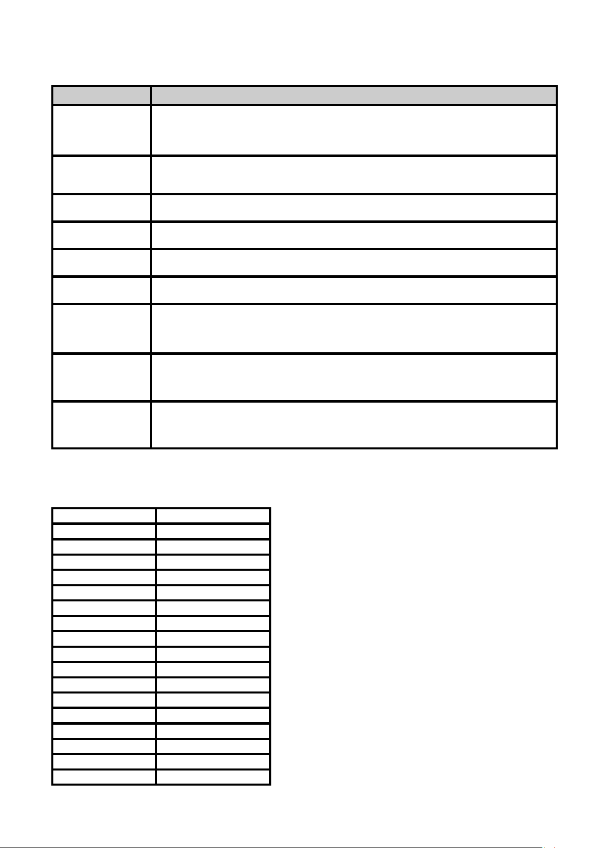
68
MEASURE
DEFINITION
Total stack losses:
Measure of nitrogen oxides quantity; the measurement unit can be set in the special
Measure of nitrogen oxides quantity; the measurement unit can not be set but it is fixed in
Measure of nitrogen oxides quantity referring to O2; the measurement unit can be set in
Measure of nitrogen oxides quantity referring to O2; the measurement unit can not be set
Poison Index (CO/CO2 ratio):
ppm p
mg/m3 g
mg/Kwh w
g/m3 G
g/Kwh W
g/GJ J
ng/J J
hPa h
Pa P
mbar b
mmH2O H
mmHg g
inH2O i
psi p
°C C
°F F
m m
ft
ft
Total efficiency in relation to the Higher Heating Value:
ηt (HHV)
Total efficiency. It is the sum of sensible efficiency and condensation efficiency. It is referred to HHV (Higher Heating Value) and can not exceed 100%.
Qt (HHV)
It is the total heat percentage dissipated through the stack.
NOx
NOx ppm *
NOx (rif. O2)
NOx (rif. O2) ppm *
menu.
ppm.
the special menu.
but it is fixed in ppm.
PI
It is defined as the ratio between CO and CO2 useful to determine whether the system
needs maintenance.
CO
CO (RIF)
CO quantity measurement. Measurement units: ppm - mg/m3 - mg/kWh - ng/J - g/GJ -
3
g/m
- %
CO quantity measurement with O2 reference. Measurement units: ppm - mg/m3 - mg/kWh
- ng/J - g/GJ - g/m3 - %
* : Valid for Piemonte region only (Italy only).
Measurement units matching → abbreviations
Page 73

69
Coefficients for calculating combustion efficiency
Natural Gas
0,0280
0,0090
11,70
50050
55550
17,17
2,250
11,94
Propane
0,0277
0,0073
13,70
45950
49950
15,61
1,638
11,11
#2 Oil
0,0305
0,0066
15,70
42900
45700
14,30
1,136
10,34
#4 Oil
0,0306
0,0066
15,80
41100
43500
13,80
0,973
10,06
#6 Oil
0,0346
0,0048
16,00
39800
42197
13,61
0,981
9,97
Diesel
0,0305
0,0066
15,70
42900
45700
14,30
1,136
10,34
Wood/Pellets 8%
0,0354
0,0071
19,01
18150
19750
6,02
0,660
4,58
Bagasse
0,0395
0,0219
20,45
6950
8834
2,50
0,779
1,93
Coal
0,0320
0,0000
18,60
31400
32300
10,70
0,370
8,14
Biogas
0,0353
0,0091
17,33
17800
19800
6,08
0,830
4,55
Bio-Fuel 5%
0,0305
0,0066
15,70
42600
45400
14,22
1,133
10,64
L.P.G.
0,0277
0,0073
13,80
45730
49650
15,52
1,602
11,03
Butane
0,0277
0,0073
14,00
45360
49150
15,38
1,548
10,99
ANNEX D
Coefficients of the fuels and Formulas
The following chart, lists the coefficients of the memorised fuels, used for calculating losses and efficiencies.
Details of the coefficients of the fuels:
Fuel A1 USA
B
CO2t
(%)
PCI
(KJ/Kg)
PCS
(KJ/Kg)
M air
(Kg/Kg)
M H2O
(Kg/Kg)
V dry gas
•
CO2 t: The value of CO2 generated by combustion in stoichiometric condition, i.e. without excess Oxygen
and therefore maximum.
•
A1, B: Also please have a look at the Siegert formulas from the European standard EN50379-1 (in the
following).
A1 is the parameter in the Siegert Formula when the O2 measurement is available.
Note: - Please also consider that in the U.S. usually the A1 parameter is the same as the
'European' A1 BUT divided by 2.
Flue gas heat losses are calculated from measured oxygen content according to the relationship:
qA = (tA - tL) x A1
Flue gas heat losses are calculated from measured carbon dioxide content according to the relationship:
qA = (tA - tL) x A1
Air index is calculated with the formula:
21
21 - O
t
CO
2
CO
2
2
+
+
(m3/Kg)
λ=21/(21-O2), where O2 is the oxygen residual concentration in the combustion smokes.
Air excess is calculated with the formula:
e=(λ-1)*100
•
CO conv: Conversion coefficient from ppm to mg/KWh. It can be expressed as a function of the gas density
•
NO conv: Same as CO conv, but for NO.
•
NOx conv:Same as CO conv, but for NOx.
•
SO2 conv: Same as CO conv, but for SO2.
•
PCI: Potere Calorifico Inferiore. Italian for LHV (Lower Heating Value).
•
PCS: Potere Calorifico Superiore. Italian for HHV (Higher Heating Value).
•
m H2O: Mass of the air produced (per each Kg of fuel) in the combustion in stoichiometric condition.
•
m Air: Mass of the air needed for combustion in stoichiometric condition.
•
V g.d.: Volume of dry smokes produced in the combustion.
(CO in this case) and the volume of the dry smoke.
Page 74

ANNEX E
DECLARATION OF CONFORMITY
The manufacturer: E Instruments by Sauermann
with registered address in: KIMO S.A. - CS 5001 - 24700 MONTPON - FRANCE
declares that the following products: E500
is in conformity with the essential requirements of directives 2014/30/UE and 2014/35/CE.
The instrument is in conformity with the requirements of the European standards
EN 50379-1 and EN 50379-2 for the following measurements:
O2
CO
Temperature (flue gas)
Temperature (supply air)
Pressure (draft)
Pressure (differential)
Page 75

NT_EN_E500 _ 03/09/19 – We reserve the right to modify the characteristics of our products without prior notice.
 Loading...