

Page 1
t
Operating Instructions for the
Indoor and Outdoor Device
Split-system Air Conditioner
Important note:
This high-quality product will only offer
optimum service if installed correctly and in
the right place, and is put into operation for
the first time by a suitably competent person.
Avoid malfunctions by seeking competent
advice from an expert with regards to the
location, installation and starting up of the
system.
We shall accept no liability for malfunctions
or inadequate cooling performance resulting
from the improper handling of the product.
Only a suitably qualified firm is permitted to
undertake any work of making the electrical
and cooling system connections and putting
the system into operation for the first time.
If the system is to be moved to another
location or disposed of, only a suitably
qualified electricianʼs/cooling system firm is
permitted to undertake any work of
disassembly or disposal.
Art.-Nr.: 23.658.25 I.-Nr.: 01017
NSK 3503 IS C+H
Anleitung_NSK_3503_IS_C_H_GB:_ 28.03.2008 10:14 Uhr Seite 1
Page 2
2 3
1
B
A
C
I
H
J
F
L
M
N
E
2
1/3
2
3
7/8
9
5/6
4
1
O
P
Q
K
G
D
2
Anleitung_NSK_3503_IS_C_H_GB:_ 28.03.2008 10:14 Uhr Seite 2
Page 3
5
8
7
9
1
1
2
3
2
3
6
4
7
9
8
5
4
1
2
3
4
5
1
2
3
4
5
4
6
1
2
3
5
6
4
2
3
Anleitung_NSK_3503_IS_C_H_GB:_ 28.03.2008 10:14 Uhr Seite 3
Page 4
10 11
12
13
A
1
2
3
2
1
1
2
3
4
5
6
4
Anleitung_NSK_3503_IS_C_H_GB:_ 28.03.2008 10:14 Uhr Seite 4
Page 5
16
15
Ø 65 Ø 65
> 15 cm
> 15 cm
> 300 cm
> 230 cm
> 15 cm
> 50 cm
> 30 cm
> 30 cm
> 50 cm
> 200 cm
14
17 18
A
B
5
Anleitung_NSK_3503_IS_C_H_GB:_ 28.03.2008 10:14 Uhr Seite 5
Page 6
6
19
21 22
2423
20
B
D
A
C
Anleitung_NSK_3503_IS_C_H_GB:_ 28.03.2008 10:15 Uhr Seite 6
Page 7
7
2625
A
Anleitung_NSK_3503_IS_C_H_GB:_ 28.03.2008 10:15 Uhr Seite 7
Page 8

Important!
When using the equipment, a few safety precautions
must be observed to avoid injuries and damage.
Please read the complete operating instructions and
safety regulations with due care. Keep this manual in
a safe place, so that the information is available at all
times. If you give the equipment to any other person,
hand over these operating instructions and safety
regulations as well. We cannot accept any liability for
damage or accidents which arise due to a failure to
follow these instructions and the safety instructions.
1. Safety instructions
앬 Read the safety instructions before you start to
use the device.
앬 These points set out extremely important
precautionary measures that you must comply
with.
앬 Keep the Operating Instructions in a safe place
once you have read them.
앬 Check that the drainage line is correctly
connected. If not, water will escape.
앬 Warning!
Do not extend the cable and never use multiple
plugs. A poor electrical connection, poor
insulation or voltage which is higher than
permitted can cause fire.
앬 Remove all dirt from the power plug and plug
it in firmly. Soiled plugs can cause fire or an
electric shock.
앬 Warning!
앬 Never pull out the plug while the device is in use.
앬 Never permit cool air to be blown directly at you
for any lengthy period of time.
앬 In the event of any abnormalities (e.g. smell of
burning), immediately switch off the device and
pull the plug. Contact your service partner.
앬 Never poke fingers or sticks in the air inlet and
outlet vents.
앬 Never attempt to repair the air conditioner
yourself. Always contact your service partner if it
requires repair.
앬 Never pull the plug out by pulling on the cable.
Hold the plug firmly and pull it out of the plug
socket, otherwise there is a risk of damaging the
cable.
앬 Always switch off the device and pull the plug
before you start to clean it.
앬 Never actuate any switches with wet hands.
앬 Never clean the air conditioner with water.
앬 Never place any plants or animals under a
location to which cool air flows as this could have
an undesirable affect on them.
앬 Never use combustible cleaning agents as these
could cause a fire or deformation.
앬 If the air conditioner is to be used in conjunction
with other heaters, the air should be refreshed
periodically, otherwise there is a risk of lack of
oxygen.
앬 Never use the device for any other purpose than
the intended use. Never place food, precision
instruments, plants, animals, paint, etc. on the
device.
앬 Never hold any burning objects close to the
device if they could be directly affected by the
emitted air.
앬 Always pull out the power plug if the device is not
going to be used for any lengthy period of time.
Collections of dust can cause fire.
앬 Never step onto the outdoor device and never
place anything on it.
앬 Never use an unsteady or rusty base.
앬 Never allow the device to run for too long with the
doors or windows open, or if the humidity is very
high. If the air conditioner runs for a long time in
cooling mode and the humidity is high (over
80%), condensed water may drip out of the
device.
앬 Never stand on an unsteady base when you
remove the device from the holder on the wall.
앬 Check that the condensation water can run off
unhindered. Water damage can result if the
condensation water cannot run off properly.
앬 Never touch any metal parts on the indoor device
when removing the air filter. You may injure
yourself.
앬 Never install the device in a room in which
combustible gases can be emitted. Emitted
gases may collect and cause an explosion.
앬 Always switch off the device and pull out the
power plug during a storm. Electrical parts may
get damaged.
앬 Earthing connection!
The power cable (plug) comes with an earthing
wire. Do not, therefore, change the plug.
앬 For electrical safety purposes we recommend
that you install an earth-leakage circuit-breaker.
앬 Have all electrical installation work performed by
a qualified electrician.
앬 Ask a service partner or specialist cooling system
firm to undertake all work of cooling systemrelated installation.
앬 Incorrect installation may cause injury or damage
to the device.
앬 Check the mains lead at regular intervals for
signs of defects or damage. A damaged mains
lead may only be replaced by an electrician or
ISC GmbH in compliance with the relevant
regulations.
8
GB
Anleitung_NSK_3503_IS_C_H_GB:_ 28.03.2008 10:15 Uhr Seite 8
Page 9

앬 The equipment is not designed for installation in
laundries.
앬 The equipment must be positioned in such a way
that the mains plug is accessible at all times.
앬 The temperature in the cooling circuit may
become very hot. For this reason keep all cables
away from the copper lines.
CAUTION!
Read all safety regulations and instructions.
Any errors made in following the safety regulations
and instructions may result in an electric shock, fire
and/or serious injury.
Keep all safety regulations and instructions in a
safe place for future use.
Packaging:
The unit is supplied in packaging to prevent it from
being damaged in transit. The raw materials in this
packaging can be reused or recycled.
Tips on saving energy
Only use the air conditioner when you really need to.
Do not select too high a temperature for heating or
too low a temperature for cooling. Select the “Sleep”
function during the night.
Close all windows, doors and Venetian blinds in
order to reduce incoming sunlight as far as possible.
Principle of operation for cooling
Heat is extracted from the air in the room by the air
heat-exchanger (evaporator) in which the coolant
circulates. This air is conveyed to the outside air
heat-exchanger (condenser).
This gives off heat to the outdoor air. Electrical
energy is required for this. In certain circumstances
condensation may form on the evaporator on the
indoor unit, which will be removed by the
condensation hose.
Function principle – heating
In heating mode, heat is removed from the outdoor
air by the outdoor device and fed into the indoor
device. This passes the heat on to the room which it
is to heat. Electrical energy is required for this. In
certain circumstances condensation may be
produced on the outdoor device, which must be
discharged via the condensation drain on the
underside of the outdoor device.
Inverter
In both modes of operation, the compressor capacity
adjusts to the demand and regulates the nominal
temperature with minimum temperature fluctuations.
This “inverter technique” saves energy compared to
conventional split air-conditioning systems.
2. Items supplied
1 indoor device (box 1, art. no. 23.654.48)
1 outdoor device (box 2, art. no. 23.654.49)
1 set of installation accessories (for details, see page
15)
3. Technical data
Cooling capacity 3600 watts
Heating capacity 3900 watts
Power rating in cooling mode 1100 watts
Power rating in heating mode 1200 watts
Energy efficiency A (EER 3.27/COP 3.25)
Air capacity 500 m3/h
Absorbed humidity (30°C/80% RH) 1.2 l/h
Timer 24 h
Operating voltage 220 - 240 V ~ 50 Hz
Socket fusing 16 A
Nominal power consumption, cooling (EN 60335)
1600 watts
Nominal current consumption, cooling 7 A
Nominal power consumption, heating (EN 60335)
1650 watts
Nominal current consumption, heating 7.2 A
Compressor Rotary piston
Compressor starting current 33 A
Outdoor temperature, cooling operation °C
+18 - + 43 (DB)
Outdoor temperature, heating operation °C
-10 - + 24 (DB)
Fluid line Ø A 6,35 mm
Suction pipe Ø A 12,7 mm
Length of refrigerant line supplied 4 m
Length of refrigerant line, max. 10 m
Max. difference in height between indoor/outdoor
device 5 m
Refrigerant R 410 A
Refrigerant filling capacity 1270 g
Refrigerant refill quantity from 5 m 25 g/m
Sound pressure level
Inside ≤ 40 dB (A)
Outside ≤ 54 dB (A)
Dimension Inside 100,5 x 29 x 15 cm
Dimension Outside 84,8 x 54 x 32 cm
9
GB
Anleitung_NSK_3503_IS_C_H_GB:_ 28.03.2008 10:15 Uhr Seite 9
Page 10

Weight Inside 11 kg
Weight Outside 40 kg
Note:
The specified capacities and performances are
based on the following conditions (EN 14511):
Cooling:
Air temperature at the inlet on the indoor device:
27°C for dry thermometer bulb (DB), 19°C for wet
thermometer bulb (WB). Outdoor air temperature:
35°C for dry thermometer bulb (DB), 24°C for wet
thermometer bulb (WB). Maximum air delivery rate.
Heating:
Air temperature at the inlet on the indoor device:
20°C for dry thermometer bulb (DB), 15°C for wet
thermometer bulb (WB). Outdoor air temperature:
7°C for dry thermometer bulb (DB), 6°C for wet
thermometer bulb (WB). Maximum air delivery rate.
Temperature ranges:
Cooling
Room temperature 16°C ~ 30°C
Outdoor temperature 18°C ~ 43°C
Heating
Room temperature 16°C ~ 30°C
Outdoor temperature - 10°C ~ 24°C
Dehumidifying
Room temperature 16°C ~ 32°C
Outdoor temperature 18°C ~ 43°C
Notes:
1. For health reasons the room temperature should
be no more than 5 – 6°C below the outdoor
temperature in cooling mode.
2. The perfect performance of the system is
achieved within the temperature ranges shown in
the table.
3. If the air conditioning system is operated below
the temperature range shown above, protection
functions may be activated in certain
circumstances which will cause the device to
operate abnormally.
4. If the air conditioner is operated in a relative
humidity level of over 80%, condensation may be
deposited on the top of the system which will
then drip on to the floor. In this case set the
horizontal air flap to its maximum angle
(perpendicular to the floor) and set the FAN to
“HIGH”.
4. Intended use
The air-conditioning system is only designed for airconditioning privately used dry rooms with a
maximum room volume of 115 m
3
. The room volume
depends on the local conditions. Large window
areas, additional heat sources (PC, television,
people, etc.), poor wall insulation, etc. serve to
reduce this room volume.
The machine is to be used only for its prescribed
purpose. Any other use is deemed to be a case of
misuse. The user / operator and not the
manufacturer will be liable for any damage or injuries
of any kind caused as a result of this.
Please note that our equipment has not been
designed for use in commercial, trade or industrial
applications. Our warranty will be voided if the
machine is used in commercial, trade or industrial
businesses or for equivalent purposes.
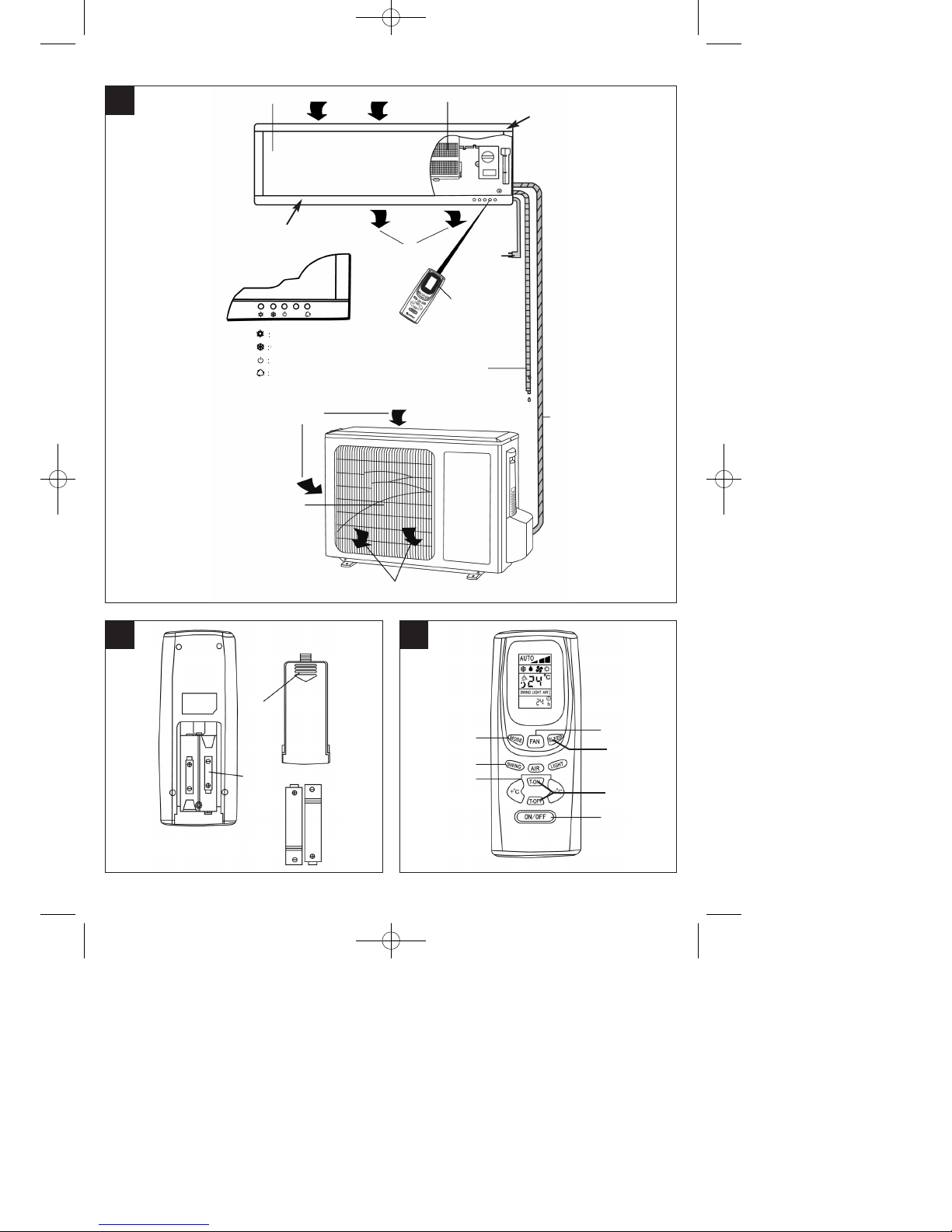
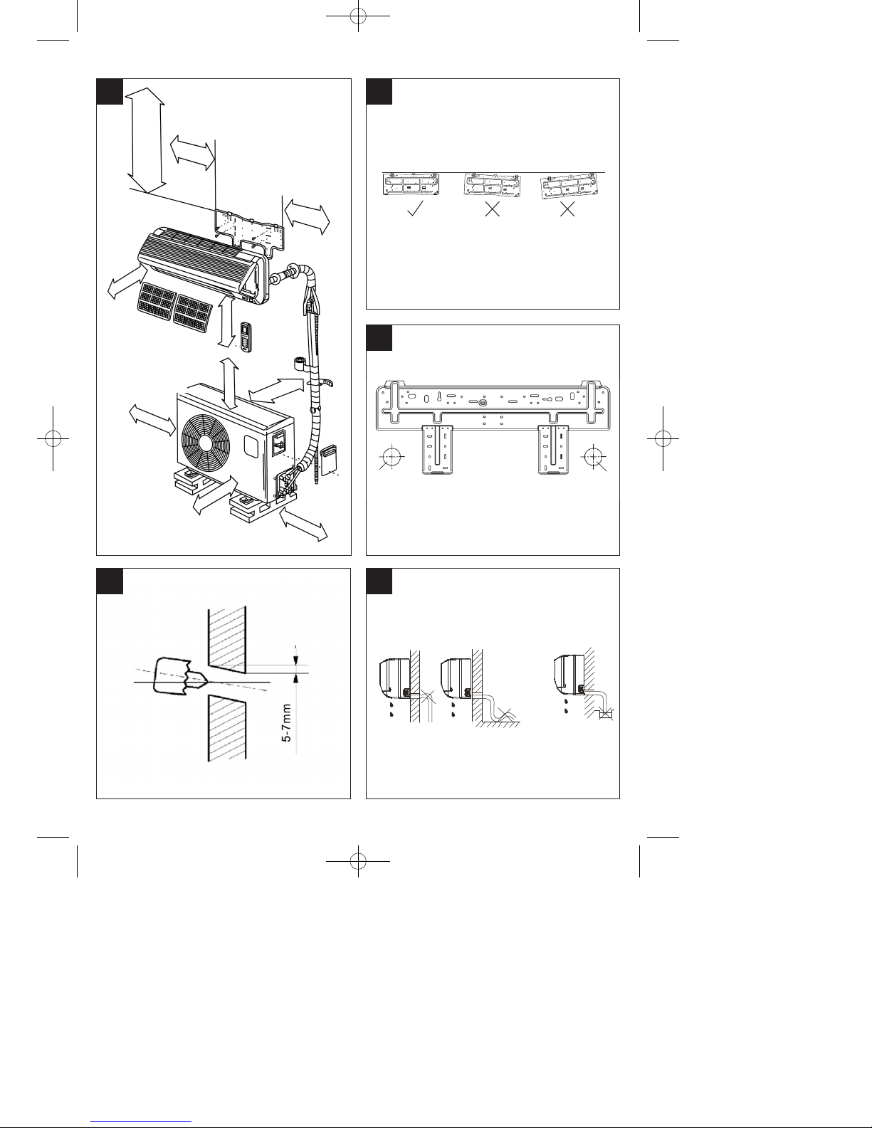
5. Description of parts (Fig. 1)
A: Air inlet
B: Cover
C: Air filter
D: Housing
E: Emergency switch for automatic operation
F: Air outlet
G: Slat
H: Power cable
I: Infrared remote control
J: Condensation water hose
K: Refrigerant line
L: Heating
M: Cooling/dehumidifying
N: Operating display
O: Air inlet
P: Air outlet grille
Q: Air outlet
6. Setting up the remote control (Fig. 2)
Insert batteries
1. Open the battery compartment cover.
2. Insert two new batteries. Be sure to observe the
correct polarity (+/-) of the batteries.
3. Close the battery compartment cover.
Notes
앬 The radio signal has a range of approx. 8 m.
앬 Use two alkali batteries, type R03 AAA (1.5 V).
10
GB
Anleitung_NSK_3503_IS_C_H_GB:_ 28.03.2008 10:15 Uhr Seite 10
Page 11

앬 Always replace both batteries at once when you
can no longer see the LCD display.
앬 Never use a combination of new and used
batteries.
앬 Never use a battery type other than the specified
one.
앬 If the remote control is not used for a lengthy
period of time, remove the batteries to prevent
them leaking.
앬 The service life of the batteries if the remote
control is used normally is approximately 12
months.
앬 Dispose of spent batteries properly.
Notes
Keep the remote control approximately 1 m from
television sets or other electrical appliances. Direct
sunlight may considerably reduce the range of the
remote control.
Objects between the remote control and the IR
receiver which can impede reception of the signal
must be avoided. Handle the remote control with
care. Do not drop it, keep it away from heat and
moisture so as not to damage the remote control.
7. Functional description of the remote
control
Key assignment (Fig. 3)
1 “Mode” (operating mode) key
2 “Fan” (fan speed) key
3 “Sleep” (sleep function) key
4 “Swing” (automatic, horizontal slat adjustment)
key
5 “+ °C” (temperature increase) key
6 “- °C” (temperature decrease) key
7 “T-ON” (device ON timer) key
8 “T-OFF” (device OFF timer) key
9 “ON-OFF” (device ON/OFF) key
“AIR” and “LIGHT” keys are not assigned
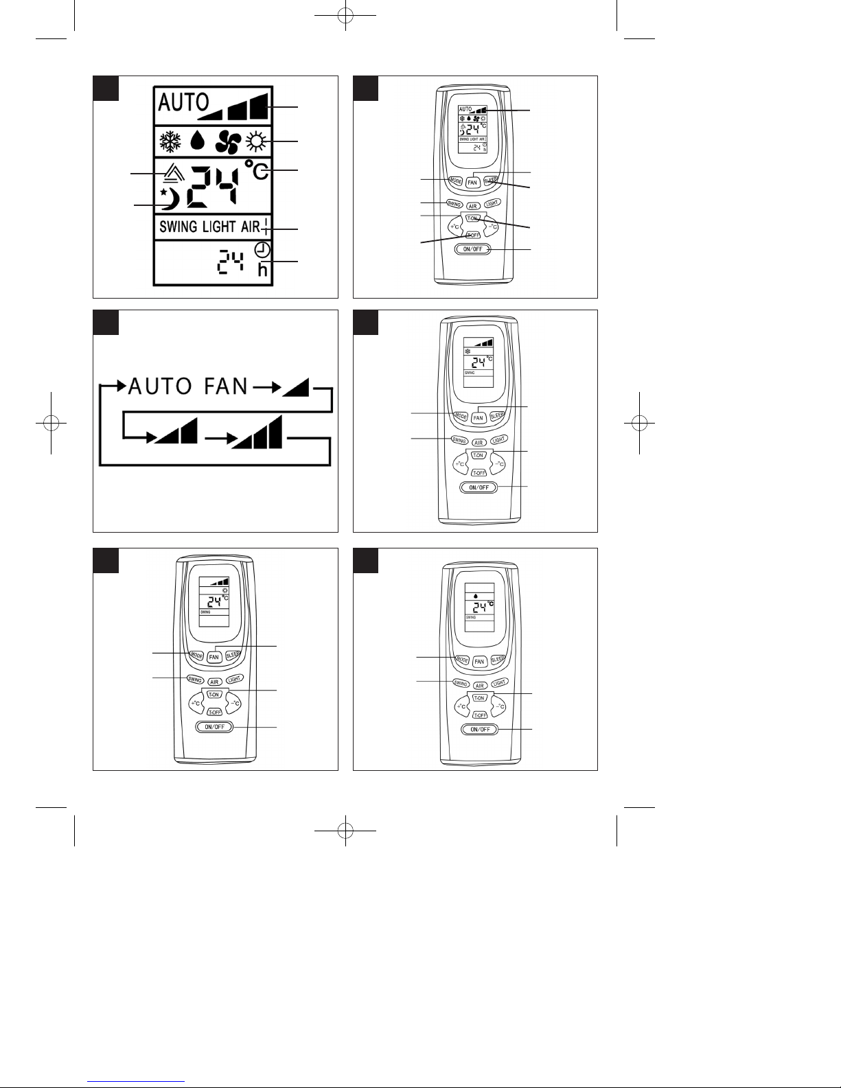
Display (Fig. 4)
1 “Fan speed” display
2 “Mode” display
3 “Temperature” display
4 “Sleep mode” display
5 “Slat adjustment” display
6 “Timer” display
Remote control brief description
(Fig. 5-6)
1 “Mode” (operating mode) key
This key is used to select one of the available
operating modes. The operating mode changes in
the following sequence per key press:
Automatic -> Cooling -> Dehumidifying -> Fan ->
Heating
2 “Swing” (automatic, horizontal slat adjustment)
key
Press this key once for electric, horizontal slat
adjustment. The air flow is adjusted
upwards/downwards.
Press the key twice to lock the slats in their current
position.
3 “+ °C” (temperature increase) and “- °C”
(temperature decrease) keys
Press the “+ °C” key once to increase the set
temperature by 1°C. Press the “-°C” key once to
decrease the set temperature by 1°C.
The temperature can be set from 16°C to 30°C on
the remote control via the “Cooling”, “Dehumidifying”
and “Heating” operating modes.
The temperature cannot be set in the “Automatic”
and “Fan” modes.
4 “Fan” (fan speed) key
The fan speed changes in the following sequence
per key press:
Automatic -> Slow -> Medium -> Fast
5 “ON-OFF” (device ON/OFF) key
This key is pressed to switch the device on and off.
6 LCD display
All settings are displayed.
7 “Sleep” (sleep function) key
Press this key once to activate the sleep function.
Press the key twice to switch the function back off.
8 “T-ON” (device ON timer) key
Press this key to automatically switch on the device
within a 0.5 and 24 hour range.
9 “T-OFF” (device OFF timer) key
Press this key to automatically switch off the device
within a 0.5 and 24 hour range.
Note:
The “AIR” and “LIGHT” keys are not assigned and do
not influence the device when pressed.
11
GB
Anleitung_NSK_3503_IS_C_H_GB:_ 28.03.2008 10:15 Uhr Seite 11
Page 12

Operating modes
A) Cooling mode (Fig. 7)
1. Press the “ON/OFF” key to switch on the device.
2. Press the “MODE” key until the “Cooling” mode
icon appears in the display.
3. Press the “Swing” key. The air flow is adjusted
upwards/downwards. Press the key twice to lock
the slats in their current position.
4. Press the “FAN” key to select the fan speed:
Automatic -> Slow -> Medium -> Fast
5. Press the “+°C” or “-°C” key to set the desired
temperature.
Notes!
앬 The cooling mode will only work if the room
temperature set is lower than the current room
temperature. When the set room temperature is
reached, the outdoor compressor stops. The
centrifugal fan of the indoor device circulates the
air in the room.
앬 The set room temperature should not be more
than 5°C below the outdoor temperature
(example: outdoor temperature 30°C, ideal room
temperature 25°C).
앬 The room temperature can be set between 16°C
and 30°C with the remote control.
앬 The higher the outdoor temperature, the higher
the attainable indoor temperature
B) Heating mode (Fig. 8)
1. Press the “ON/OFF” key to switch on the device.
2. Press the “MODE” key until the “Heating” mode
icon appears in the display.
3. Press the “Swing” key. The air flow is adjusted
upwards/downwards. Press the key
twice to lock the slats in their current position.
4. Press the “FAN” key to select the fan speed:
Automatic -> Slow -> Medium -> Fast
5. Press the “+°C” or “-°C” key to set the desired
temperature.
Notes!
앬 The heating mode will only work if the room
temperature set is higher than the current room
temperature. When the set room temperature is
reached, the outdoor compressor stops. The
centrifugal fan of the indoor device circulates the
air in the room.
앬 The room temperature can be set between 16°C
and 30°C with the remote control.
앬 The attainable room temperature is a factor of
local conditions and the outdoor temperature.
The cooler the outdoor temperature, the lower
the attainable room temperature.
C) Dehumidifying mode (Fig. 9)
1. Press the “ON/OFF” key to switch on the device.
2. Press the “MODE” key until the “Dehumidifying”
mode icon appears in the display.
3. Press the “Swing” key. The air flow is adjusted
upwards/downwards. Press the key
twice to lock the slats in their current position.
4. Press the “+°C” or “-°C” key to set the desired
temperature.
Notes!
앬 The “Dehumidifying” mode only works if the
difference between the set room temperature
and the current room temperature is within
+/- 2°C.
앬 If the room temperature set for the
“Dehumidifying” mode is more than 2°C higher
than the current room temperature, the
compressor stops along with the fan in the
outdoor device. The centrifugal fan of the indoor
device is also switched off.
앬 If the room temperature set for the
“Dehumidifying” mode is more than 2°C below
the current room temperature, the device runs in
cooling mode.
앬 The room temperature can be set between 16°C
and 30°C with the remote control.
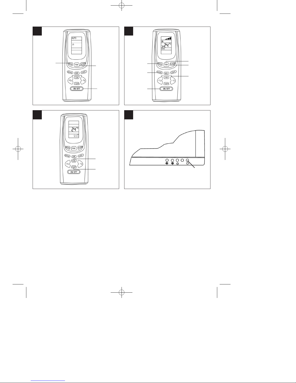
D) Automatic mode (Fig. 10)
1. Press the “ON/OFF” key to switch on the device.
2. Press the “MODE” key until the “Automatic” mode
icon appears in the display. The device automatically switches to cooling, fan or heating mode,
depending on the current room temperature.
3. Press the “FAN” key to select the fan speed:
Automatic -> Slow -> Medium -> Fast
Notes!
앬 When “Automatic” mode is selected, the room
temperature is fixed at 25°C for cooling and 20°C
for heating. These temperatures cannot be
changed.
앬 When the current room temperature is between
23°C and 26°C in “Automatic” mode, the device
runs as a fan without the effect of heating or
cooling.
앬 When the current room temperature is greater
than 26°C in “Automatic” mode, the device runs
with a cooling effect.
앬 When the current room temperature is below
22°C in “Automatic” mode, the device runs with a
heating effect.
E) Sleep function (Fig. 11)
1. Press the “ON/OFF” key to switch on the device.
2. Press the “MODE” key until the “Cooling”,
12
GB
Anleitung_NSK_3503_IS_C_H_GB:_ 28.03.2008 10:15 Uhr Seite 12
Page 13

“Dehumidifying” or “Heating” mode icon
appears in the display.
3. Press the “Swing” key. The air flow is adjusted
upwards/downwards. Press the key
twice to lock the slats in their current position.
4. Press the “FAN” key to select the fan speed:
Automatic -> Slow -> Medium -> Fast
5. Press the “+°C” or “-°C” key to set the desired
temperature.
6. Press the “Sleep” key to activate the sleep
function.
Notes!
앬 If the cooling or dehumidifying mode is set in
conjunction with the sleep function, the set room
temperature increases (1°C during the first hour
and 2°C during the second hour) in order to
prevent overcooling.
앬 If the heating mode is set in conjunction with the
sleep function, the set room temperature
decreases (1°C during the first hour and 2°C
during the second hour) in order to prevent
overheating.
F) Timer settings (for automatically switching the
device on/off) (Fig. 12)
1. “T-ON” (device ON timer) key
This key is pressed to automatically switch on the
unit. The only requirement is that the unit be
connected to a power supply. Each time the key is
pressed, the time setting changes by an increment of
0.5 hours within a 0.5 and 24 hour range. To switch
the “Device ON timer” back off, press the key again
after “24h” is displayed or switch off the device by
pressing the “ON/OFF” key.
2. “T-OFF” (device OFF timer) key
This key is pressed to automatically switch off the
unit. The only requirement is that the unit be in
operation. Each time the key is pressed, the time
setting changes by an increment of 0.5 hours within
a 0.5 and 24 hour range. To switch the “Device OFF
timer” back off, press the key again after “24h” is
displayed or switch off the device by pressing the
“ON/OFF” key.
8. Indoor device settings
Setting the vertical air flow direction
The left-hand and right-hand side flow directions can
be adjusted manually. Perform these adjustments
before you start the device because once it has been
started the slats vibrate and there is a risk of your
fingers getting caught.
Remote control fails to work (emergency
operation) (Fig. 13)
If the remote control fails to work (empty batteries or
malfunction), use the emergency switch (A).
앬 The device is off: After the emergency stop
switch has been pressed the device switches to
automatic mode. The slatadjuster also operates
in automatic mode.
앬 The device is on: The device switches off if the
emergency switch is pressed.
9. Cleaning notes
Important!
Switch the device off and pull the mains plug each
time before cleaning.
Note!
The time intervals at which the device should be
cleaned are a factor of the area of installation. The
time intervals listed below should be maintained in
most cases.
Keep the outdoor device and the area around the
outdoor device clean. Regularly remove leaves, etc.
which can collect around the outdoor device.
Cleaning the housing of the indoor device
앬 Clean the housing of the indoor device using
only a soft, wet cloth when necessary.
앬 In order to avoid damaging the housing and
electronics, avoid the use of gasoline, thinners,
scouring powder, cleaners and the like when
cleaning.
Cleaning the air filters of the indoor device
Make sure that the air filters are clean! Soiled air
filters reduce the air output of the device. The air
filters of the indoor device should be checked and, if
necessary, cleaned on a monthly basis.
1. Pull on the recess at the right and left by the
panel and open. The opening angle is limited by
the lateral guides.
2. Carefully pull the panel up out of the brackets
and fold the brackets back down.
3. Now lift the panel a little and remove the air
filters below.
4. Carefully vacuum off the air filters or wash them
using a neutral soap solution. Note that the water
temperature must not exceed 45°C, as the air
filters would then change in color and could
become distorted. Let the air filters dry in the
shade.
13
GB
Anleitung_NSK_3503_IS_C_H_GB:_ 28.03.2008 10:15 Uhr Seite 13
Page 14

5. To reinstall the air filters in the indoor device, lift
the panel a little and reinsert.
6. Lower the panel back down until it latches into
the panel brackets on the inner housing. Close
the panel. Replace the air filters once annually.
Replacement air filters can be obtained from
your service partner.
Cleaning the heat exchanger of the indoor device
The heat exchanger must be cleaned at least once
annually. To do this, remove the air filters from the
indoor device as described above.
앬 Using a vacuum cleaner or a long-bristled brush,
carefully remove any dirt deposits on the heat
exchanger; this will avoid damaging the heat
exchanger fins. A damaged heat exchanger will
lead to higher operating costs.
앬 Take steps to ensure that you do not injure
yourself on the fin edges!
10. General notes
After pressing the start key the device is not
started by the microprocessor for 3 minutes.
This is not a fault, it is for the protection of the
compressor. Please have a little patience.
Crackling noises can be heard.
This is not a fault. These tension noises are caused
by the contraction and expansion of the front panel in
response to temperature differences.
There is an odd smell in the room.
This is not a fault. The air conditioner also circulates
the transpiration from the walls, carpets, smoke,
furniture and clothing in the air.
You can hear moving water.
This is not a fault. The coolant in the air conditioner
may have expanded.
The air conditioner switches off during heat
mode. Heat mode is not possible if the outdoor
temperature is below approx. -10°C.
The outdoor device freezes if the outdoor temperature is low (below approx. -10°C).
Restarting after lengthy non-use
If the air-conditioning system has not been used for a
lengthy period, check the following before you switch
it on:
1. there are no objects covering the outdoor or
indoor unit.
2. the socket from which the unit is operated has
been installed correctly
3. the air filters are clean
Care precautions
If the air conditioner is not going to be used for some
period of time:
1. Let the fans run for 6 hours to allow the device to
completely dry out. Set the highest possible
temperature level while the fans are running.
2. Switch off the device and pull the power plug.
3. Clean the air filters and housing parts.
4. Remove all dirt from the outdoor unit.
5. Take the batteries out of the remote control.
11. Troubleshooting
Device does not start. Check the following:
1. Is voltage present at the plug socket outlet?
2. Check the plug fuse!
3. Is the timer set?
The device does not provide satisfactory cooling!
Check the following:
1. Has an appropriate temperature been set?
2. Is the air filter soiled? Clean and fit back in place.
3. Are the inlets and outlets on the outdoor device
blocked?
4. Has the sleep mode been set during the day?
5. Are the connections between the indoor and
outdoor device adequately sealed? There may not
be enough coolant? If so, please contact your
service company.
In the event of a power failure, check the
following:
Press the ON/OFF key after a power failure. If the
problems remain after checking through the above
points, switch off the device and contact your service
company.
GB
14
Anleitung_NSK_3503_IS_C_H_GB:_ 28.03.2008 10:15 Uhr Seite 14
Page 15
GB
15
The following pages are intended for
professional installers.
Important
Do not hesitate to contact our service partners. They
will be able to give you a speedy response to all your
questions so that your system can be installed
correctly.
12. Installation accessories
Before you start to install the devices, please check
that all the installation accessories have been
supplied.
1 mounting plate for the indoor device
1 infrared remote control
2 batteries (type AAA, 1.5 V)
1 condensed water hose (L = 2 m)
1 sealing compound
1 wall hole cap
1 roll of plastic wrapping tape
1 set of refrigerant lines (L = 4 m)
13. Installation instructions (Fig. 14)
Check that the actual mains voltage is the same
as the mains voltage specified on the rating
plate.
앬 Use only suitable fastening material.
앬 Important. Make sure that there are no electric
cables or other installations (for example water
pipes) near the drill holes.
앬 Earth the outdoor device in accordance with
current regulations.
앬 The device must have separate protection
against short-circuits.
앬 Have all work of electrical installation performed
by an electrician.
앬 Ask a service partner or specialist cooling
system firm to undertake all work of installing the
cooling system.
앬 Incorrect installation can lead to injury or damage
to property.
앬 Always wear ear muffs, goggles and work gloves
when performing work of installation.
Notes on electrical connection!
All electrical connection work must be performed by
a qualified electrician authorized to do so such work
by the applicable electricity supply company. The
system must have separate protection against short-
circuits. Select a suitably large cable cross-section.
The yellow/green wire is to be used as a protective
conductor only and under no circumstances as a
voltage carrying conductor. The fixed electrical
connection of the device must be capable of being
isolated from the mains power supply by a device
with an isolating distance of at least 3 mm (e.g.
circuit-breaker).
Connect the electrical connections of the indoor and
outdoor devices together first and then connect to
the mains power supply. Check first that the entire
system is voltage-free. Secure the system from being
switched on again.
A. Selecting the place of installation
Indoor device
1. The openings for the inlet and outlet air must
never be covered, otherwise the air will not be
distributed throughout the entire room.
2. Install the indoor device in a location which
ensures that the distance through the wall to the
outdoor device is as short as possible.
3. Make sure that the drainage hose does not have
any kinks or upward inclines when you connect it
with the outside.
4. Do not select a location adjacent to a source of
heat, high humidity or inflammable gas.
5. Select a location which is firm enough for
installation so that the device is not subjected to
vibrations.
6. Check that the device has been installed
correctly and exactly.
7. Make sure that there is sufficient space available
for later repair and service work.
8. The device should be installed at a distance of at
least 1 m from all other electrical devices and
installations, e.g. TV, radio, computer, etc.
9. Select a location for the device which is easily
accessible so that the filter can be cleaned or
replaced without difficulty.
10. The maximum distance between the standard
indoor unit and outdoor unit is 4 m. The
maximum possible length of the refrigerant line is
10 m with a maximum height difference of 5 m.
11. Avoid direct sunlight.
Outdoor device
1. Select a location which avoids causing a
nuisance to neighbours from noise and air
emissions from device.
2. Select a location which is sufficiently well
ventilated.
3. Never cover the air inlets and outlets.
4. The location must be sufficiently firm for
installation and the prevention of vibrations.
Anleitung_NSK_3503_IS_C_H_GB:_ 28.03.2008 10:15 Uhr Seite 15
Page 16
16
GB
5. There must be no risk presented by combustible
gas or gas escaping as a result of corrosion.
6. Check that the device is installed in accordance
with regulations.
7. It should be installed at least 20 cm above the
expected snow line. Snow must not be allowed
to get into the outdoor unit.
8. The wall for installation must be strong and
capable of supporting the weight of the unit.
9. The device must not be exposed to strong gusts
of wind.
10. Make sure that the device is well ventilated and
kept free of dust. Avoid direct exposure to rain
and sunlight.
11. Install on a firm base, avoiding excessive noise
or vibrations.
Important:
The following could cause malfunctions.
Check with your service company in order to
prevent possible malfunctions at a later date.
The following locations should be avoided for
installation:
앬 A location where oil (machine oil) is stored.
앬 A location where there is a high salt content.
앬 A location with numerous sulphurous sources,
e.g. spa zones.
앬 A location where radio transmitters or amplifier
aerials, welding equipment or medical equipment
are in use.
앬 A location where the outdoor device is exposed
to direct sunlight. If necessary the device must
be protected with a sun-shade. Such a sunshade must not interfere with the air flow,
however.
앬 A location in the vicinity of heat or steam
generators.
앬 A location which is heavily exposed to dust.
앬 A location to which the general public have
access.
앬 A location with any other unusual characteristics.
Important!
앬 The direction in which the air is blown should
correspond with the prevailing direction of the
wind.
앬 Never install in locations exposed to aggressive
air.
앬 Comply with all specified minimum distances
(see Important notes on installation).
앬 The indoor and outdoor devices may only be
installed if they are in a horizontal position
measured using a spirit level. Check this after
you have completed the installation work.
앬 Do not kink or compressed the refrigerant lines.
앬 All the refrigerant lines, including connectors and
valves must be fitted with diffusion-resistant heat
insulation.
앬 Do not remove the protective caps from the
refrigerant lines / connections on the device until
immediately before you connect them.
앬 Open refrigerant lines must be protected from
the ingress of moisture by suitable caps or
adhesive tapes.
B. Installing the indoor device
It is imperative that you comply with the installation
instructions.
1. Before you start installation
앬 Select the location for the indoor device (follow
the previous notes on selecting the location for
installation).
앬 Check that the available mains voltage is the
same as the voltage specified on the rating plate.
앬 Fit appropriate insulation, supplied by the
customer, to the coolant tubes.
2. Fitting the mounting plate (Fig. 15/16)
앬 The mounting plate for the indoor device must be
fitted horizontally to the wall. In doing so, it is
imperative that you comply with all specified
distances. Mark and drill the holes for fastening
the mounting plate, and then firmly fasten with
dowels and screws. In order to prevent vibrations
on the indoor device, make sure that there are
no gaps between the wall and the mounting
plate.
3. Drilling holes through the walls (Fig. 16/17)
앬 Drill the hole through the wall for the lines/hoses
using a 65 mm drill bit, drilling from the inside (A)
to the outside (B) at an angle downwards of
approx. 5°. The ideal positions of the holes
through the walls are shown in Figure 16.
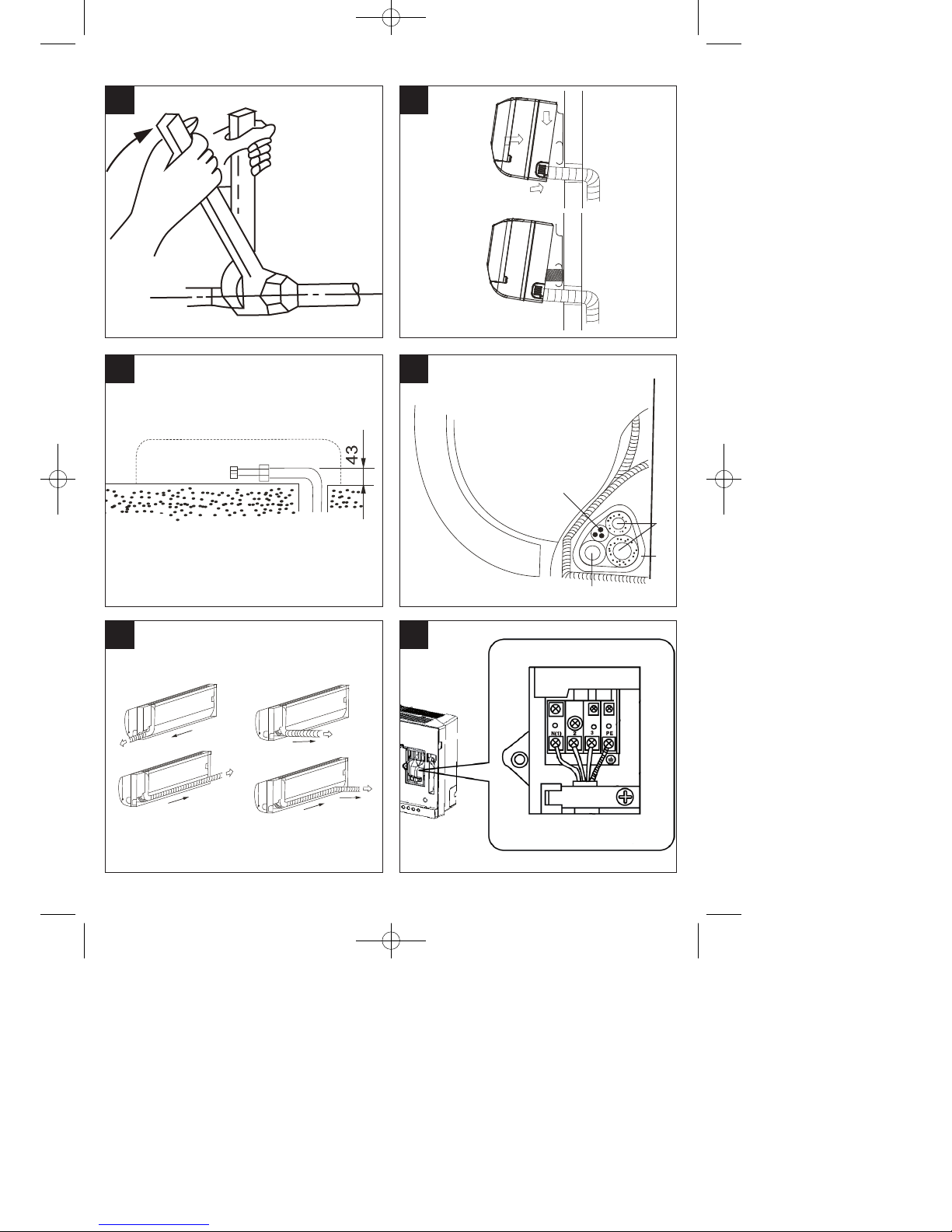
4. Fitting the condensation water drainage hose
(Fig. 18)
앬 The drainage water hose must be run to the
outside with a drop. It is imperative that there are
no bends or kinks. The end of the drainage hose
must not be situated in a container of any kind in
which water can collect. Any water held back in
the drainage water hose could lead to water
damage.
앬 Slide the additional drainage hose onto the
mounts on the drainage hose already fixed to the
indoor device. Fasten this connection point with
adhesive tape, checking that it is fully sealed as
you do so.
Anleitung_NSK_3503_IS_C_H_GB:_ 28.03.2008 10:15 Uhr Seite 16
Page 17

17
GB
Important note:
The following work must be carried out exclusively by
our service partner or a specialist refrigeration
contractor of your choice.
5. Connecting the refrigerant lines to the indoor
device (Fig. 19)
Route the refrigerant lines from the indoor device to
the outdoor device.
앬 Remove the plastic seals on the refrigerant
connection coupling on the indoor device and on
the respective refrigerant line.
앬 Fit the gland on the coolant tube straight on the
thread on the indoor device.
앬 Screw the first turns of the thread by hand in a
counterclockwise direction.
앬 Then use suitably sized open-ended wrenches to
tighten the glands. Please refer to the following
table for the applicable torque. Check the torque
using a torque wrench.
Ø 6,35 mm tube = 15 - 20 Nm
Ø 12,7 mm tube = 50 - 55 Nm
Notes:
앬 The top hook (Fig. 20) on the mounting plate
must be securely attached to the rear of the
indoor device. To simplify the connection of the
pipeline, the indoor unit is to be lifted away from
the wall at the bottom using a screwdriver or
similar. After you have connected the pipeline,
remove the screwdriver again and securely
attach the indoor device to the bottom hook (Fig.
20) on the mounting plate.
앬 Bend and position the pipeline carefully. (Fig. 21)
앬 Both refrigerant lines must be insulated at the
connection points.
앬 The condensation drain hose must be connected
below the refrigerant line.
앬 It must be ensured that none of the pipes on the
rear of the indoor device leak.
앬 It must be ensured that the condensation drain
hose is positioned at the lowest point of the
insulation package. The hose must be separated
from the cables and connection pipe so that no
condensation can run over the cables and pipe.
앬 Do not cross the mains cable with other cables.
6. Wrapping the lines/hoses in protective tape
(Fig. 22/23)
앬 Please note that the power cable is not to be fed
through to the outside. All tubes, electric cables
and the drainage water hose have to be wrapped
with the supplied protective tape. Depending on
whether the lines are right-hand or left-hand
versions, the corresponding bushing
preparations must be removed from the indoor
device.
앬 The package of lines/hoses is to be laid between
the housing of the indoor device and the wall.
Key for Fig. 22
A = Indoor / Outdoor device connection cable
B = Refrigerant line
C = Wrapping tape
D = Condensation drain hose
7. Final installation of indoor device
앬 Feed the package of lines/hoses through the
supplied wall passage. Position the wall passage
cap on the wall passage from the outside. Seal
the wall passage against the wall using the
supplied sealing compound.
8. Electrical connection
Important note: All work of making the electrical
connection of the system must be undertaken by an
electrician.
Use only the supplied connection cable or, if it is not
long enough, cable of exactly the same quality.
앬 Take the cover off the indoor device.
앬 Connect the cable to the indoor device as shown
on the connection diagram (Fig. 24).
(PE=yellow and green wire)
C. Installing the outdoor device
It is imperative that you follow the installation
instructions.
1. Before you start installation
앬 Select the location for installation (follow the
previous notes on selecting the location).
앬 Check that the available mains voltage is the
same as the voltage specified on the rating plate.
앬 The maximum possible distance between the
indoor and the outdoor device using the supplied
accessories is 4 m.
앬 If the outdoor device is higher than the indoor
device, make sure that a curve is made in the
coolant tube which is lower than the bottom edge
of the indoor device.
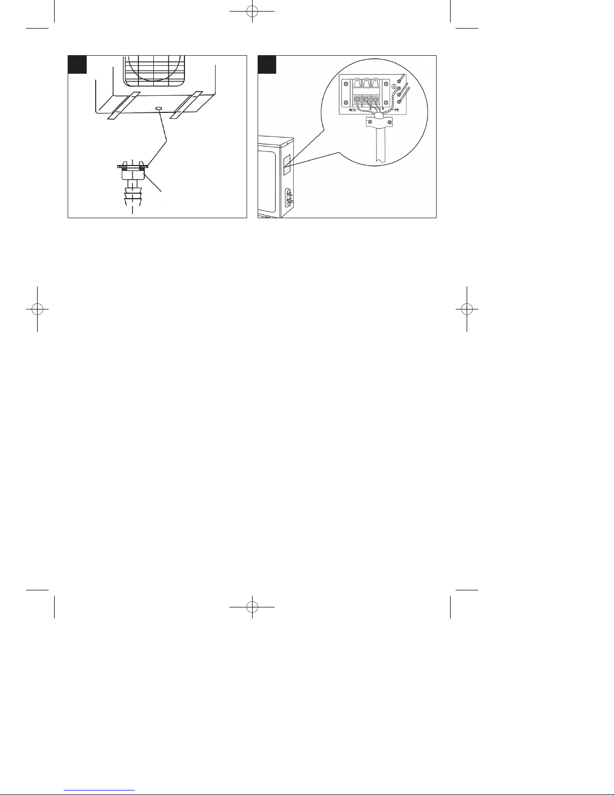
앬 Secure the condensation drain (A) to the base of
the outdoor device (Fig. 25). Drain the water
generated when the system is in heating mode
through a hose.
2. Installing the outdoor device
앬 The outdoor device can be fastened to the
ground or to a wall bracket (e.g. special
accessory Art. No. 23.651.57) with dowels and
screws. To do so, use the holes on the device.
Anleitung_NSK_3503_IS_C_H_GB:_ 28.03.2008 10:15 Uhr Seite 17
Page 18

D. Connecting the refrigerant lines
Proceed as described in section B.5 to connect the
refrigerant lines to the outdoor unit. Please read the
following information carefully.
1. Important notes
앬 Please make sure that coolant is never allowed
to enter the environment.
앬 Improper handling of coolant may be harmful to
health. Always wear work gloves and goggles
when handling coolant.
앬 Make sure that the work place is well ventilated
at all times. Smoking is prohibited.
앬 The device must never be operated without the
coolant tubes connected, otherwise the device
will be damaged immediately.
앬 Ask one of our service partners or a specialist
cooling system firm to connect the coolant lines
and put the system into operation for the first
time.
Important
1. Have all service work performed by a specialist
firm only. Request a copy of our list of service
partners for any such work.
2. If ever the voltage carrying cable between the
indoor device and the outdoor device should be
damaged, contact a specialist firm.
3. If the power cable should ever be damaged,
have it replaced by an electrician.
4. Important note:
a) The maximum length of the coolant line in the
basic version is 4 meters.
b) If the outdoor device is higher than the indoor
device, a curve will be required in the coolant
tube which is positioned below the height of the
indoor device.
Electrical connection (Fig. 26)
Important note: All work of making the electrical
connection of the system must be undertaken by an
electrician.
앬 Remove the connection cover on the outdoor
device.
앬 Connect the electric cable as shown in the
illustration; take account of the ground terminal
as you do so (PE=yellow and green wire).
앬 Ensure that the wire colors on the terminals of
the indoor device comply with those of the
outdoor device.
앬 Fit the connection cover back on the outdoor
device
After you have completed the installation of the
device, check its electrical safety.
14. Evacuation
The evacuation procedure may only be carried out
by an authorized expert. Draining refrigerant
damages the environment and is a criminal offence.
15. Initial startup
Initial startup must be performed by an authorized
specialist and documented.
a) Cool mode
앬 Switch on the voltage supply.
앬 Switch on the device using the remote control.
앬 Adjust the temperature setting to lower than the
current room temperature using the “TEMP”
button.
앬 Set “Cool” mode using the “MODE” button.
Please note that the full cooling capacity is not
achieved until the device has been operating for
approx. five minutes.
앬 Check all the functions as described in the
operating instructions.
앬 Measure and document all the required values
and check the safety functions.
앬 Check the condensate line by pouring distilled
water into the condensate tray, ideally using a
long neck bottle.
b) Heat mode
앬 Adjust the temperature setting to higher than the
current room temperature using the “TEMP”
button.
앬 Set “Heat” mode using the “MODE” button.
Please note that the full heating capacity is not
achieved until the device has been operating for
approx. five minutes.
앬 Check all the functions as described in the
operating instructions.
앬 Measure and document all the required values
and check the safety functions.
Then switch off the system, install any parts that you
have removed and show the operator how to use the
system.
GB
18
Anleitung_NSK_3503_IS_C_H_GB:_ 28.03.2008 10:15 Uhr Seite 18
Page 19

19
GB
16. Ordering replacement parts
Please quote the following data when ordering
replacement parts:
앬 Type of machine
앬 Article number of the machine
앬 Identification number of the machine
앬 Replacement part number of the part required
For our latest prices and information please go to
www.isc-gmbh.info
Anleitung_NSK_3503_IS_C_H_GB:_ 28.03.2008 10:15 Uhr Seite 19
Page 20

20
k
erklärt folgende Konformität gemäß EU-Richtlinie
und Normen für Artikel
t
declares conformity with the EU Directive
and standards marked below for the article
p
déclare la conformité suivante selon la
directive CE et les normes concernant lʼarticle
verklaart de volgende conformiteit in overeenstemming met de EU-richtlijn en normen voor
het artikel
m
declara la siguiente conformidad a tenor de la
directiva y normas de la UE para el artículo
O
declara a seguinte conformidade de acordo
com a directiva CE e normas para o artigo
U
förklarar följande överensstämmelse enl. EUdirektiv och standarder för artikeln
q
ilmoittaa seuraavaa Euroopan unionin direktiivien ja normien mukaista yhdenmukaisuutta
tuotteelle
erklærer herved følgende samsvar med EUdirektiv og standarder for artikkel
T
заявляет о соответствии товара
следующим директивам и нормам EC
B
izjavljuje sljedeću uskladjenost s odredbama i
normama EU za artikl.
Q
declarå urmåtoarea conformitate cu linia directoare CE μi normele valabile pentru articolul.
Z
ürün ile ilgili olarak AB Yönetmelikleri ve
Normlar∂ gere©ince aμa©∂daki uygunluk aç∂kla
mas∂n∂ sunar.
z
‰ЛПТУВИ ЩЛУ ·ОfiПФ˘ıЛ Ы˘МКˆУ›· Ы‡МКˆУ· МВ
ЩЛУ √‰ЛБ›· ∂∂ О·И Щ· ЪfiЩ˘Ф БИ· ЩФ ЪФ˚fiУ
C dichiara la seguente conformità secondo la
direttiva UE e le norme per lʼarticolo
l
attesterer følgende overensstemmelse i
henhold til EU-direktiv og standarder for produkt
j
prohlašuje následující shodu podle směrnice
EU a norem pro výrobek.
A
a következő konformitást jelenti ki a termékekre vonatkozó EU-irányvonalak és normák szerint
X
pojasnjuje sledečo skladnost po smernici EU
in normah za artikel.
deklaruje zgodność wymienionego poniżej
artykułu z następującymi normami na
podstawie dyrektywy WE.
W
vydáva nasledujúce prehlásenie o zhode podľa
smernice EÚ a noriem pre výrobok.
e
деклаpиpа следното съответствие съгласно
диpективите и ноpмите на ЕС за пpодукта.
1
заявляє про відповідність згідно з Директивою
ЄС та стандартами, чинними для даного товару
.
deklareerib vastavuse järgnevatele EL direktiivi
dele ja normidele
G
deklaruoja atitikti pagal ES direktyvas ir normas
straipsniui
4
izjavljuje sledeçi konformitet u skladu s odred
bom EZ i normama za artikl
H
Atbilstības sertifikāts apliecina zemāk minēto preču
atbilstību ES direktīvām un standartiem
E
Samræmisyfirl‡sing sta›festir eftirfarandi samræmi
samkvæmt reglum Evfrópubandalagsins og stö›lum
fyrir vörur
Konformitätserklärung
ISC-GmbH · Eschenstraße 6 · D-94405 Landau/Isar
Klima-Splitgerät NSK 3503 IS C+H
Art.-Nr.: 23.658.25 I.-Nr.: 01017 Archivierung: 2365825-36-4155050-07
Subject to change without notice
EN 60335-1+A1+A11+A12; EN 60335-2-40+A11+A12; EN 50366;
EN 55014-1+A1+A2; EN 55014-2+A1; EN 61000-3-2+A2; EN 61000-3-3+A1
Landau/Isar, den 04.03.2008
Liu
Product-Management
Weichselgartner
General-Manager
98/37/EC
2006/95/EC
97/23/EC
2004/108/EC
90/396/EEC
89/686/EEC
87/404/EEC
R&TTED 1999/5/EC
2000/14/EG_2005/88/EC:
95/54/EC:
97/68/EC:
X
X
X
Anleitung_NSK_3503_IS_C_H_GB:_ 28.03.2008 10:15 Uhr Seite 20
Page 21
21
t For EU countries only
Never place any electric tools in your household refuse.
To comply with European Directive 2002/96/EC concerning old electric and electronic equipment and its
implementation in national laws, old electric tools have to be separated from other waste and disposed of
in an environment-friendly fashion, e.g. by taking to a recycling depot.
Recycling alternative to the demand to return electrical devices:
As an alternative to returning the electrical device, the owner is obliged to cooperate in ensuring that the
device is properly recycled if ownership is relinquished. This can also be done by handing over the used
device to a returns center, which will dispose of it in accordance with national commercial and industrial
waste management legislation. This does not apply to the accessories and auxiliary equipment without
any electrical components which are included with the used device.
Anleitung_NSK_3503_IS_C_H_GB:_ 28.03.2008 10:15 Uhr Seite 21
Page 22

22
The reprinting or reproduction by any other means, in whole or in part,
of documentation and papers accompanying products is permitted only
with the express consent of ISC GmbH.
Technical changes subject to change
Anleitung_NSK_3503_IS_C_H_GB:_ 28.03.2008 10:15 Uhr Seite 22
Page 23

23
Anleitung_NSK_3503_IS_C_H_GB:_ 28.03.2008 10:15 Uhr Seite 23
Page 24

EH 03/2008
t
GUARANTEE CERTIFICATE
Dear Customer,
All of our products undergo strict quality checks to ensure that they reach you in perfect condition. In the unlikely
event that your device develops a fault, please contact our service department at the address shown on this
guarantee card. Of course, if you would prefer to call us then we are also happy to offer our assistance under
the service number printed below. Please note the following terms under which guarantee claims can be made:
1. These guarantee terms cover additional guarantee rights and do not affect your statutory warranty rights.
We do not charge you for this guarantee.
2. Our guarantee only covers problems caused by material or manufacturing defects, and it is restricted to the
rectification of these defects or replacement of the device. Please note that our devices have not been
designed for use in commercial, trade or industrial applications. Consequently, the guarantee is invalidated
if the equipment is used in commercial, trade or industrial applications or for other equivalent activities. The
following are also excluded from our guarantee: compensation for transport damage, damage caused by
failure to comply with the installation/assembly instructions or damage caused by unprofessional
installation, failure to comply with the operating instructions (e.g. connection to the wrong mains voltage or
current type), misuse or inappropriate use (such as overloading of the device or use of non-approved tools
or accessories), failure to comply with the maintenance and safety regulations, ingress of foreign bodies
into the device (e.g. sand, stones or dust), effects of force or external influences (e.g. damage caused by
the device being dropped) and normal wear resulting from proper operation of the device.
The guarantee is rendered null and void if any attempt is made to tamper with the device.
3. The guarantee is valid for a period of 2 years starting from the purchase date of the device. Guarantee
claims should be submitted before the end of the guarantee period within two weeks of the defect being
noticed. No guarantee claims will be accepted after the end of the guarantee period. The original guarantee
period remains applicable to the device even if repairs are carried out or parts are replaced. In such cases,
the work performed or parts fitted will not result in an extension of the guarantee period, and no new
guarantee will become active for the work performed or parts fitted. This also applies when an on-site
service is used.
4. In order to assert your guarantee claim, please send your defective device postage-free to the address
shown below. Please enclose either the original or a copy of your sales receipt or another dated proof of
purchase. Please keep your sales receipt in a safe place, as it is your proof of purchase. It would help us if
you could describe the nature of the problem in as much detail as possible. If the defect is covered by our
guarantee then your device will either be repaired immediately and returned to you, or we will send you a
new device.
Of course, we are also happy offer a chargeable repair service for any defects which are not covered by the
scope of this guarantee or for units which are no longer covered. To take advantage of this service, please send
the device to our service address.
Anleitung_NSK_3503_IS_C_H_GB:_ 28.03.2008 10:15 Uhr Seite 24
 Loading...