

Installation, Operation and Maintenance Manual
Part Number: E8K-400-0413
Series 2000HP
High Pressure Pneumatic Actuator
Release: April 2013
When communicating with EIM for replacement parts or for technical questions, we MUST have
actuator nameplate information, including Job, Serial, and Model numbers. This allows us to check
records of EIM equipment furnished.
When ordering parts, specify repair part by EIM part number and description from drawings
furnished with actuator.

Installaton, Operation and Maintenance Manual
Part Number: E8K-400-0413, Rev. 0
Table of Contents
Section 1: Introduction ..................................................... 1
Section 2: Storage Instructions ......................................... 3
Section 3: Product Data .................................................... 4
Section 4: Lubrication and Maintenance ........................... 5
Section 5: Component Identification ................................ 7
Section 6: Mounting Dimensions ...................................... 8
Table of Contents
April 2013
Section 7: Assembly to Valve ............................................ 9
7.1 Multi-Turn Valve Stem Nut Installation .......................................................... 9
7.2 Lockpin Installation ..................................................................................... 10
7.3 Thrust Spool Installation (Multi-Turn) .......................................................... 10
7.4 Spline Bushing (Quarter-Turn) ..................................................................... 10
7.5 Quarter Turn Gearbox Stop Setting Procedure ............................................. 11
Section 8: Pneumatic Hookup ..........................................12
Section 9: Travel and Torque Limits ..................................15
9.1 General Information .................................................................................... 15
Section 10: Setting Travel Limit Valves ...............................17
Section 11: Setting Torque Limit Valves
11.1 Opening Torque .......................................................................................... 19
11.2 Closing Torque ............................................................................................ 20
Section 12: Optional Electric Limits ................................... 21
12.1 General Information .................................................................................... 21
12.2 Standard Wiring Diagram ............................................................................22
Table of Contents
Section 13: Typical HP Control Package ............................. 23
Section 14: Typical Control Diagram ................................. 24
I

Installation, Operation and Maintenance Manual
Part Number: E8K-400-0413, Rev. 0
Section 15: Permco Gas Motor .......................................... 26
15.1 Installation .................................................................................................. 26
15.2 Lubrication .................................................................................................. 26
15.3 General Information .................................................................................... 26
15.4 Servicing ..................................................................................................... 27
Section 16: Troubleshooting ............................................. 28
Table of Contents
April 2013
II
Table of Contents
Installation, Operation and Maintenance Manual
Part Number: E8K-400-0413
Section 1: Introduction
This installation and operation manual explains how to install, operate, and maintain the
2000HP valve actuator.
Carefully follow the instructions in this manual and make sure you install the actuator correctly
and according to your requirements.
Safety notices in this manual detail precautions the user must take to reduce the risk of
personal injury and damage to the equipment. The user must read these instructions in their
entirety. Failure to observe these safety notices could result in serious bodily injury, damage to
the equipment, voiding of the warranty, or create operational difculty.
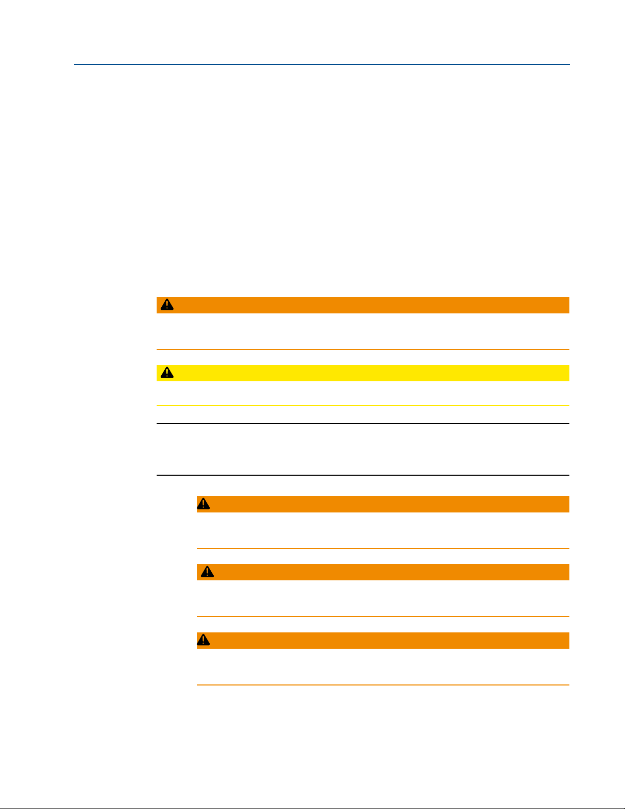
Safety notices are presented as follows:
WARNING:
Alerts user of potential danger; failure to follow the warning notice could result in serious
personal injury or death.
Section 1: Introduction and Safety Information
April 2013
CAUTION:
Identies precautions the user must take to avoid personal injury or equipment damage.
NOTE:
Highlights information critical to the user’s understanding of the 2000HP valve actuator
installation or operation.
WARNING:
Read this manual in its entirety before installing, operating, or performing
maintenance on the 2000HP actuator.
WARNING:
Use caution when working on, with, or around valves and actuators. High
pressures, forces, voltages and flammable media can be present.
WARNING:
Failure to follow instructions for proper electrical wiring, storage, setup, and
maintenance may cause serious injury, damage equipment, or void warranty.
Introduction and Safety Information
1

Section 1: Introduction and Safety Information
April 2013
WARNING:
If the actuator is being installed within a hazardous area, take into account that:
• Improper installation in hazardous areas can cause an explosion.
• Assembly, disassembly and maintenance are only allowed at the actuator
when, at the time of the activity, an explosive mixture is not present.
Installation, Operation and Maintenance Manual
Part Number: E8K-400-0413
2
Introduction and Safety Information

Installation, Operation and Maintenance Manual
Part Number: E8K-400-0413
Section 2: Storage Instructions
If your actuator cannot be installed immediately, the following procedures are to be followed.
This will ensure optimum performance from your 2000HP actuator.
Failure to comply with recommended procedures could lead to actuator malfunction and will
void the warranty.
The 2000HP actuator is an inherently weatherproof unit when shipped from the factory,
providing that all compartment covers and entry plugs remain intact. The actuator should
be immediately stored in a clean, dry warehouse, free from vibration and rapid temperature
changes, until it can be installed and commissioned.
If the actuator must be stored outside, it should be stored off of the ground, at an elevation
sufcient to prevent it from being immersed in water or buried in snow, and covered to prevent
damage from site debris.
If not attached to a valve, the preferred orientation is with the motor and control compartment
horizontal.
Section 2: Storage Instructions
April 2013
If the actuator is mounted on a valve and the valve stem protrudes from the unit, a suitable
stem protector must be installed to prevent drive sleeve corrosion. Stem protectors may be
purchased from your local EIM distributor.
CAUTION:
Condensation or moisture that enters the actuator can damage internal components, which
may ultimately result in failures.
(1) Ensure integrity of gaskets and O-rings.
(2) Seal all conduit openings, whether used or not.
(3) Replace any plastic conduit plugs with pipe plugs appropriate for the application.
(4) Place a packet of dessicant in the control housing to absorb excessive moisture.
For storage procedures exceeding one year, contact your local EIM representative for
recommendations.
Contact information is located on the last page of this manual.
Storage Instructions
3

Section 3: Product Data
April 2013
Section 3: Product Data
The EIM 2000HP pneumatic actuator from Emerson is a multi-turn air driven actuator that
is perfect for applications using linear stem, rising stem or rotating stem valves. It can be
powered by air, nitrogen, or natural gas at pressures between 400 and 1480 psi. Manual
controls and/or a number of remote pneumatic or electric control options can be provided as
shown in the table below.
Table 1. Standard Control Diagrams
Typ e Description Diagram
Manual
Pneumatic
Electric
No Controls PD-200
Local 2-Way PD-201
Fail Close PD-202
Fail Open PD-203
Double Acting PD-204
Fail Close PD-205
Fail Open PD-206
Double Acting PD-207
Installation, Operation and Maintenance Manual
Part Number: E8K-400-0413
There is a ve digit alpha-numeric code used to describe basic actuator features for computer
assisted order entry. This number appears on the actuator nameplate afxed to the actuator
gear housing. The most signicant designators for a sample 2TLG-AF actuator are shown
below.
2 T L G - A F
Frame Size Motor Size Motor Gears Worm Gears Control System Special Services
1 = 1000 T = 1500/1.0” (25mm) A = No controls
2 = 2000 U = 1500/1.5” (38mm) B = Local Manual
3 = 3000 V = 1500/2.0” (51mm) C = Remote
4 = 4000 W= 2500/2.5” (64mm)
The 2000HP is based on the proven EIM Series 2000 platform and shares many of its distinctive
features and benets such as direct mounting and handwheel operation during power loss or
emergency situations.
The four most common frame sizes of EIM actuators, the 1000, 2000, 3000 and 4000, establish
the foundation for the 2000HP. Subsequently, most major 2000HP mechanical components
are interchangeable with standard EIM electric actuators, which facilitates the acquisition of
spare parts.
The control housing is also a shared EIM electric component, resulting in NEMA 4, 4X and IEC
IP66 product ratings for the 2000HP. Working temperature range is listed at -20 / +150°F
(-29 / +66°C).
4
Product Data

Installation, Operation and Maintenance Manual
Part Number: E8K-400-0413
Section 4: Lubrication and Maintenance
Section 4: Lubrication and Maintenance
An annual check of the following items should be made of your EIM 2000HP actuator.
1. Check for any external leaks and tighten ttings appropriately and/or replace failed
components.
2. Check for internal component leakage by testing for the presence of air exiting the
exhaust port(s) while the actuator is not moving.
3. Open the control housing to inspect and tighten any loose connections.
4. Visually inspect for any mechanical damage. Replace worn or damaged components.
5. Replace any seals that permit oil leakage or water ingress.
6. Lubrication consistency and quantity needs to be checked only after 3000 cycles
unless the actuator has been leaking oil or making excessive noise. Fill or replace with
recommended uid if required .
Lubrication – EIM actuator gear housings are factory lled with a high quality lubricant carefully
selected to ensure proper performance under specied operating conditions. Refer to EIM JOB
SPEC SHEET to identify the lubricant provided. Normal operation may not require lubricant
replacement.
April 2013
Lubricant level in the gear housing should be maintained at the following quantity. Do not
overfill.
See “product data” section of this manual for determining frame size.
• 1000 and 2000 Frame Sizes
— Oil: 54 oz (1.54 Liters). Oil is recommended for all drive sleeve speeds over
51 RPM.
— Grease: 3.5 lbs (1.58 Kg.). Grease is adequate for drive sleeve speeds under
51 RPM.
• 3000 Frame Size
— Oil: 62 oz (1.83 Liters). Grease is not recommended for use in the 3000 Frame
Size
• 4000 Frame Size
— Oil: 75 oz (2.21 Liters). Grease is not recommended for use in the 4000 Frame
Size.
Lubrication and Maintenance
5

Section 4: Lubrication and Maintenance
April 2013
The following recommended lubricants are manufactured by Schaeffer Manufacturing
Company, but may be replaced with equivalent products manufactured by other reputable
companies. Lubricant selection must be made based upon ambient temperature and
application.
Table 2. Schaeffer Manufacturing Cpmpany Lubricants / Temperature for EIM
Products
Product Continuous Operating Range Part Number
#158 (ISO 68) Low Temp Oil -65 / +400°F (-54 / 204°C) 3000100228
#267 EIM Std. Oil -20 / +350°F (-29 / 177°C) 3000100227
#229 EIM Std. Grease -25 / +350°F (-32 / 177°C) 3000100222
#200 SUG (Special for EIM) -40 / +400°F (-40 / 204°C) 3000100212
#197 Low Temp, Grease -60 / +500°F (-51 / 260°C) 3000100219
#271 Food Grade -15 / +500°F (-26 / 260°C) 3000100216
#276 Food Grade Oil -15 / +300°F (-26 / 149°C) 3000100218
#286 High Temp *Na / +900°F (*Na / 482°C) 3000100220
#167 (Gear Oil) 75-140 Wt. -50 / +350°F (-45 / 177°C) 3000100230
#238 EP 1 Grease -10 / +350°F (-23 / 177°C) 3000100226
Installation, Operation and Maintenance Manual
Part Number: E8K-400-0413
NOTE:
During operation of this actuator, gear housing temperature increase in combination with
variations of outdoor temperature may cause a small pressure build-up within the actuator gear
box. EIM furnishes Pressure Relief Vent Fitting Part No. 83385 to prevent excessive pressure
build-up. Pressure Relief Vent Fitting placement on the actuator can be determined after eld
location and position of the valve have been determined. Select the highest 1/2NPT vent
location of the actuator gear box; remove the ½ NPT plug and replace with Part No. 83385.
6
Lubrication and Maintenance

Installation, Operation and Maintenance Manual
Part Number: E8K-400-0413
Section 5: Component Identification
Section 5: Component Identication
Double Pilot
Block
Pilot Gas
Filter
April 2013
½ NPT Power Gas
Connection
Directional
Control Valve
Power Gas
Pressure Gauge
Gas Motor
¾ NPT
Exhaust Port
Low Pressure
Control Housing
Component Identification
Pressure Regulator
Set at 100 psi
7
 Loading...