

EIM HQ Series, HQ-200, HQ-015, HQ-120, HQ-300 Installation & Maintenance Manual
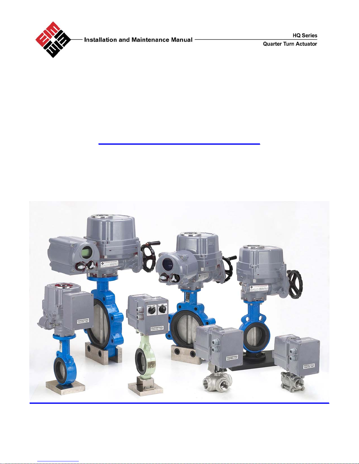
HQ Series ¼ Turn Actuator
HQ-015 thru HQ-300
IInnssttaallllaattiioonn && MMaaiinntteennaannccee MMaannuuaall
HQ Series I&M Manual HQ-400-1005 1
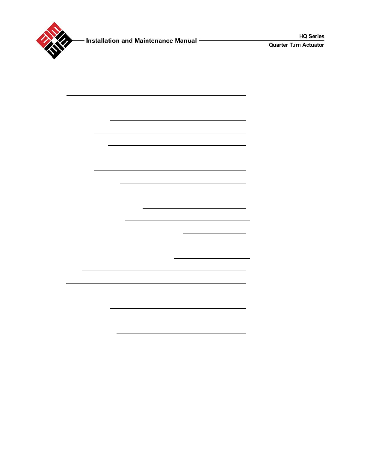
Table of Contents:
General 1.0
Actuator Mounting 2.0
External Construction 3.0
Wiring Diagrams 4.0
Power Requirements 5.0
Duty Cycle
Manual Override
6.0
7.0
Mechanical Travel Stops 8.0
Electrical Connection 9.0
Limit Switch Setting Instructions 10.0
Torque Switch Adjustment 11.0
Reverse Acting (Counter Clockwise to close) 12.0
Lubrication 13.0
MDPI (Mechanical Dial Position Indicator) 14.0
Maintenance 15.0
Storage 16.0
Mounting Base Details 18.0
Drive Bushing Details
19.0
Trouble Shooting 20.0
Standard Specifications
EIM Office Locations
HQ Series I&M Manual HQ-400-1005 2
21.0
22.0

1.0 General
HQ series electric actuators are design to provide reliable and efficient operation of 90 degree quarter turn
valves, dampers, etc
Pre-Installation Inspection
.
Warning: Use caution when working in, with, or around valves and
actuators. High pressures, forces, voltages and flammable media can be
present
Warning: Failure to follow instructions for proper electrical wiring, storage,
set-up and maintenance may cause serious injury, damage equipment, or
void warranty.
Verify the actuator nameplate to insure correct model number, torque, operating speed, voltage
and enclosure type before installation or use.
It is important to verify that the output torque of the actuator is appropriate for the torque
requirements of the valve and that the actuator duty cycle is appropriate of the intended application
2.0 Actuator Mounting
Do not lift the actuator by the handwheel
The actuator may be mounted in any position
The HQ- Series actuators are supplied with a female drive output. ISO5211. Bolt patterns are provided for
actuator mounting. The actuator drive bush is removable for ease of machining.
It is mandatory that the actuator be firmly secured to a sturdy mounting bracket or directly mounted to the
valve’s ISO mounting pad. High tensile bolts or studs with spring locking washers must be used.
The valve output shaft must be in line with the actuator output drive to avoid side-loading the shaft.
To prevent backlash, no flexibility in the mounting bracket or mounting should be allowed.
HQ Series I&M Manual HQ-400-1005 3
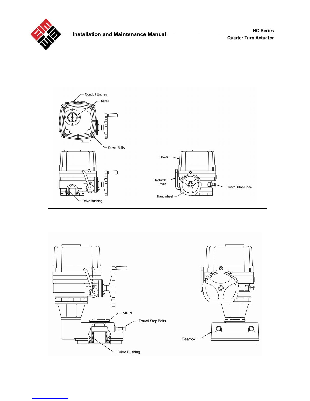
3.0 External Construction
HQ-008 ~ HQ-120
HQ-200 ~ HQ-300
HQ Series I&M Manual HQ-400-1005 4
 Loading...