


EIM 2000 Series M2CP Digital Futronic
User Manual
84829 Rev. D
March 2013


User Manual
84829 Rev. D
Table of Contents
Section 1: Introduction ���������������������������������������������������������1
Section 2: Features and Specifications �����������������������������������2
Section 3: Installation and Wiring �����������������������������������������3
Section 4: Module Setup and Calibration �������������������������������5
4.1 Indicator Lights ............................................................................................. 5
4.1.1 LED 1 .................................................................................................. 5
4.1.2 LED 2 .................................................................................................. 5
4.2 Setup ............................................................................................................ 6
4.2.1 Normal Run Mode (S1, S2, S3 OFF) ..................................................... 6
4.2.2 Cal Analog Input (S1 ON) .................................................................... 6
4.2.3 Cal Analog Output Zero (S2 ON) ......................................................... 6
4.2.4 Cal Analog Output Span (S3 ON) ........................................................ 6
4.2.5 Set Modulation Delay (S1, S2 ON) ....................................................... 7
4.2.6 Set Default Position (S2 & S3 ON) ....................................................... 7
4.2.7 Invert Analog I/O (S1, S2 & S3 ON) ...................................................... 7
4.3 Mode ............................................................................................................ 8
4.4 Calibration Procedures .................................................................................. 9
4.4.1 Calibrate Analog Input (Position Command Signal) ............................ 9
4.4.2 Calibrate Analog Output (Position Feedback) ..................................... 9
4.4.3 Select Modulation Delay Time ............................................................ 9
Table of Contents
March 2013
Appendix A: Definitions ������������������������������������������������������10
Table of Contents
I

Section 1: Introduction
March 2013
Section 1: Introduction
The Digital Futronic module uses the latest integrated microcontroller technology to
enable one electronics module to perform valve actuator modulating and positioning
control from analog control signals. The control module uses EIM’s M2CP TBM01
termination panel for interface of all analog control types. The Digital Futronic module
converts 4-20mA analog input to digital for processing and from digital to 4-20mA analog
output for position feedback. The Digital Futronic module controls three EIM motor
control starter types.
1. Futronic II Electro-mechanical AC motor starter
2. Futronic III SCR Solid-state DC motor starter
3. Futronic IV Triac Solid-state (SSR) AC motor starter
User Manual
84829 Rev. D
1
Introduction

User Manual
84829 Rev. D March 2013
Section 2: Features and Specifications
Section 2: Features and Specications
• Integral auto-tuning PID control maximizes accuracy without any user adjustments.
• Digital microcontroller adapts to any actuator and valve size, speed/stroke-time,
process pressure, etc. by automatically tuning controls to obtain maximum
accuracy without any user adjustments for bandwidth, delay time, etc.
• Automatic calibration of position input to valve travel limits.
• Built-in protection for motor and motor controls.
• DC motor speed control for Futronic III.
• Easy setup and calibration to user’s external analog control signal input and analog
feedback output. All setup and calibration adjustments by on-board DIP switches
and two miniature push buttons.
• LED indicators for normal/fault operating conditions, setup mode, loss of analog
signal, and solid-state motor control output.
• Isolated Analog Input: 4-20mA with 12-bit (.025%) resolution (calibration range
of 0-24mA). 210 Ohms input resistance. Operates from 10V to 32V loop supply.
Allows up to 750 Ohms loop resistance at 24V.
• Isolated Analog Output: 4-20mA with 16-bit (.0015%) resolution (calibration
range of 0-24mA). Drive loop resistance up to 750 Ohms. True current source with
internal 24VDC power supply. No external power source required to power loop.
Internal automatic resetting fuse for 24VDC power supply.
• Isolation dielectric strength: 2500V AC for 1 Minute (Input to output and I/O to
ground).
• Inverted Analog I/O Option: where 20mA = close valve position and 4mA = open
valve position.
• Go To Default Position Option: On loss of control signal, user selected default valve
position anywhere between 0 and 100%.
• Control Accuracy:
— Futronic II mode +/- 1.0% @ 15 second stroke time or greater
— Futronic III mode +/- 0.25% @ 15 second stroke time or greater
— Futronic IV mode +/- 0.5% @ 15 second stroke time or greater
• Nonlinearity: <0.05% of calibrated analog input and output over full range of 0-100%.
• Operating Temperature Range: -40C to +85C (-40F to +185F),
Humidity: 10% - 95% (Non-condensate)
Features and Specifications
2

Section 3: Installation and Wiring
March 2013
Section 3: Installation and Wiring
Refer to the wiring diagram supplied with the actuator for wiring details and options
supplied with the system. Figure 1 below is generic and provided primarily for wiring
4-20mA analog input and output signals. Refer to Figure 1 for proper wiring of analog
I/O and associated polarities relative to external equipment and power supplies.
Use the following rules when wiring analog I/O signals.
1. Route analog I/O cables into actuator enclosure through separate conduit entries
from power wiring.
2. Always use twisted-pair instrumentation cable for wiring 4-20mA analog input
and output signals.
3. Use shielded cable when analog signals are being installed in or routed through
high noise areas.
4. If shielded cable is used, earth ground the shield by connecting only one end of
the shield to earth.
5. Instruments or control equipment must source current to the analog input of the
Digital Futronic.
6. Remote current source to analog input must have own power source, or an
external supply is required.
7. Do not connect an external power source to the 4-20mA analog output of the
Digital Futronic module.
8. The Digital Futronic module contains its own internal 24VDC power supply for the
4-20mA output and sources current to external instruments or control equipment.
User Manual
84829 Rev. D
Figure 1 TBM01 Futronic Wiring
3
Installation and Wiring

User Manual
Section 3: Installation and Wiring
84829 Rev. D March 2013
Important Notice:
Jumper J8 located on the bottom of TBM01 must be in the 24V positionbefore the Digital
Futronic card will operate.
Installation and Wiring
4

Section 4: Module Setup and Calibration
March 2013
User Manual
Section 4: Module Setup and Calibration
DIP Switch SW3 has 6 switches designated as S1-S6 for calibration and mode selection as
summarized below. There are two push buttons labeled UP and DOWN.
Refer to Figure 2 for location of DIP switches and push buttons.
Figure 2
84829 Rev. D
4�1 Indicator Lights
4.1.1 LED 1
• Slow Flash = Normal Operating Mode.
• Rapid Flash = Setup mode (any one of switches S1 through S3 are on).
• Alternating Between Slow and Rapid Flash = Lost Analog Input (Command) Signal.
• Steady On or Steady Off = Module failure.
4.1.2 LED 2
• On when Solid State Relay (SSR or SCR) is On (control power applied to output).
5
Module Setup and Calibration

User Manual
84829 Rev. D March 2013
Section 4: Module Setup and Calibration
4�2 Setup
4.2.1 Normal Run Mode (S1, S2, S3 OFF)
Turn off S1, S2 & S3 for Normal Run Mode - Figure 3.
Figure 3
4.2.2 Cal Analog Input (S1 ON)
Press UP to set Span (20mA) Input - Figure 4.
Press DOWN button to set Zero (4mA) Input - Figure 4.
Figure 4
4.2.3 Cal Analog Output Zero (S2 ON)
Press UP to increase (4mA) Output - Figure 5.
Press DOWN to decrease (4mA) Output - Figure 5.
Figure 5
4.2.4 Cal Analog Output Span (S3 ON)
Press UP to increase (20mA) Output - Figure 6.
Press DOWN to decrease (20mA) Output - FIgure 6.
Figure 6
Module Setup and Calibration
6

Section 4: Module Setup and Calibration
March 2013
4.2.5 Set Modulation Delay (S1, S2 ON)
Press UP to select 3-Ph motor (delay = 2 sec) - Figure 7.
Press DOWN to select 1-Ph motor (delay = 12 sec) - Figure 7.
Figure 7
4.2.6 Set Default Position (S2 & S3 ON)
Press UP or DOWN to accept current valve position as default position - Figure 8.
Figure 8
User Manual
84829 Rev. D
4.2.7 Invert Analog I/O (S1, S2 & S3 ON)
Press UP to Select Inverted Mode - Figure 9.
Press DOWN to Disable Inverted Mode - Figure 9.
Figure 9
7
Module Setup and Calibration
User Manual
84829 Rev. D March 2013
Section 4: Module Setup and Calibration
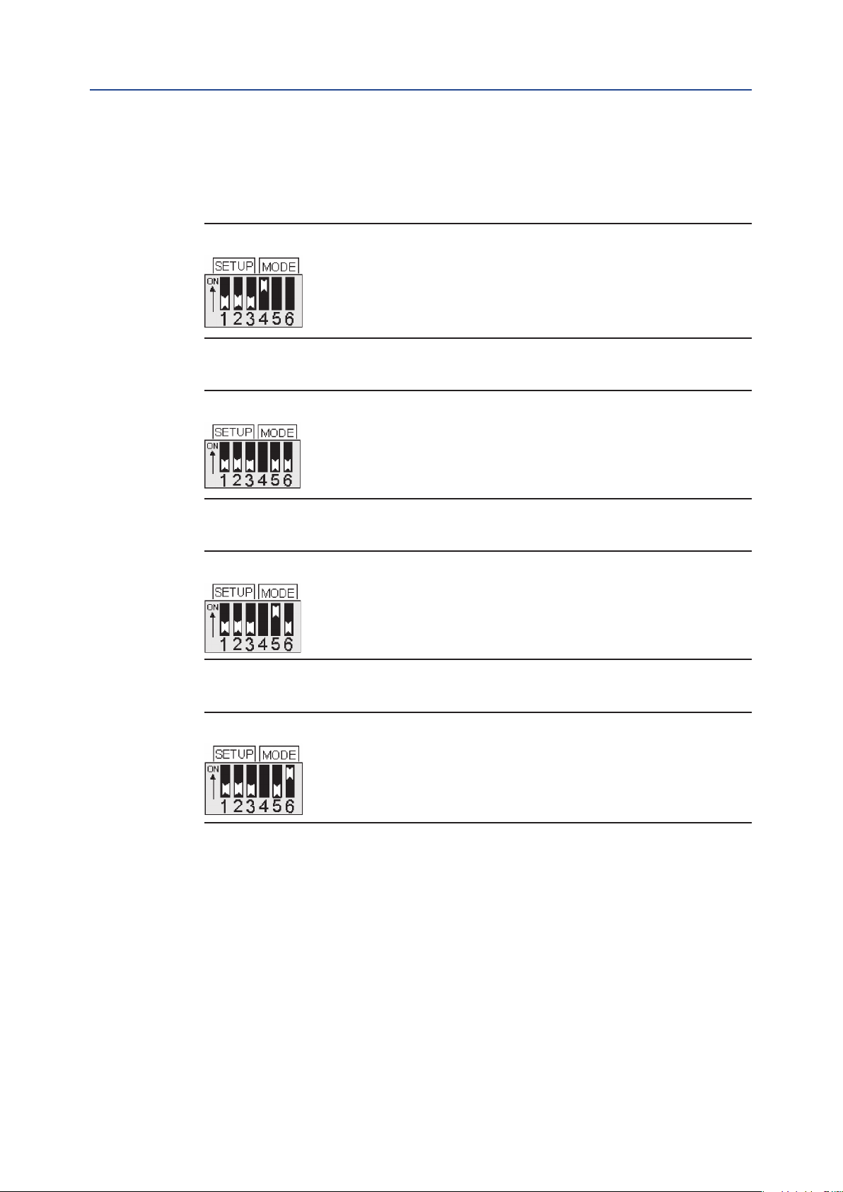
4�3 Mode
1. S4 ON = Go to Default Position on loss of analog input control signal - Figure 10.
S4 OFF = Stay put on loss of analog input control signal - Figure 10.
Figure 10
2. S5 OFF and S6 OFF > Select Futronic II mode
(Electromechanical motor starter) - Figure 11.
Figure 11
3. S5 ON and S6 OFF > Select Futronic III mode
(SCR solid-state DC motor starter) - Figure 12.
Figure 12
4. S5 OFF and S6 ON > Select Futronic IV mode
(Triac solid-state (SSR) motorstarter) - Figure 13.
Figure 13
Module Setup and Calibration
8

Section 4: Module Setup and Calibration
March 2013
User Manual
84829 Rev. D
4�4 Calibration Procedures
CAUTION
Place selector switch in “OFF” position before calibrating actuator.
4.4.1 Calibrate Analog Input (Position Command Signal)
1. Connect 4-20mA calibration source to TBM Terminals 52 (-) and 53 (+).
2. Set S1 to ON (up) position. Apply 4mA zero calibration signal and then
press DOWN push button.
3. Apply 20mA full-scale (span) calibration signal and then press UP push button.
4. Return S1 to OFF (down) position.
NOTE:
When S1 is ON, the analog input signal is fed to the analog output. A current meter may be
connect to TBM terminals 50(-) and 51(+) to monitor the analog input at the output.
4.4.2 Calibrate Analog Output (Position Feedback)
1. Connect calibrated 4-20mA meter to TBM Terminals 50 (-) and 51 (+).
2. Set S2 to ON (up) position.
3. Press UP or DOWN push button to increase or decrease zero (4mA) analog output signal.
4. Return S2 to OFF (down) position.
5. Set S3 to ON (up) position.
6. Press UP or DOWN push button to increase or decrease full-scale (20mA) analog signal.
7. Return S3 to OFF (down) position.
4.4.3 Select Modulation Delay Time
1. Set S1 and S2 to ON (up) position.
2. Press UP push button to select 3-Phase motor (Modulation delay = 2 seconds).
3. Press DOWN push button to select 1-Phase motor
(Modulation delay = 12 seconds).
4. Return S1 and S2 to OFF (down) position.
9
Module Setup and Calibration

User Manual
84829 Rev. D March 2013
Appendix
Appendix A: Denitions
1. Command = 4-20mA analog input position command signal generated by remote
control equipment. Same as position command setpoint. Zero and Full-scale
calibrated by user.
2. Position = 0-5V valve position analog input signal generated by Hall-effect
Position Sensor (HPS). Zero and Full-scale automatically calibrated by controller
based on LSC and LSO valve travel limit switches.
3. Feedback = 4-20mA analog output signal for feedback of valve position to remote
control equipment. Zero and Full-scale calibrated by user.
4. Invert = Inverted calibration of 4-20mA command where close position = 20mA,
and open position = 4mA. Feedback is also inverted.
5. Deadband = Allowable error tolerance to keep valve stopped, i.e. do not turn
on motor control outputs. Deadband cannot be adjusted by the user. Deadband
has a beginning default value based on selected operating mode (motor starter type)
and then controller automatically adjusts the deadband to obtain the best accuracy.
Default deadband based on motor starter type:
a. Futronic II = +/-1.0% deadband
b. Futronic III = +/-0.25% deadband
c. Futronic IV = +/-0.50% deadband
6. Error = Difference between Command and Position.
Error = Command-Position
If not Invert and Error = Positive then open valve
If not Invert and Error = Negative then close valve
If Invert and Error = Positive then close valve
If Invert and Error = Negative then open valve
7. Nonlinearity = Difference between analog input and analog output at current
valve position over the full valve operating range.
8. Close Coast = Difference between Position when the motor is turned off and
Position when the valve stops moving in the close direction. Coast is caused by
both inertia of the motor and latency of Position update due to analog input
ltering. The controller measures close coast to automatically tune control for
maximum accuracy.
9. Open Coast = Difference between Position when the motor is turned off and
Position when the valve stops moving in the open direction. The controller
measures open coast to automatically tune control for maximum accuracy.
10. Modulation Delay = Time between when the motor is turned off until the
motor can be started again. This delay prevents excessive number of starts of the
motor, preventing overheating the motor and premature burnout of the reversing
contactor. Modulation delay also prevents valve plugging when the actuator
reverses direction. If a three phase motor is used, the delay time is 2 seconds or
1800 starts per hour. If a single phase, capacitor start, AC motor is used, then the
delay is 12 seconds or 300 starts per hour. The delay between motor control pulses
while the valve is being jogged to position is automatically reduced to one second.
Appendix
10

Appendix
March 2013
User Manual
84829 Rev. D
11. Turn-off Delay = 10 Seconds = Delay after motor stops before turning off Openor
Close reversing contactor outputs unless a reversal in direction is required.
If reversal in direction, then Modulation Delay time is used. Valid only when
Futronic III or Futronic IV modes are selected. This delay prevents excessive
operation of the contactor while modulating or the 4-20mA command signal is
being ramped by a PID control loop.
12. Accel = Time required to accelerate motor speed from zero to full speed when
motor is started due to Error greater than Deadband. The purpose of Accel is to
soft-start the motor and to help prevent control overshoot when making small
position changes. Accel is inversely proportional to Error and is automatically
adjusted by the controller.
13. Decel = Time required to decelerate motor speed from full speed to zero while
Position is approaching Command position setpoint. Valid only when Futronic
III or Futronic IV modes are selected. Decel is proportional to Error. If motor is
at full speed (Accel time expired) and Error is less than tuned parameter then
the controller begins decelerating motor speed over a period of time where
Decel=(Error-Deadband)*T Sec. Decel is activated only when Accel time has
expired. This prevents motor stall when making small position changes.
If Error is less than Deadband then Decel=0.
14. DC Motor Speed Control = Full speed of the motor is set at the factory using
a potentiometer on the SCR motor control module. The Digital Futronic module
regulates full speed of the motor, maintaining accurate speed/valve travel time
regardless of high or low power line conditions and varying load conditions. Valid
only for Futronic III.
11
Appendix


World Area Configuration Centers (WACC) offer sales support, service,
inventory and commissioning to our global customers.
Choose the WACC or sales office nearest you:
NORTH & SOUTH AMERICA
19200 Northwest Freeway
Houston TX 77065
USA
T +1 281 477 4100
F +1 281 477 2809
Av. Hollingsworth
325 Iporanga Sorocaba
SP 18087-105
Brazil
T +55 15 3238 3788
MIDDLE EAST & AFRICA
P. O. Box 17033
Dubai
United Arab Emirates
T +971 4 811 8100
F +971 4 886 5465
P. O. Box 10305
Jubail 31961
Saudi Arabia
T +966 3 340 8650
F +966 3 340 8790
F +55 15 3228 3300
24 Angus Crescent
ASIA PACIFIC
Longmeadow Business Estate East
P.O. Box 6908 Greenstone
No. 9 Gul Road
#01-02 Singapore 629361
T +65 6777 8211
F +65 6268 0028
No. 1 Lai Yuan Road
1616 Modderfontein Extension 5
South Africa
T +27 11 451 3700
F +27 11 451 3800
EUROPE
Wuqing Development Area
Tianjin 301700
P. R. China
T +86 22 8212 3300
F +86 22 8212 3308
Berenyi u. 72- 100
Videoton Industry Park
Building #230
Székesfehérvár 8000
Hungary
T +36 22 53 09 50
F +36 22 54 37 00
For complete list of sales and manufacturing sites, please visit
www.emerson.com/actuationtechnologieslocations or contact us at
info.actuationtechnologies@emerson.com
www.emerson.com/eim
©2017 Emerson. All rights reserved.
The Emerson logo is a trademark and service mark of Emerson Electric Co.
TM
is a mark of one of the Emerson family of companies.
EIM
All other marks are property of their respective owners.
The contents of this publication are presented for information purposes
only, and while every effort has been made to ensure their accuracy,
they are not to be construed as warranties or guarantees, express or
implied, regarding the products or services described herein or their use
or applicability. All sales are governed by our terms and conditions, which
are available on request. We reserve the right to modify or improve the
designs or specifications of our products at any time without notice.
 Loading...