

Page 1

DCMlink Software
Quick Start Guide
DCM-401-0918 Rev. 2.4
November 2020
Page 2

Notes
November 2020
Quick Start Guide
DCM-401-0918 Rev. 2.4
This page is intentionally left blank
Page 3

Quick Start Guide
DCM-401-0918 Rev. 2.4
Table of Contents
Section 1: Installing DCMlink
1.1 Installation Overview .................................................................................... 1
1.2 New Installation ............................................................................................ 1
1.3 DCMlink Auto Update ................................................................................... 6
Section 2: License Activation Wizard
2.1 License Features ............................................................................................ 8
2.2 Obtaining Your License .................................................................................. 9
2.3 Activating License Key File ........................................................................... 13
2.4 Activating Temporary License ..................................................................... 16
2.5 Activate License Key for Other PC ................................................................ 20
Table of Contents
November 2020
Section 3: Setting Up DCMlink Networks
3.1 Setup Modbus Network .............................................................................. 23
3.2 Modbus TCP/IP Settings .............................................................................. 29
3.3 RDM Connection Settings ........................................................................... 30
3.4 Setup Bluetooth Network ............................................................................ 30
3.5 Setup HART Network .................................................................................. 32
3.6 Multiplexer Networks for DCMlink SNAP-ON ............................................... 48
3.7 AMS SNAP-ON Setup ................................................................................... 54
3.8 Troubleshooting Communication Issues ..................................................... 57
Table of Contents
i
Page 4

Notes
November 2020
Quick Start Guide
DCM-401-0918 Rev. 2.4
This page is intentionally left blank
Page 5

Quick Start Guide
DCM-401-0918 Rev. 2.4
Section 1: Installing DCMlink
1.1 Installation Overview
DCMlink Software should be installed on a computer that meets the system requirements.
The following steps detail how to uninstall and reinstall. Reinstall if the software is to be
removed, updated or repaired only.
1.2 New Installation
1.2.1 If the user has a previous version already installed, please uninstall it rst from the
Control Panel >Add Remove Programs. Next, please delete the DCMlink shortcut from
the Desktop.
1.2.2 Locate and then open the DCMlink.exe located in the installation folder found in the
DCMlink installer (sent to customer via web link, CD or USB media).
Section 1: Installing DCMlink
November 2020
NOTE:
Installation of DCMlink requires administrator privileges.
Figure 1 DCMlink Installer
Double Click on DCMlink Software v2.4 Installation.exe
Installing DCMlink
1
Page 6

Section 1: Installing DCMlink
November 2020
1.2.3 Click Next button.
Figure 2 DCMlink Installation Initialization
Quick Start Guide
DCM-401-0918 Rev. 2.4
Click on “Next” Button
1.2.4 There are 2 options for installation. Click on one option and then click Next.
• DCMlink SOLO
• DCMlink SNAP-ON
NOTE:
Both SOLO and SNAP-ON can be installed in one installation by selecting both options.
1.2.4.1 DCMlink SOLO
NOTE:
Install DCMlink software for stand-alone operation.
Figure 3 DCMlink SOLO Option
Click on “Next” Button
2
Installing DCMlink
Page 7

Quick Start Guide
DCM-401-0918 Rev. 2.4
Section 1: Installing DCMlink
November 2020
1.2.4.2 DCMlink SNAP-ON
NOTE:
Install DCMlink software enabled for operation as a SNAP-ON to AMS Device Manager.
AMS Device Manager must be licensed for the DCMlink SNAP-ON.
Figure 4 DCMlink SNAP-ON Option
Click on “Next” Button
1.2.5 Read Terms and Conditions and select accept and click Next.
Figure 5 Terms of Use
Read Terms and Conditions and select the options
I agree
Click Next
Installing DCMlink
3
Page 8

Section 1: Installing DCMlink
November 2020
1.2.6 Next, click Install.
Figure 6 Install DCMlink
Quick Start Guide
DCM-401-0918 Rev. 2.4
Click on “Install” Button
1.2.7 Installation will begin.
Figure 7 Installation Progress Bar
4
Installing DCMlink
Page 9

Quick Start Guide
DCM-401-0918 Rev. 2.4
1.2.8 Click Finish to complete installation.
Figure 8 Completing the Installation
Section 1: Installing DCMlink
Click on “Finish” Button to complete
the installation
November 2020
1.2.9 Start DCMlink application from desktop shortcut or from the list of All Programs.
Figure 9 DCMlink Start Menu Shortcut
Start DCMlink from dekstop shortcut or
from list of All Programs
Installing DCMlink
5
Page 10

Section 1: Installing DCMlink
November 2020
1.3 DCMlink Auto Update
1.3.1 If any new version of DCMlink is available, all users will get a notication about it. User is notied
about update on launching DCMlink application or using menu option Help->Check for Updates.
NOTE:
User with Administrative rights will only be able to launch DCMlink Updater.
1.3.2 To install DCMlink updates, click on ‘Yes’.
Figure 10 Update Notication
Quick Start Guide
DCM-401-0918 Rev. 2.4
6
Installing DCMlink
Page 11

Quick Start Guide
DCM-401-0918 Rev. 2.4
Section 1: Installing DCMlink
November 2020
1.3.3 On Launching DCMlink Updater below screen is shown, that specify the size of download,
available version, Release Note and other information. To proceed with Update user, need to
agree to “Emerson Data Privacy Policy” and Click on “Install”.
Figure 11 DCMlink Updater
Installing DCMlink
1.3.4 Once Update operation is completed. DCMlink Application gets Closed. After update if user
“Check For Update” again, below screen will be shown.
Figure 12 Latest Version Notication
7
Page 12

Section 2: License Activation Wizard
November 2020
Section 2: License Activation Wizard
2.1 License Features
Table 1. DCMlink License Features
Product Name
Feature
SOLO Standard Unlimited
Modbus Master
Modbus Slave
Modbus TCP-IP
Bluetooth
HART Modem Not Supporting
HART Multiplexer
Standard Diagnostics
(Torque Prole, Step
Response)
Standard Diagnostics
(Partial Stoke Test)
Status Monitor
Configuration
Calibration
Database with Number
of Tag s
Unlimited Unlimited Unlimited
SOLO SNAP-ON
SOLO Advanced
(Under
Development)
Quick Start Guide
DCM-401-0918 Rev. 2.4
SNAP-ON
Unlimited
Not Applicable
Not Applicable
Not Applicable
Not Applicable
8
License Activation Wizard
Page 13

Quick Start Guide
DCM-401-0918 Rev. 2.4
2.2 Obtaining Your License
2.2.1 Double click DCMlink icon. The user will be prompted to run the License Wizard and
click Yes.
Figure 13 Running License Wizard
Section 2: License Activation Wizard
November 2020
2.2.2 Next click on "Purchase SNAP-ON" button.
Figure 14 Request New License
License Activation Wizard
9
Page 14
Section 2: License Activation Wizard
November 2020
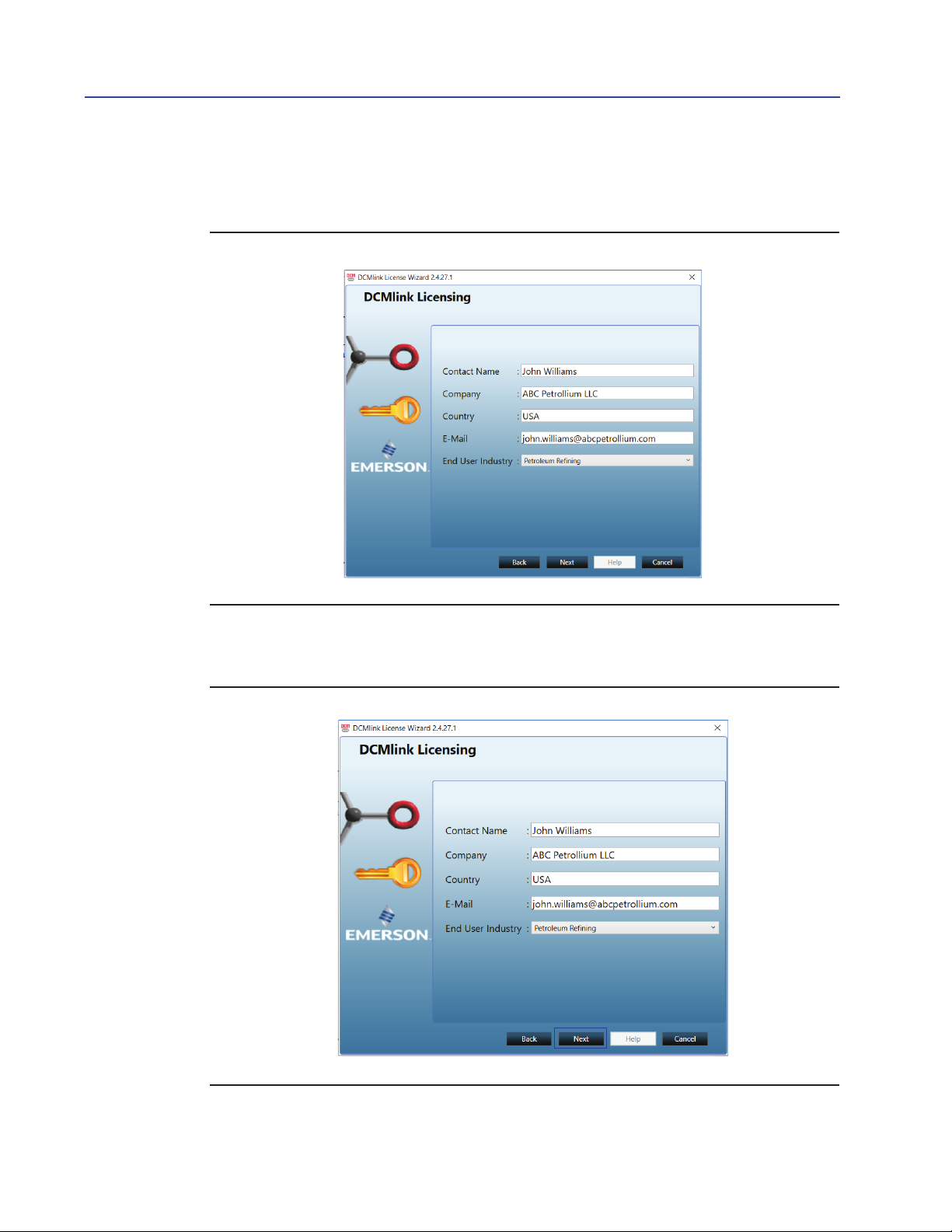
2.2.3 Enter the contact details. All elds are required. If the user does not have a fax number,
please enter telephone number. This information will be used to request a license key.
Figure 15 Input License Information
Quick Start Guide
DCM-401-0918 Rev. 2.4
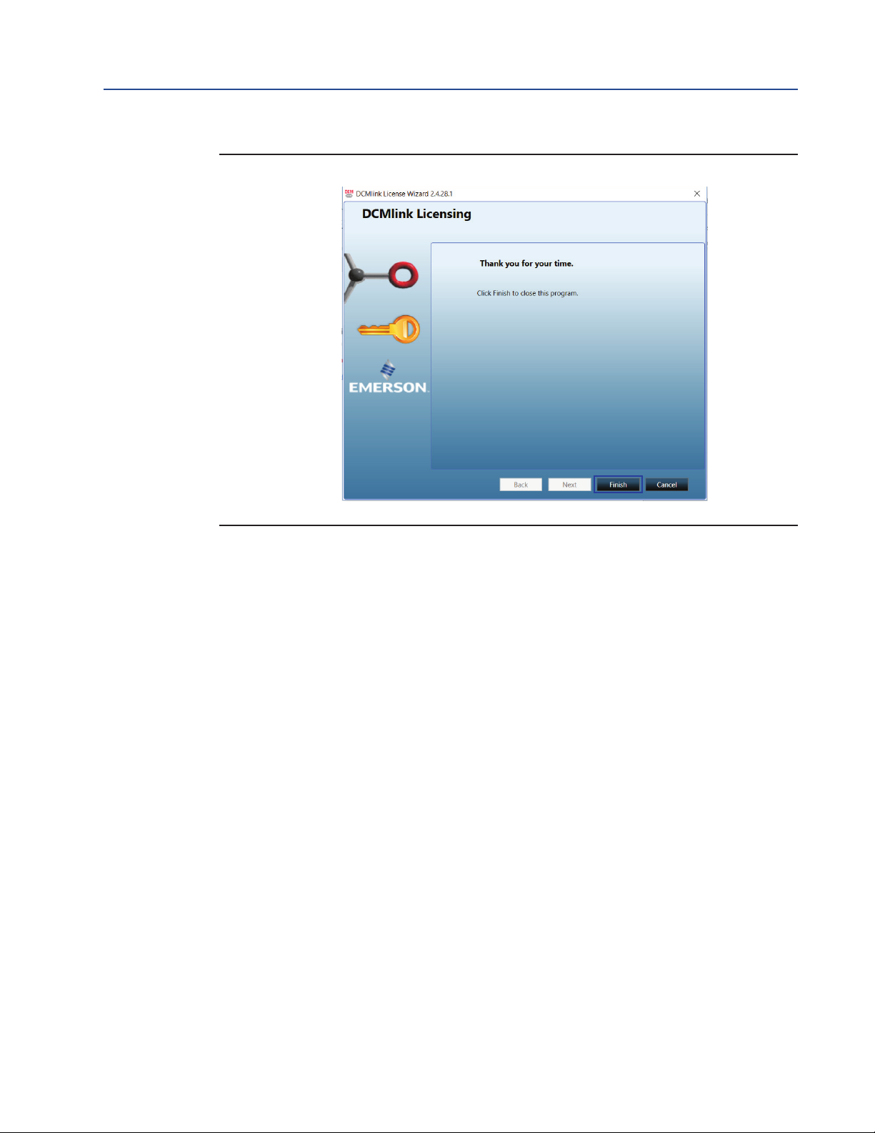
2.2.4 Select delivery method, and click Next.
Figure 16 Review License Information
10
License Activation Wizard
Page 15

Quick Start Guide
DCM-401-0918 Rev. 2.4
Section 2: License Activation Wizard
November 2020
2.2.5 Provide the serial number and REP order number (e.g. DEMO).
Figure 17 Input Serial Number / REP Order Number
2.2.6 After the registration form is completed, the information can be saved and/or printed.
Click Save to generate a license key request le. Once complete, click Next.
Figure 18 Input Received License Key
License Activation Wizard
11
Page 16

Section 2: License Activation Wizard
November 2020
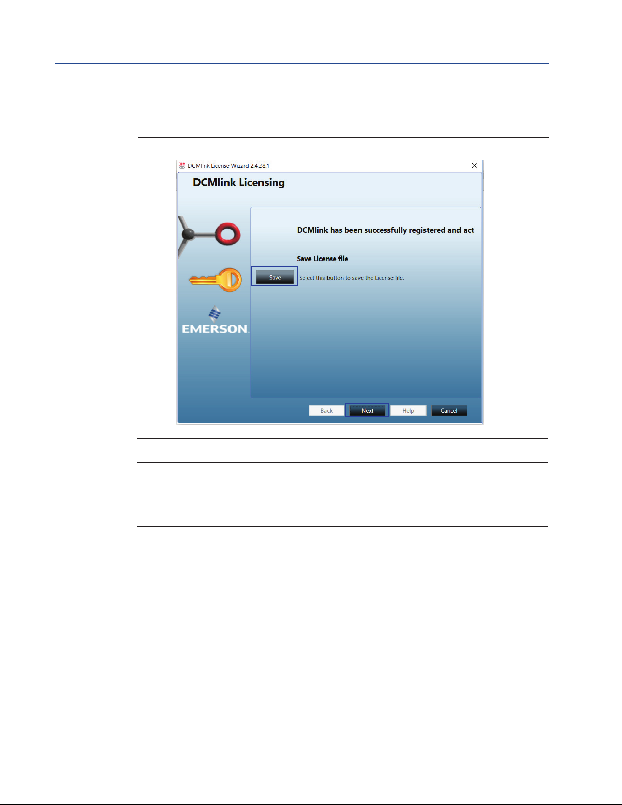
2.2.7 The license request has now been sent to the DCMlink Registration Center. Click Finish.
Figure 19 Finishing the License Key Request
Quick Start Guide
DCM-401-0918 Rev. 2.4
2.2.8 To obtain license, send license registration le to the email address mentioned in the
above screen. User can also send a scanned copy of the printed registration form or call
the number shown above to obtain the license key (please have the registration code/
le ready).
12
License Activation Wizard
Page 17

Quick Start Guide
DCM-401-0918 Rev. 2.4
2.3 Activating License Key File
2.3.1 After the user receives the license key le, please re-run the License Wizard by
double-clicking on DCMlink icon and, click Enter License Key.
Figure 20 Entering the License Key File
Section 2: License Activation Wizard
November 2020
2.3.2 Click Import from File and select the license key le with the .lic extension.
This is the license key le the user received via the DCMlink registration.
Once loaded, click Next.
Figure 21 Import Existing License Key File
License Activation Wizard
13
Page 18

Section 2: License Activation Wizard
November 2020
2.3.3 Once the license key has been imported, the installed DCMlink features will be shown
on this window. Click Next.
Figure 22 Available Features Review
Quick Start Guide
DCM-401-0918 Rev. 2.4
14
License Activation Wizard
Page 19

Quick Start Guide
DCM-401-0918 Rev. 2.4
Section 2: License Activation Wizard
November 2020
2.3.4 DCMlink is now successfully licensed. Click Finish.
Figure 23 Complete License
License Activation Wizard
15
Page 20

Section 2: License Activation Wizard
November 2020
2.4 Activating Temporary License
DCMlink allows the use of a time-limited or temporary license that permits the use of certain
software features for the duration of the license. Consult the following steps to activate this
temporary license.
NOTE:
By default, DCMlink Standard provides unlimited and SNAP-ON for 90 days trial. After the
90-day trial period, the user needs to request a permanent license for SNAP ON.
2.4.1 Click on SOLO Free/SNAP-ON Trial button and click Next.
Figure 24 Temporary license
Quick Start Guide
DCM-401-0918 Rev. 2.4
16
License Activation Wizard
Page 21

Quick Start Guide
DCM-401-0918 Rev. 2.4
Section 2: License Activation Wizard
November 2020
2.4.2 Fill all details and click on Next button.
Figure 25 Temporary License Loaded
2.4.3 Conrm all user details and agree to Emerson Data Privacy Policy.
Figure 26 Temporary License is Complete
License Activation Wizard
17
Page 22

Section 2: License Activation Wizard
November 2020
2.4.4 License Manager will try to connect with Emerson server. If Internet connectivity is
present, then Trial license is activated.
Figure 27 Trial License Activated
Quick Start Guide
DCM-401-0918 Rev. 2.4
2.4.5 If Internet connectivity is not present, then save Registration le and follow steps to
activate Trial license for Remote Computer.
Figure 28
18
License Activation Wizard
Page 23
Quick Start Guide
DCM-401-0918 Rev. 2.4
Section 2: License Activation Wizard
November 2020
Figure 29
License Activation Wizard
19
Page 24

Section 2: License Activation Wizard
November 2020
2.5 Activate License Key for Other PC
Using this option DCMlink allows to generate license key for another computer. To do so,
Internet connectivity and another computer’s Registration le is Required.
Consult the following steps to activate this temporary license.
NOTE:
To do so, this computer shall be connected to Internet.
2.5.1 Click on License for Other’s PC button and click Next.
Figure 30
Quick Start Guide
DCM-401-0918 Rev. 2.4
20
License Activation Wizard
Page 25

Quick Start Guide
DCM-401-0918 Rev. 2.4
Section 2: License Activation Wizard
November 2020
2.5.2 Upload Registration le of Computer whose license needs to be generated and click Next.
Figure 31
2.5.3 Verify all details and agree to Emerson Data privacy policy and click Next.
Figure 32
License Activation Wizard
21
Page 26
Section 2: License Activation Wizard
November 2020
2.5.4 Save trial License key and click Next.
Figure 33
Quick Start Guide
DCM-401-0918 Rev. 2.4
NOTE:
1. Carry this License le to your system.
2. To Activate the License on your system, follow all steps as mentioned in “2.3 Activating
License Key” section.
22
License Activation Wizard
Page 27
Quick Start Guide
DCM-401-0918 Rev. 2.4
Section 3: Setting Up DCMlink Networks
Section 3: Setting Up DCMlink Networks
3.1 Setup Modbus Network
NOTE:
For Modbus, there are three types of connections available. First is the Modbus Master,
second is RDM slave mode (only for TEC2000) and third one is TCP/IP (user needs CAM09/209
card). Refer to the following wiring connection to connect DCMlink to the respective actuator.
CAUTION
!
Before working on the wiring connections, power down the actuator.
November 2020
For TEC2000:
Separate Terminal Chamber (STC) contains terminal block for wiring connection. Pinch bar to
rotate the STC cover in a counter-clockwise direction, this will open the STC cover and the user
will see the terminal block in STC.
Figure 34 TEC2000 Terminal Chamber
Figure 35 Opening TEC2000 Terminal Chamber
Setting Up DCMlink Networks
23
Page 28

Section 3: Setting Up DCMlink Networks
November 2020
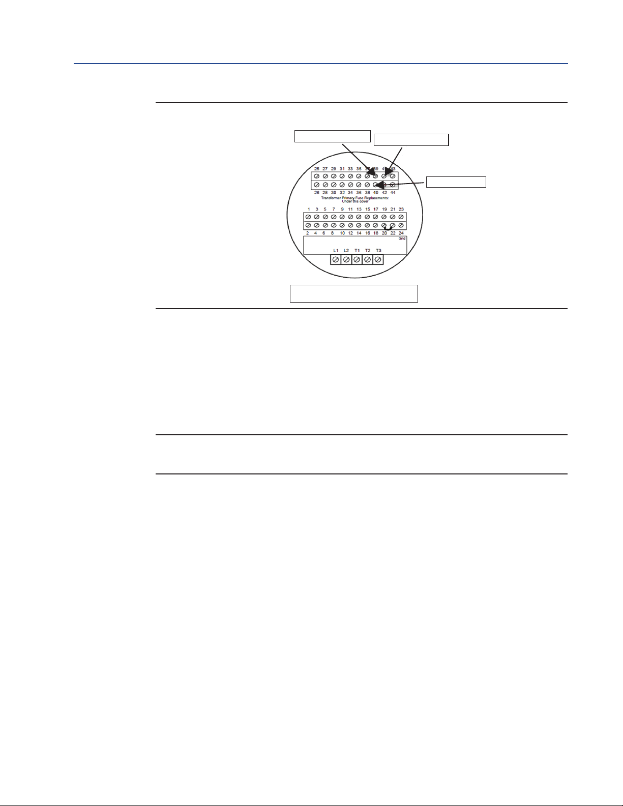
a. STC – With Terminal Block Numbering
Figure 36 Opened TEC2000 Terminal Chamber
Quick Start Guide
DCM-401-0918 Rev. 2.4
1. For TEC2:
Please refer to the following for different wiring connections:
a. For Modbus Master Mode:
– Pin 39 to +Ve of RS485
– Pin 41 to -Ve of RS485
– Pin 40 to Ground of RS485 [Optional]
NOTE:
The pins above should be used only for the CAM205 or CAM228.
For the TEC2, the recommended connection is the dedicated DCMlink port.
For more information on the pin layout, consult the TEC2 Instruction and Operation Manual.
24
Setting Up DCMlink Networks
Page 29
Quick Start Guide
DCM-401-0918 Rev. 2.4
Section 3: Setting Up DCMlink Networks
November 2020
Figure 37 Modbus Connection on STC
Pin 39 to +Ve of RS485
(TEC2 connection for "Modbus Master" Mode)
Pin 41 to -Ve of RS485
Pin 40 to Ground
STC
b. For Modbus Master Mode (Using DCMlink dedicated pins).
Another way to connect DCMlink with TEC2 is by using DCMlink dedicated
pins (36, 37, and 38). The following are the dedicated pin details:
– Pin 36 to +Ve of RS485
– Pin 38 to -Ve of RS485
– Pin 37 to Ground of RS485 [Optional]
NOTE:
For this section "b" only, connection baud rate is 115200.
c. For Modbus Master Mode on HART CAM216:
– Pin 39 to +Ve of RS485
– Pin 40 to -Ve of RS485
3.1.1 After wiring the connections with the actuator, check the serial port number on PC.
For this, right-click on My Computer and go to “Manage-> Computer Management
-> System Tools -> Device Manager-> Ports -> Communication Port (Port Number)"
Setting Up DCMlink Networks
25
Page 30
Section 3: Setting Up DCMlink Networks
25 (+Ve of RS485) 24 (-Ve of RS485)
November 2020
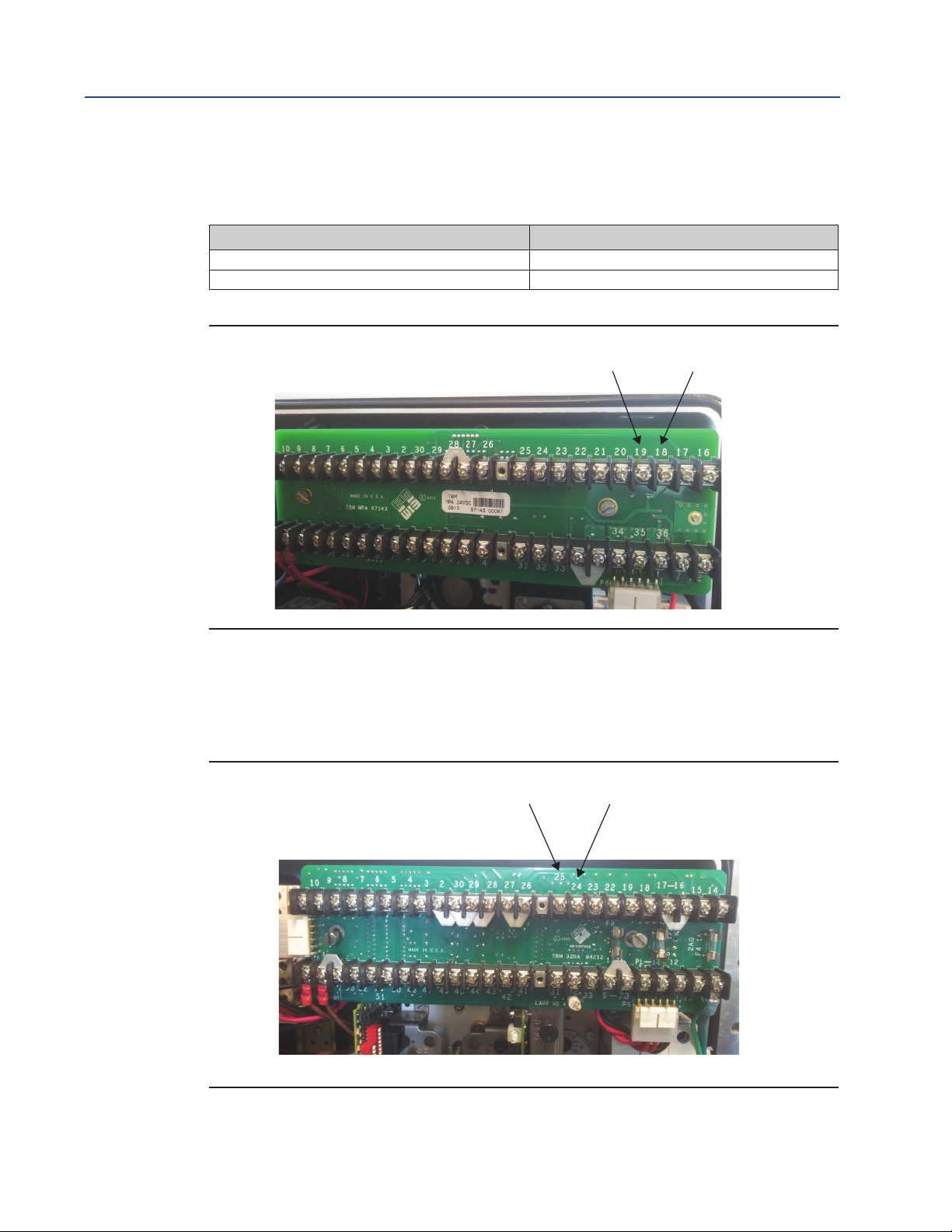
2. For MPA:
Table 2. CAM Card Pin Conguration
Without CAM05, or any other protocol CAM card With CAM05, or any other protocol CAM card
Pin 19 is +Ve of RS485 Modem Pin 25 is +Ve of RS485 Modem
Pin 18 is -Ve of RS485 Modem Pin 24 is -Ve of RS485 Modem
Figure 38 MPA Modbus Connection
Quick Start Guide
DCM-401-0918 Rev. 2.4
19 (+Ve of RS485) 18 (-Ve of RS485)
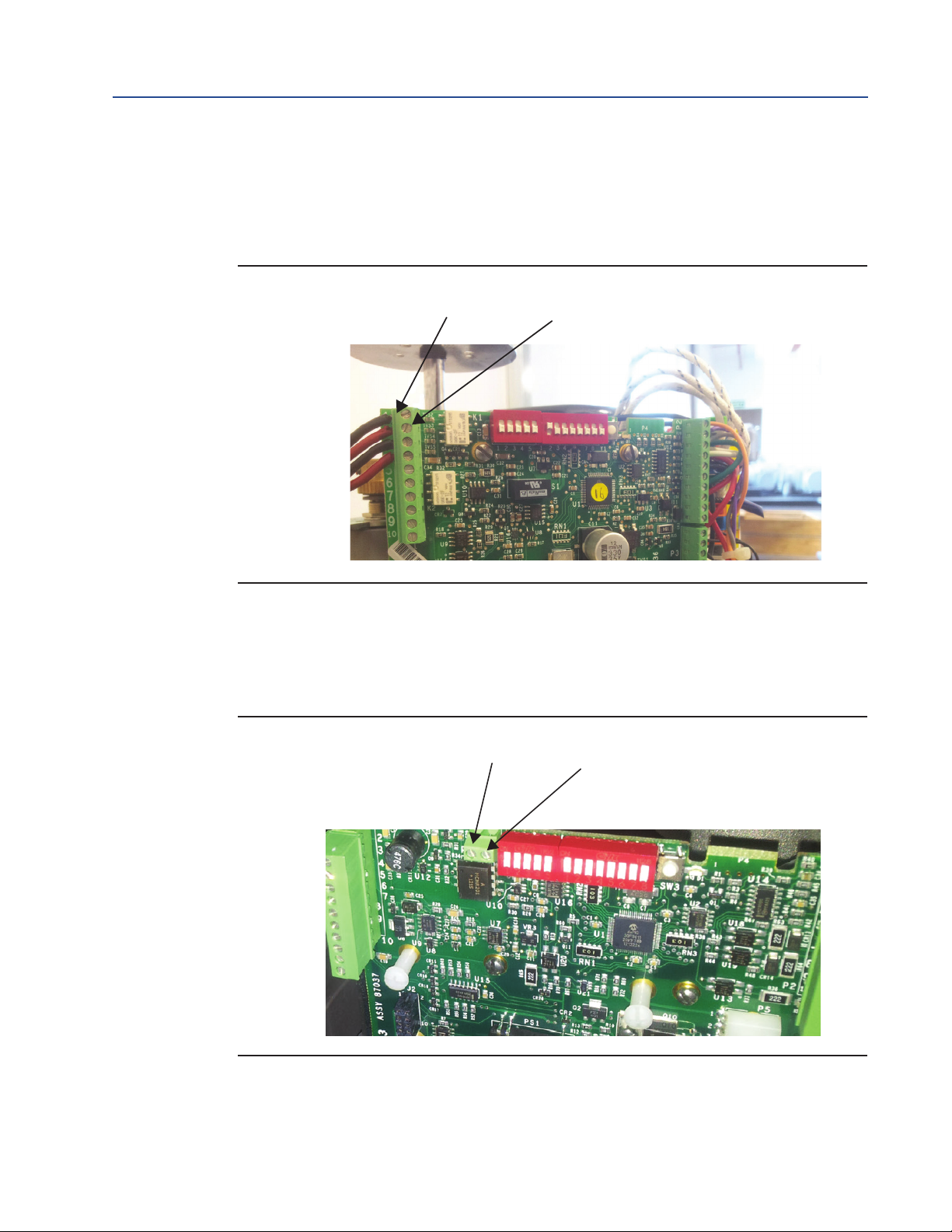
3. For M2CP:
— Pin 25 is +Ve of RS485 Modem
— Pin 24 is -Ve of RS485 Modem
Figure 39 M2CP Modbus Connection
26
Setting Up DCMlink Networks
Page 31
Quick Start Guide
1 (-Ve of RS485)
2 (+Ve of RS485)
1 (+Ve of RS485)
DCM-401-0918 Rev. 2.4
Section 3: Setting Up DCMlink Networks
November 2020
4. For HQDCM32 Series:
— Pin 1 is -Ve of RS485 Modem
— Pin 2 is +Ve of RS485 Modem
Figure 40 HQ DCM32 Modbus Connection (1)
5. For HQDCM33 Series:
— Pin 1 is +Ve of RS485 Modem
— Pin 2 is -Ve of RS485 Modem
Figure 41 HQ DCM33 Modbus Connection (2)
2 (-Ve of RS485)
Setting Up DCMlink Networks
27
Page 32

Section 3: Setting Up DCMlink Networks
November 2020
6. For EHO:
– Pin 39 to +Ve of RS485
– Pin 41 to -Ve of RS485
– Pin 40 to ground of RS485 [Optional]
Figure 42 EHO Modbus Connection
Quick Start Guide
DCM-401-0918 Rev. 2.4
Pin 39 to +Ve of RS485
(EHO connection for "Modbus Master" Mode)
STC
7. For XTE3000:
– Pin: A1+, A2- OR
– Pin: A5+, A6-
Figure 43 XTE3000 Modbus Connection
Pin 41 to -Ve of RS485
Pin 40 to Ground
28
NOTE:
For XTE3000, the user will need the Modbus Bus Card.
Setting Up DCMlink Networks
Page 33

Quick Start Guide
DCM-401-0918 Rev. 2.4
NOTE:
• COM port settings shall match with device(s)
— The Baud rate, parity, Stopbits shall match
— All devices connected to the same COM port shall use the same settings
— Use multiple COM ports incase if different settings are required
3.2 Modbus TCP/IP Settings
3.2.1 The user needs to use Modbus TCP/IP CAM card to utilize this feature.
NOTE:
For TEC2000 and TEC2, the user will need to use a CAM209 Card.
For M2CP, MPA, EHO and HQ, the user will need a CAM09 Card.
Section 3: Setting Up DCMlink Networks
November 2020
Figure 44 CAM209 Connected to TEC2000 Actuator
NOTE:
Details on the conguration of CAM09/209 is found on the document.
Setting Up DCMlink Networks
29
Page 34

Section 3: Setting Up DCMlink Networks
November 2020
3.3 RDM Connection Settings
The DCMlink fully supports the RDM mode connection with TEC2000 actuator.
3.3.1 For this, select serial COM Port number and select timeout delay as per actuator
COM Port settings.
NOTE:
RDM Slave Mode is only available for the TEC2000 actuator.
3.3.2 DCMlink works with below settings to connect with TEC2000 in RDM mode:
— STC pin numbers:
– Pin 21 to +Ve of RDM Slave Mode
– Pin 23 to -Ve of RDM Slave Mode
— Baud Rate: 9600
— Parity: None
— Stop Bits: 1
These parameters are not allowed to be modied.
Quick Start Guide
DCM-401-0918 Rev. 2.4
3.4 Setup Bluetooth Network
DCMlink allows the detection and conguration of devices connected via Bluetooth. Using the
Bluetooth device scanner in the navigation bar, the user can perform a device scan by following
the steps and screenshots shown.
NOTE:
The user needs to have Bluetooth enabled on computer to allow the use of this function.
User can check if computer has Bluetooth function enabled or not. If the bluetooth function is
not present, please consult the system administrator or IT.
30
Setting Up DCMlink Networks
Page 35

Quick Start Guide
DCM-401-0918 Rev. 2.4
Section 3: Setting Up DCMlink Networks
November 2020
3.4.1 On the navigation bar, the Bluetooth node will be populated. The name of the
Bluetooth node in DCMlink will be the same as the name of the Bluetooth at the
operating system level. The user cannot change the name of the Bluetooth name from
the DCMlink, but it is possible to change this from the operating system.
Figure 45 DCMlink Home Screen with Bluetooth
Figure 46 Scanning the Bluetooth Network
Setting Up DCMlink Networks
31
Page 36

Section 3: Setting Up DCMlink Networks
November 2020
3.5 Setup HART Network
3.5.1 Attaching HART Modem
A HART modem is a communication device that allows DCMlink to communicate with the
actuator. The following section provides necessary information for attaching the HART modem
to the computer and actuator.
NOTE:
HART modem drivers, needed for the HART modem to work, are installed during
DCMlink installation.
3.5.1.1 HART Modem Installation for DCMlink SOLO
HART modem attaches to USB port usually found on the back of the computer or the serial port.
• Locate the serial port or USB port where modem will be connected.
• Make note of the port where HART modem is attached.
• Attach HART modem directly to the serial port, USB port, or to a cable connected to
serial port or USB port.
• Use the modem cable assembly to connect HART modem to the actuator, or to
signal wiring.
• To communicate with actuator, locate the signal wires or the terminals of the actuator.
• Clip cable assembly to wires or terminals.
• Refer to document HART IOM for more information on using the HART modem.
Quick Start Guide
DCM-401-0918 Rev. 2.4
32
3.5.1.2 HART Modem Installation for DCMlink SNAP-ON
The HART modem attaches to USB port usually found on the back of the computer or the serial port.
• Locate serial port or USB port where modem will be connected.
• To configure HART modem, refer to AMS manual.
Setting Up DCMlink Networks
Page 37

Quick Start Guide
DCM-401-0918 Rev. 2.4
Section 3: Setting Up DCMlink Networks
November 2020
Steps for installing stand-alone AMS:
Before adding DD to AMS, HART Modem on AMS needs to be configured. (Ensure that HART
Modem drivers are already installed before configuring Modems on AMS). Follow steps below:
• Network Configuration:
— Open Start Menu
— Click Programs
— Click AMS Device Manager
— Click Network Configuration
Figure 47 Network Conguration
Setting Up DCMlink Networks
— Select Network Component Type and click Add.
— For HART device: HART Modem.
33
Page 38

Section 3: Setting Up DCMlink Networks
November 2020
Figure 48 Select Network Component Type
— Click Install and follow screen instructions.
Quick Start Guide
DCM-401-0918 Rev. 2.4
Figure 49 Add HART Modem Wizard-Start
34
Setting Up DCMlink Networks
Page 39

Quick Start Guide
DCM-401-0918 Rev. 2.4
Section 3: Setting Up DCMlink Networks
Figure 50 Add HART Modem Wizard-Modem Name
November 2020
Figure 51 Add HART Modem Wizard-Network Controller
Setting Up DCMlink Networks
35
Page 40

Section 3: Setting Up DCMlink Networks
November 2020
— Select one COM Port from the list.
Figure 52 Add HART Modem Wizard-Connection
Quick Start Guide
DCM-401-0918 Rev. 2.4
Figure 53 Add HART Modem Wizard-Multi Drop
36
Setting Up DCMlink Networks
Page 41

Quick Start Guide
DCM-401-0918 Rev. 2.4
— When finished HART Modem will be shown on the Network
Configuration Screen.
Figure 54 Network Conguration
Section 3: Setting Up DCMlink Networks
November 2020
3.5.2 Multiplexer Networks for DCMlink SOLO
3.5.2.1 Conguring Communications HART MUX (Multiplexer) Setting
3.5.2.1.1 From the menu bar, click DCMlink Setup.
3.5.2.1.2 Click Preferences.
Figure 55 Preferences in Menu Bar
Step 1
Step 2
Setting Up DCMlink Networks
3.5.2.1.3 On Preferences window, click Communication tab.
3.5.2.1.4 Click on the HART protocol.
3.5.2.1.5 Click Add.
37
Page 42

Section 3: Setting Up DCMlink Networks
November 2020
Figure 56 Communication with HART Mode
Step 3
Step 5
Quick Start Guide
DCM-401-0918 Rev. 2.4
Step 4
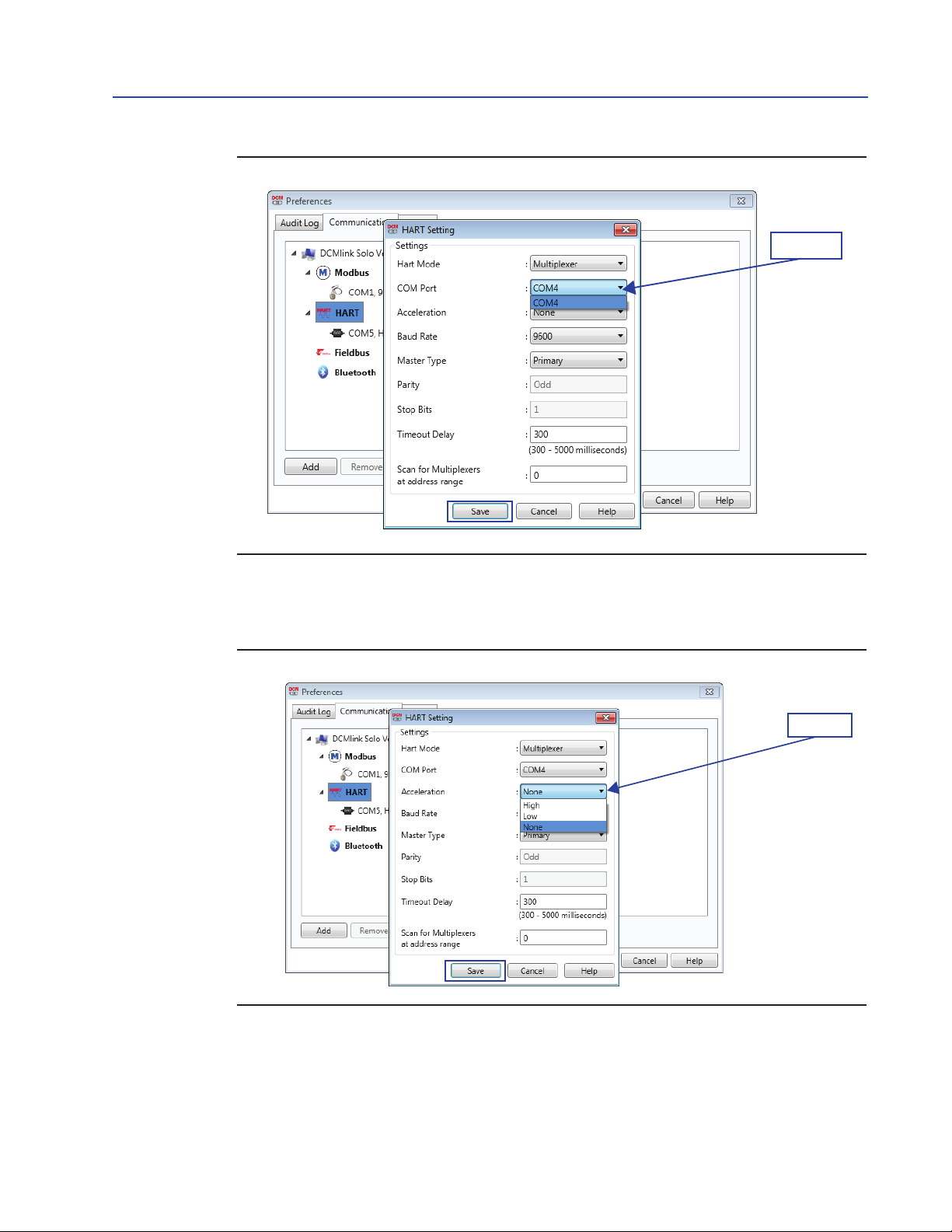
3.5.2.1.6 Click HART Mode and select option Multiplexer.
Figure 57 Conguring HART Port through Modem
3.5.2.1.7 Select COM Port connected to the actuator.
COM Port is generated because of RS485 Modem.
Step 6
38
Setting Up DCMlink Networks
Page 43
Quick Start Guide
DCM-401-0918 Rev. 2.4
Section 3: Setting Up DCMlink Networks
November 2020
Figure 58 COM Port selection
Step 7
3.5.2.1.8 Select Acceleration.
High, Low, None
Figure 59 Acceleration selection
Step 8
Setting Up DCMlink Networks
39
Page 44

Section 3: Setting Up DCMlink Networks
November 2020
3.5.2.1.9 Baud rate:
Figure 60 Baud Rate selection
Quick Start Guide
DCM-401-0918 Rev. 2.4
Available Baud rate is 9600, 19200 or 38400.
Step 9
3.5.2.1.10 Select Master Type:
– Primary: Primary master is communicating device, such as HART
capable control system permanently wired to field instrument.
– Secondary: Secondary master is not permanently wired to field
instrument. A hand-held communicator or a HART modem attached to
computer running DCMlink software typically communicates
as secondary.
Figure 61 Master Type selection
Step 10
40
Setting Up DCMlink Networks
Page 45

Quick Start Guide
DCM-401-0918 Rev. 2.4
Section 3: Setting Up DCMlink Networks
November 2020
3.5.2.1.11 Parity is fixed at Odd.
3.5.2.1.12 Stop Bits is fixed at 1.
3.5.2.1.13 Should be user editable text box the default value should be 300 ms and
the range should be 300 - 5000 ms.
Figure 62
Step 11
Step 12
Step 13
3.5.2.1.14 Scan for Multiplexer at address range. Add address range from 0 to 63.
NOTE:
The Multiplexer address is used by DCMlink internally while detecting the connected
Multiplexer in Network.
Figure 63
Step 14
Setting Up DCMlink Networks
3.5.2.1.15 Click Save.
41
Page 46

Section 3: Setting Up DCMlink Networks
November 2020
Figure 64 COM Port saved
Quick Start Guide
DCM-401-0918 Rev. 2.4
3.5.2.1.16 On Protocol Selection View (navigation pane), right-click on the newly
created COM# Port.
3.5.2.1.17 Click Scan For New Devices.
Figure 65 Scan for New Devices
42
Setting Up DCMlink Networks
Page 47

Quick Start Guide
DCM-401-0918 Rev. 2.4
Section 3: Setting Up DCMlink Networks
November 2020
3.5.2.1.18 View after HART MUX is configured.
Figure 66 View after HART MUX conguration
3.5.2.2 Adding Actuator to Multiplexer
NOTE:
DCMlink Solo must be licensed with a Tag Limit sufficient for the number of connected actuators.
Depending upon the multiplexer, DCMlink Solo can support up to 256 individual loop channels
per multiplexer. User can connect one actuator to each loop channel.
To add a new actuator to a multiplexer:
• Connect HART signal wiring to the multiplexer.
• Apply power to the actuator and multiplexers.
• Right click the multiplexer symbol and select Reset and Rescan the Multiplexer
from the drop-down menu.
• If the actuator is recognized by the software, actuator symbol appears beneath
the multiplexer on the device connection diagram. If no symbol appears, then the
software does not recognize the actuator. Check physical connections and actuator
loop power.
Setting Up DCMlink Networks
43
Page 48

Section 3: Setting Up DCMlink Networks
November 2020
Figure 67 Adding Actuator to Multiplexer
3.5.3 Setup Wireless Network
Quick Start Guide
DCM-401-0918 Rev. 2.4
3.5.3.1 Wireless Gateway
— Set Up Gateway Internet Access for AMS Session
NOTE:
A special CROSSOVER CABLE must be used for this application.
• Connect crossover Ethernet cable between computer and Ethernet #1 port on Gateway.
• On PC navigate to: Control Panel > View Network Connections >Local Area
Connection > Properties > Internet Protocol Version 4 (TCP/IPv4) > Properties.
• Select Use the following IP Address and enter 192.168.1.12 (subnet mask will come
up) select Ok and then Ok on the next prompt.
• Open Internet Explorer and enter the following address: HTTPS://192.168.1.10 and hit
enter. (*If Security certificate message comes up, you may have to select Diagnose
Connection Problem).
• Select Continue to Website and enter for Username admin and Password default.
• Select Explorer in left margin to read devices (this process might take up to
15 minutes).
— Set up a computer using a HART Modem
• Install all software/drivers necessary for HART modem prior to connection.
• Open AMS Device Manager and navigate to Conguration > Add > HART Modem
>Install > Next > Next and select Hand held device as secondary HART master, then
select the correct COM port for HART modem.
• Go to Wireless HART adapter block and check include Wireless HART adapter then
click nish.
44
Setting Up DCMlink Networks
Page 49

Quick Start Guide
DCM-401-0918 Rev. 2.4
Section 3: Setting Up DCMlink Networks
November 2020
3.5.3.2 Wireless THUM
— THUM Programming – Join to Gateway Network Using a PC
Using the Wireless HART THUM Kit (Part No 87263), set up the THUM as shown below:
• Set up computer Internet for Gateway.
• Plug HART modem into computer.
• Open AMS and navigate to Device Connection icon > HART modem > THUM > to
read the parameters.
• Select Configure > Join Device to Network > Enter Network ID and enter the
Network ID inside the cover of the Gateway, click next.
• Enter Join Key (Number shown on THUM Tag). All Three remaining Join Keys are
eight (8) zeros.
• Select Network Configuration on AMS menu and select Add.
— Running AMS to Change the Device Setpoint.
• Navigate and start your AMS Device Manager application.
• Locate and select the Device Connection View in the middle of the toolbar.
• Double click Wireless Network to see devices.
NOTE:
The message Network disruption was detected means no devices are sensed by
gateway. If no devices show up on the screen, right click on Wireless Network and select
Rebuild and Identify hierarchy.
• Expand Gateway > myNet > THUM and double click on the device logo.
• Set Time in the lower left hand corner of the screen to Current from the drop down
box select Yes when prompted to continue.
• Expand Online on the Configure/Setup Screen > Detailed Setup > Valve Control
>Setpoint and select the Change Setpoint method.
• Select Yes and click next when the writing wetpoint requires placing the device in out
of service mode… Prompt shows up.
• Enter the desired setpoint for the device and click Next.
• After receiving the write setpoint success message, select next, then finish to
complete the change setpoint method.
Setting Up DCMlink Networks
45
Page 50

Section 3: Setting Up DCMlink Networks
November 2020
3.5.3.3 Installation of Optional THUM Wireless Adapter
1. Component Installation on M2CP
Table 3. Attach wires from the Wireless HART THUM to the CAM16 J4
CAM 16 THUM
Quick Start Guide
DCM-401-0918 Rev. 2.4
I- White
I+ Yellow
Table 4. Connect Wireless THUM to 320B Board
320B THUM
26 Red
29 Black
2. Component Installation on HQ33
Table 5. Attach wires from the Wireless HART THUM to the CAM16
CAM 16 THUM
I- White
I+ Yellow
Table 6. Connect Wireless THUM to DCM33 Board
HQ THUM
P3-3 Red
P3-4 Black
3. Component Installation on TEC2000/TEC2/EHO
Table 7. Connect Wireless THUM to Actuator
STC THUM
9 Red
10 Black1200 Ohm Series Resistor
24 Green (Optional)
43 Yellow
44 White
46
4. Connect to XTE3000 Actuator
Table 8.
SW5 Pin 1 SW5 Pin 2 SW5 Pin 3 SW5 Pin 4 Connections Mode
OFF OFF ON ON Point to Point
OFF OFF ON ON Split Ranging
ON ON OFF OFF Multidrop
Setting Up DCMlink Networks
Page 51
Quick Start Guide
DCM-401-0918 Rev. 2.4
Section 3: Setting Up DCMlink Networks
November 2020
Figure 68
3.5.4 Setup DeltaV Network
• Connect actuator, DeltaV HART Network.
• Using DeltaV Explorer navigate to actuator.
Figure 69 DeltaV Explorer
• Right click on the actuator and from Context menu user can launch AMS. Once AMS is
launched, actuator can be seen under Navigation view of AMS.
Figure 70 Actuator on AMS
• User can now launch DCMlink.
Setting Up DCMlink Networks
47
Page 52

Section 3: Setting Up DCMlink Networks
November 2020
Quick Start Guide
DCM-401-0918 Rev. 2.4
3.6 Multiplexer Networks for DCMlink SNAP-ON
Once connection is completed with MUX, user needs to configure AMS.
To configure AMS:
Figure 71 Network conguration
— Select Network Component Type and click Add.
— For HART device: HART Multiplexer.
Figure 72 Select Network Component Type
— Click Install and follow screen instructions.
48
Setting Up DCMlink Networks
Page 53

Quick Start Guide
DCM-401-0918 Rev. 2.4
Figure 73 Add HART Multiplexer Wizard-Start
Section 3: Setting Up DCMlink Networks
November 2020
Figure 74 Add HART Multiplexer Wizard-Modem Name
Setting Up DCMlink Networks
49
Page 54
Section 3: Setting Up DCMlink Networks
November 2020
Figure 75 Add HART Multiplexer Wizard-Network Controller
Quick Start Guide
DCM-401-0918 Rev. 2.4
— Select one COM Port from the list.
— When completed you will see a HART Multiplexer added into the Network
Configuration Screen.
Figure 76 Network Conguration
50
Setting Up DCMlink Networks
Page 55

Quick Start Guide
DCM-401-0918 Rev. 2.4
Section 3: Setting Up DCMlink Networks
November 2020
3.6.1 Multiplexer Networks for DCMlink Snap-ON
3.6.1.1 Setting Up Multiplexer Network
DCMlink uses an RS485 Modem to communicate with different actuators through HART
multiplexers Depending upon the multiplexer, DCMlink can support up to 256 individual
loop channels per multiplexer. Refer to Table 9 to determine the number of multiplexers and
actuators that may be connected to a network.
Table 9. Maximum Number of Multiplexers and HART Devices per Network
Multiplexer Type
Maximum Number
of Multiplexers Per
Maximum Number of
Loops Per Multiplexer
Network
MTL4841 Communications Module 31 256
Pepperl+Fuchs 32 255
Each MTL4841 module receives digital data from a maximum of 16 MTL4842 HART
Interface Modules. In turn, each MTL4842 module accesses data from a maximum of 16 HART devices.
The following procedure to set up a multiplexer network:
• Connect physical equipment. Set all multiplexers and the RS485 converter to the same
baud rate.
NOTE:
For details about wiring and connecting equipment, refer to the appropriate instruction guide.
• Apply power to the RS485 converter, multiplexers and actuators.
Setting Up DCMlink Networks
51
Page 56

Section 3: Setting Up DCMlink Networks
November 2020
3.6.1.2 Changing the Multiplexer Tag and Descriptor
Figure 77 Changing the Multiplexer Tag and Descriptor
Quick Start Guide
DCM-401-0918 Rev. 2.4
Enter the name of the
Multiplexer here. Same will
be reected in the DCMlink.
3.6.1.3 Setting Up Pepperl+Fuchs Multiplexer
When adding or removing a submodule from a Pepperl+Fuchs multiplexer, user must
reconfigure the multiplexer to indicate the changes. To setup Pepperl+Fuchs multiplexer:
• On each Pepperl+Fuchs slave module, Set Slave Address switch to an unused value so
that each module has its own individual setting.
• On Pepperl+Fuchs Module Setup screen, check those modules that are installed.
Figure 78 Pepperl+Fuchs Module Setup Screen
52
Setting Up DCMlink Networks
Page 57
Quick Start Guide
DCM-401-0918 Rev. 2.4
3.6.1.4 Setting Up MTL Multiplexer
Figure 79 MTL Multiplexer
Section 3: Setting Up DCMlink Networks
November 2020
3.6.1.5 Viewing Multiplexers Status
User can view the status and add a tag and descriptor to each multiplexer on the network. For a
Pepperl+Fuchs multiplexer, user can also define which modules are included in the multiplexer.
Figure 80 Multiplexer Information Window
Multiplexer fields:
• Mux #: The multiplexer address, determined by the address switch settings on the
multiplexer or communications module.
• Unique ID: The last six digits of a unique ID number assigned to the multiplexer by
the manufacturer.
• Tag: A name assigned to the multiplexer from the tag and descriptor screen.
• Description: A description assigned to the multiplexer from the Tag and
• Manufacturer: The multiplexer manufacturer, Emerson, MTL, ELCON, or P&F.
Setting Up DCMlink Networks
Descriptor screen.
53
Page 58

Section 3: Setting Up DCMlink Networks
November 2020
• Device Type: HART Interchange for a 2530H1 HART Interchange Multiplexer, MTL4841
Communications Module for a MTL4840 HART Maintenance System, KFD HART
Multiplexer System for a Pepperl+Fuchs multiplexer, or an ELCON Mux.
• Univ. Command Rev.: The HART command language revision number, always 5.
• Instr. Command Rev.: The multiplexer or communications module firmware
revision number.
• Scanning: Alert scanning. Should always be disabled when not viewing the Network
Scan window.
• Scan Cmd: HART command level returned to the multiplexer or communications
module by the instrument if an alert occurs. May be a1 or a3.
• Date: The date data was entered.
• Message: A message programmed into the multiplexer or communications
module software.
• Gender: Whether the multiplexer or communications module is a primary master or
secondary master.
• Loop Search: Currently the multiplexer or communications module only searches for
single analog loops, those loops where the instrument polling address is 0.
• Gateway Device: HART signaling scheme. Always RS485 - Bell 202.
• Software Rev.: Revision number of the software installed in the multiplexer or
communications module.
• Hardware Rev.: Hardware revision level.
• Retry Count: Number of times multiplexer or communications module attempts to
send a command to the instrument. Should be 2 after initialization.
Quick Start Guide
DCM-401-0918 Rev. 2.4
3.7 AMS SNAP-ON Setup
AMS SNAP-ON is a software application that is installed as an integral part of AMS Device
Manager to extend its functionality. AMS SNAP-ON adds the diagnostic test capabilities of
DCMlink software to AMS Device Manager.
A USB hardware key is not used for installing AMS DCMlink SNAP-ON. However, AMS Device
Manager must be licensed for the AMS DCMlink SNAP-ON. To install AMS DCMlink SNAP-ON,
user must first have installed a properly licensed copy of AMS Device Manager.
3.7.1 User Setup
— Installing DCMlink SNAP-ON.
— Starting AMS DCMlink SNAP-ON.
54
Setting Up DCMlink Networks
Page 59

Quick Start Guide
DCM-401-0918 Rev. 2.4
Section 3: Setting Up DCMlink Networks
November 2020
CAUTION
!
Do not run DCMlink SOLO at the same time when using AMS Device Manager or AMS
DCMlink SNAP-ON. Running both simultaneously may cause communication errors.
NOTE:
To successfully use DCMlink SNAP-ON, user must be familiar with using AMS Device Manager.
Refer to the AMS online User’s Guide.
• To make DCMlink SNAP-ON work on AMS 12.5 or below, please ensure to add
Computer-Name (DCMlinkUser) as the domain and password (DCMlink@123) to the
AMS User Manager dialog. After adding the user to the AMS, make sure to add groups
and select all groups for the DCMlinkUser, followed by granting of permissions.
See below for a screen capture.
• For AMS 13.0 and above, add user login to AMS User Manager dialog. This will launch
AMS 13.0 and above using the user login credentials directly from the system.
Figure 81 AMS Device Manager -User Manager
• Start AMS Device Manager by selecting Start> Programs > AMS > AMS system from
the Windows taskbar.
• The AMS Explorer or Device Connection View window displays.
• AMS displays the communication devices (modem, multiplexer) that are connected to
the PC running AMS and the AMS DCMlink SNAP-ON. Right-click device icon and select
Scan All Devices to locate connected HART instruments.
Setting Up DCMlink Networks
55
Page 60

Section 3: Setting Up DCMlink Networks
November 2020
Figure 82 AMS Device Manager Device Connection View
• When actuator icon appears, right-click the actuator icon and select SNAP-ON/Linked
Apps > DCMlink from the context menu.
Figure 83 Right-Click Communications Device Icon to Open Menu
Quick Start Guide
DCM-401-0918 Rev. 2.4
56
Setting Up DCMlink Networks
Page 61

Quick Start Guide
DCM-401-0918 Rev. 2.4
Section 3: Setting Up DCMlink Networks
3.8 Troubleshooting Communication Issues
Table 10. Installation Issues Question and Answer Table
Section Question and Answer
Serial Ports Question:
DCMlink software does not detect all of my serial ports.
How do I enable DCMlink Software to use a port that it doesn’t
automatically detect?
Answer:
In the PreferenceSetting.XML le, ModbusSettings section, user can add a entry
for ModbusSetting.
If the user makes this change while DCMlink Software is running, the user will
have to exit and restart the software for this change to take effect.
COM Port Question:
DCMlink Software isn’t detecting the COM port. What could be causing
this problem?
Answer:
Close DCMlink and relaunch application. If the problem persists, restart the
computer. Alternatively, the user can try programs, such as Allen Bradley or
competitive valve suppliers, etc., that may be using the COM port.
Other causes may include:
The power saving option is set and has caused the port to use the low power
option. You need to set the power saving to none and delete and reinstall the
COM port. The COM ports hardware is malfunctioning. To solve this, please
contact your System Administartor
Communication
Errors
in DCMlink
Question:
I am getting communication errors when performing operations with
DCMlink. What can I do to x the errors?
Answer:
In the PreferenceSetting.XML le, ModbusSetting section, try changing the
value of delay [Timeout delay]. If you make this change while DCMlink Software
is running, the user will have to exit and restart the software for this change to
take effect.
November 2020
Setting Up DCMlink Networks
57
Page 62

World Area Conguration Centers (WACC) offer sales support, service,
inventory and commissioning to our global customers.
Choose the WACC or sales ofce nearest you:
NORTH & SOUTH AMERICA
19200 Northwest Freeway
Houston TX 77065
USA
T +1 281 477 4100
Av. Hollingsworth
325 Iporanga Sorocaba
SP 18087-105
Brazil
T +55 15 3413 8888
ASIA PACIFIC
No. 9 Gul Road
#01-02 Singapore 629361
T +65 6777 8211
No. 1 Lai Yuan Road
Wuqing Development Area
Tianjin 301700
P. R. China
T +86 22 8212 3300
For complete list of sales and manufacturing sites, please visit
www.emerson.com/actuationtechnologieslocations or contact us at
info.actuationtechnologies@emerson.com
MIDDLE EAST & AFRICA
P. O. Box 17033
Jebel Ali Free Zone
Dubai
T +971 4 811 8100
P. O. Box 10305
Jubail 31961
Saudi Arabia
T +966 3 340 8650
24 Angus Crescent
Longmeadow Business Estate East
P.O. Box 6908 Greenstone
1616 Modderfontein Extension 5
South Africa
T +27 11 451 3700
EUROPE
Holland Fasor 6
Székesfehérvár 8000
Hungary
T +36 22 53 09 50
Strada Biffi 165
29017 Fiorenzuola d’Arda (PC)
Italy
T +39 0523 944 411
www.emerson.com
VCIOM-14646-EN ©2020 Emerson. All rights reserved.
The Emerson logo is a trademark and service mark of Emerson Electric Co.
All other marks are property of their respective owners.
The contents of this publication are presented for information purposes only,
and while every effort has been made to ensure their accuracy, they are not
to be construed as warranties or guarantees, express or implied, regarding
the products or services described herein or their use or applicability. All sales
are governed by our terms and conditions, which are available on request.
We reserve the right to modify or improve the designs or specifications of our
products at any time without notice.
 Loading...