


M2CP Digital Futronic User Manual
84829 Rev F
I
NTRODUCTION
The Digital Futronic module uses the latest integrated microcontroller technology to enable one
electronics module to perform valve actuator modulating and positioning control from analog control
signals. The control module uses EIM’s M2CP TBM01 termination panel for interface of all analog control
types. The Digital Futronic module converts 4-20mA analog input to digital for processing and from digital
to 4-20mA analog output for position feedback. The Digital Futronic module controls four EIM motor
control starter types.
1) Futronic II Electro-mechanical AC motor starter
2) Futronic III SCR H-Bridge Solid-state DC motor starter (Powered by 115VAC, 1-Ph)
3) Futronic IV Triac Solid-state (SSR) AC motor starter
4) Futronic VII MOSFET Solid-state pure DC motor starter (Powered by 24VDC or 48VDC)
F
EATURES AND SPECIFICATIONS
Digital microcontroller adapts to any actuator and valve size, speed/stoke-time, process pressure, etc. by
automatically tuning controls to obtain maximum accuracy without any user adjustments for dead band,
delay time, etc.
Automatic calibration of position input to valve travel limits.
Built-in protection for motor and motor controls.
DC motor speed control for Futronic III and Futronic VII.
Easy setup and calibration to user’s external analog control signal input and analog feedback output. All
setup and calibration adjustments by on-board DIP switches and two miniature push buttons.
LED indicators for normal/fault operating conditions, setup mode, loss of analog signal, and solid-state
motor control output.
Isolated Analog Input: 4-20mA with 12-bit (.025%) resolution (calibration range of 0-24mA). 210 Ohms
input resistance. Operates from 10V to 32V loop supply. Allows up to 750 Ohms loop resistance at 24V.
Isolated Analog Output: 4-20mA with 16-bit (.0015%) resolution (calibration range of 0-24mA). Drive loop
resistance up to 750 Ohms. True current source with internal 24VDC power supply. No external power
source required to power loop. Internal automatic resetting fuse for 24VDC power supply.
Isolation dielectric strength: 2500V AC for 1 Minute (Input to output and I/O to ground).
Inverted Analog I/O Option: where 20mA = close valve position and 4mA = open valve position.
Go To Default Position Option: On loss of control signal, user selected default valve position anywhere
between 0 and 100%.
Control Accuracy: Futronic II mode +/- 1.0% @ 15 second stroke time or greater
Futronic III mode +/- 0.25% @ 15 second stroke time or greater
Futronic IV mode +/- 0.5% @ 15 second stroke time or greater
Futronic VII mode +/- 0.25% @ 15 second stroke time or greater
Nonlinearity: <0.05% of calibrated analog input and output over full range of 0-100%.
Operating Temperature Range: -40C to +85C (-40F to +185F), Humidity: 10% - 95% (Non-condensate)
EIM Company, Inc 13840 Pike Road Missouri City, TX 77489 (281) 499-1561 Page 1
M2CP Digital Futronic User Manual
84829 Rev F
I
NSTALLATION AND WIRING
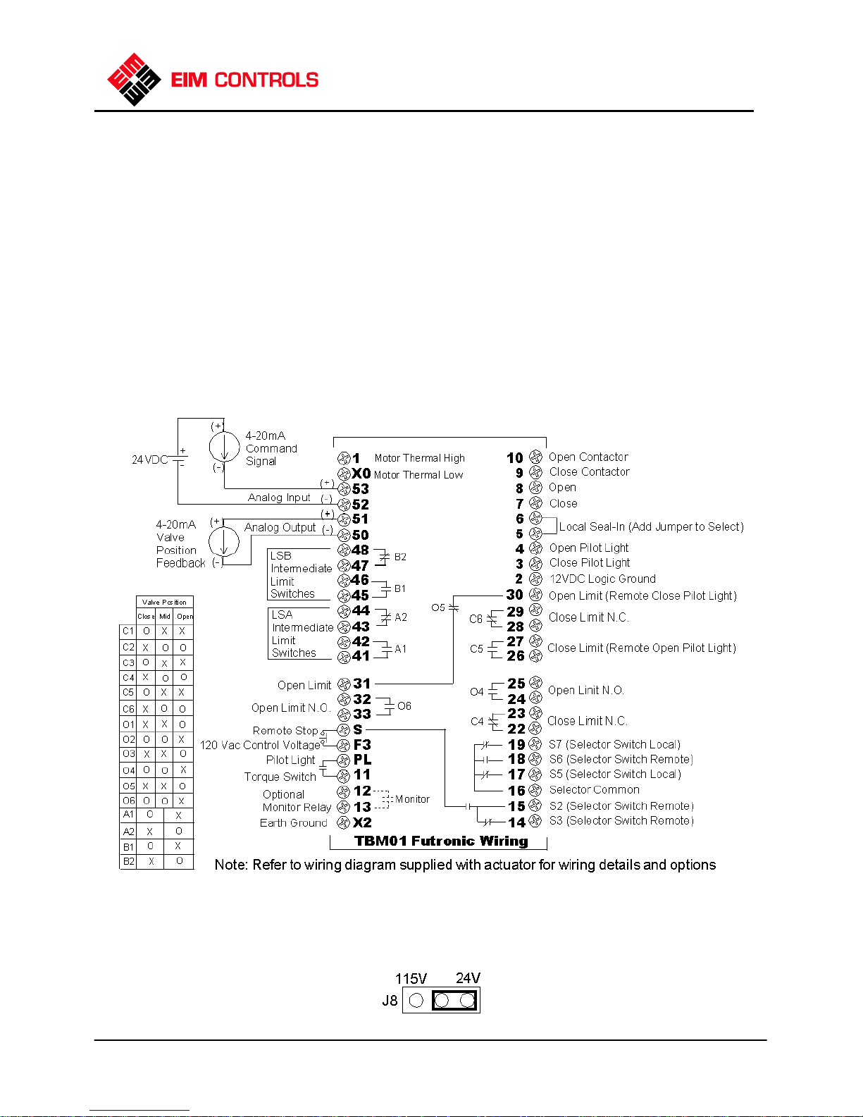
Refer to the wiring diagram supplied with the actuator for wiring details and options supplied with the
system. Figure 1 below is generic and provided primarily for wiring 4-20mA analog input and output
signals. Refer to Figure 1 for proper wiring of analog I/O and associated polarities relative to external
equipment and power supplies. Use the following rules when wiring analog I/O signals.
1) Route analog I/O cables into actuator enclosure through separate conduit entries from power wiring.
2) Always use twisted-pair instrumentation cable for wiring 4-20mA analog input and output signals.
3) Use shielded cable when analog signals are being installed in or routed through high noise areas.
4) If shielded cable is used, earth ground the shield by connecting only one end of the shield to earth.
5) Instruments or control equipment must source current to the analog input of the Digital Futronic.
6) Remote current source to analog input must have own power source, or an external supply is required.
7) Do not connect an external power source to the 4-20mA analog output of the Digital Futronic module.
8) The Digital Futronic module contains its own internal 24VDC power supply for the 4-20mA output and
sources current to external instruments or control equipment.
I
MPORTANT NOTICE
before the Digital Futronic card will operate.
:
Jumper J8 located on the bottom of TBM01 must be in the 24V position
EIM Company, Inc 13840 Pike Road Missouri City, TX 77489 (281) 499-1561 Page 2
F
IGURE
1

M2CP Digital Futronic User Manual
I
84829 Rev F
M
ODULE SETUP AND CALIBRATION
DIP Switch SW3 has 6 switches designated as S1-S6 for calibration and mode selection as summarized
below. There are two miniature push buttons labeled UP and DOWN. Refer to Figure 2 for location of DIP
switches and push buttons. Switches S1-S3 are used for setup and calibration and switches S4-S6 are
used for mode selection. If any one or more of switches S1, S2 or S3 are on, the actuator is in setup
mode. The actuator returns to normal operating mode when all three switches S1-S3 are turned off.
When changing from setup mode to normal operating mode, do not turn off power to the actuator for at
least 5 seconds to allow the controller to store the new setup values to EEPROM nonvolatile memory.
Setup and normal operating modes are designated by LED 1 as defined below.
NDICATOR LIGHTS
LED 1
► Slow Flash =
Normal Operating Mode.
► Rapid Flash =
Setup mode (any one of
switches S1 through S3
are on).
► Alternating Between
Slow and Rapid Flash =
Lost Analog Input
(Command) Signal.
► Steady On or Steady
Off = Module failure.
LED2
► On when Solid State
Relay (SSR or SCR) is On
(control power applied to
output).
F
IGURE
2
F
IRMWARE VERSION NUMBER DISPLAY
Each time the actuator is powered up, the firmware version number is displayed by LED1 with the
following sequence of flashes.
At power up LED1 stays on for 4 seconds and then begins to flash. Count the number of times the LED
flashes on before it turns on solid again for 2 seconds. The number of flashes is the high order firmware
version number.
After a 2-second solid on delay, the LED will begin to flash again. Count the number of flashes until the
LED turns on solid again for 4 seconds. The number of flashes is the low order firmware version number.
After the 4-second delay, LED1 will then flash at the normal rate defined under Indicator Lights above.
If unable to correctly count the number of flashes to properly determine the firmware version number,
then cycle power to the actuator and the display process will repeat.
EIM Company, Inc 13840 Pike Road Missouri City, TX 77489 (281) 499-1561 Page 3

M2CP Digital Futronic User Manual
84829 Rev F
S
ETUP
Normal Run Mode Turn off S1, S2 & S3 for Normal Run Mode
(S1,S2,S3 OFF)
Cal Analog Input Press UP to set Span (20mA) input
(S1 ON) Press DOWN button to set Zero (4mA) input
Cal Analog Output Press UP to increase 4mA output
Zero (S2 ON) Press DOWN to decrease 4mA output
Cal Analog Output Press UP to increase 20mA output
Span (S3 ON) Press DOWN to decrease 20mA output
Set Modulation Press UP to select 3-Ph motor (delay = 2 sec)
Delay (S1, S2 ON) Press DOWN to select 1-Ph motor (delay = 12 sec)
Set Default Position Press UP or DOWN to accept current valve
(S2 & S3 ON) position as default position
Invert Analog I/O Press UP to Select Inverted Mode
(S1, S2 & S3 ON) Press DOWN to Disable Inverted Mode
Double Deadband Press UP to Double control deadband defined (see note)
(S1 & S3 ON) Press DOWN to Return deadband to default values
N
OTE:
Doubling the control deadband (bandwidth) reduces control accuracy by twice the values stated
on Page 1. Use this function only for difficult to control applications. Doubling the deadband affects
accuracy of all four versions of actuator operating controls, as follows:
Default Double
Futronic II mode +/- 1.0% +/- 2.0%
Futronic III mode +/- 0.25% +/- 0.5%
Futronic IV mode +/- 0.5% +/- 1.0%
Futronic VII mode +/- 0.25% +/- 0.5%
M
ODE SELECTION
S4 ON = Go to Default Position on loss of analog input control signal
S4 OFF = Stay Put on loss of analog input control signal
S5 OFF and S6 OFF Select Futronic II mode (Electromechanical motor starter)
S5 ON and S6 OFF Select Futronic III mode (SCR solid-state DC motor starter)
S5 OFF and S6 ON Select Futronic IV mode (Triac solid-state (SSR) motor starter)
S5 ON and S6 ON Select Futronic VII mode (MOSFET solid-state (SSR) motor starter)
EIM Company, Inc 13840 Pike Road Missouri City, TX 77489 (281) 499-1561 Page 4

M2CP Digital Futronic User Manual
84829 Rev F
C
ALIBRATION PROCEDURES
C
AUTION
Calibrate Analog Input (Position Command Signal)
1) Connect 4-20mA calibration source to TBM Terminals 52 (-) and 53 (+).
2) Set S1 to ON (up) position. Apply 4mA zero calibration signal and then press DOWN push button.
3) Apply 20mA full-scale (span) calibration signal and then press UP push button.
4) Return S1 to OFF (down) position.
N
OTE
connect to TBM terminals 50(-) and 51(+) to monitor the analog input at the output.
Calibrate Analog Output (Position Feedback)
1) Connect calibrated 4-20mA meter to TBM Terminals 50 (-) and 51 (+).
2) Set S2 to ON (up) position.
3) Press UP or DOWN push button to increase or decrease zero (4mA) analog output signal.
4) Return S2 to OFF (down) position.
5) Set S3 to ON (up) position.
6) Press UP or DOWN push button to increase or decrease full-scale (20mA) analog signal.
7) Return S3 to OFF (down) position.
Select Modulation Delay Time
1) Set S1 and S2 to ON (up) position.
2) Press UP push button to select 3-Phase motor (Modulation delay = 2 seconds)
3) Press DOWN push button to select 1-Phase motor (Modulation delay = 12 seconds)
4) Return S1 and S2 to OFF (down) position.
Enable/Disable Go-To-Position on Loss of Signal
1) Set S4 ON (up) to Enable Go-To-Position on loss of signal.
2) Set S4 OFF (down) to Disable Go-To-Position on loss of signal, i.e. Stay in last position on loss of
signal.
Set Default Position (Position of valve on loss of analog input signal when S4 enabled)
N
OTE
selector switch in the “REMOTE” position, else leave the selector in the “OFF” position to prevent the
valve from moving.
1) Connect 4-20mA calibration source to TBM Terminals 52 (-) and 53 (+).
2) Set S2 and S3 to ON (up) position.
3) Apply calibration signal for the desired position (4-20mA or 0-100%).
4) Press either UP or DOWN push button to accept the analog input as the default position.
5) Return S2 and S3 to OFF (down) position.
Calibrate to Limits:
from limit to limit for two full strokes. This allows the controller to calibrate the analog position feedback to
the position limits before operation in remote control mode.
:
Place selector switch in “OFF” position before calibrating actuator
: When S1 is ON, the analog input signal is fed to the analog output. A current meter may be
:
If it is desirable for the valve to move to position while setting the default position then place the
When setup is complete, place selector switch in “Local” mode and stroke valve
EIM Company, Inc 13840 Pike Road Missouri City, TX 77489 (281) 499-1561 Page 5

M2CP Digital Futronic User Manual
84829 Rev F
D
EFINITIONS
Command = 4-20mA analog input position command signal generated by remote control equipment.
Same as position command setpoint. Zero and Full-scale calibrated by user.
Position = 0-5V valve position analog input signal generated by Hall-effect Position Sensor (HPS). Zero
and Full-scale automatically calibrated by controller based on LSC and LSO valve travel limit switches.
Feedback = 4-20mA analog output signal for feedback of valve position to remote control equipment.
Zero and Full-scale calibrated by user.
Invert = Inverted calibration of 4-20mA command where close position = 20mA, and open position =
4mA. Feedback is also inverted.
Deadband = Allowable error tolerance to keep valve stopped, i.e. do not turn on motor control outputs.
Deadband can be configured by the user as the defined default values or double the default values.
Deadband has a beginning default value based on selected operating mode (motor starter type) and then
controller automatically adjusts the deadband to obtain the best accuracy.
Default deadband based on motor starter type:
Futronic II = +/-1.0% deadband
Futronic III = +/-0.25% deadband
Futronic IV = +/-0.50% deadband
Error = Difference between Command and Position.
Error=Command-Position
If not Invert and Error=Positive then open valve
If not Invert and Error=Negative then close valve
If Invert and Error = Positive then close valve
If Invert and Error= Negative then open valve
Nonlinearity = Difference between analog input and analog output at current valve position over the full
valve operating range.
Close Coast = Difference between Position when the motor is turned off and Position when the valve
stops moving in the close direction. Coast is caused by both inertia of the motor and latency of Position
update due to analog input filtering. The controller measures close coast to automatically tune control for
maximum accuracy.
Open Coast = Difference between Position when the motor is turned off and Position when the valve
stops moving in the open direction. The controller measures open coast to automatically tune control for
maximum accuracy.
Modulation Delay = Time between when the motor is turned off until the motor can be started again. This
delay prevents excessive number of starts of the motor, preventing overheating the motor and premature
burnout of the reversing contactor. Modulation delay also prevents valve plugging when the actuator
reverses direction. If a three phase motor is used, the delay time is 2 seconds or 1800 starts per hour. If a
single phase, capacitor start, AC motor is used, then the delay is 12 seconds or 300 starts per hour. The
delay between motor control pulses while the valve is being jogged to position is automatically reduced to
one second.
EIM Company, Inc 13840 Pike Road Missouri City, TX 77489 (281) 499-1561 Page 6

M2CP Digital Futronic User Manual
84829 Rev F
Turn-off Delay = 10 Seconds = Delay after motor stops before turning off Open or Close reversing
contactor outputs unless a reversal in direction is required. If reversal in direction, then Modulation Delay
time is used. Valid only when Futronic III or Futronic IV modes are selected. This delay prevents
excessive operation of the contactor while modulating or the 4-20mA command signal is being ramped by
a PID control loop.
Accel = Time required to accelerate motor speed from zero to full speed when motor is started due to
Error greater than Deadband. The purpose of Accel is to soft-start the motor and to help prevent control
overshoot when making small position changes. Accel is inversely proportional to Error and is
automatically adjusted by the controller.
Decel = Time required to decelerate motor speed from full speed to zero while Position is approaching
Command position setpoint. Valid only when Futronic III or Futronic IV modes are selected. Decel is
proportional to Error. If motor is at full speed (Accel time expired) and Error is less than tuned parameter
then the controller begins decelerating motor speed over a period of time where Decel=(ErrorDeadband)*T Sec. Decel is activated only when Accel time has expired. This prevents motor stall when
making small position changes. If Error is less than Deadband then Decel=0.
DC Motor Speed Control = Full speed of the motor is set at the factory using a potentiometer on the
SCR motor control module. The Digital Futronic module regulates full speed of the motor, maintaining
accurate speed/valve travel time regardless of high or low power line conditions and varying load
conditions. Valid only for Futronic III.
EIM Company, Inc 13840 Pike Road Missouri City, TX 77489 (281) 499-1561 Page 7
 Loading...