

Eilersen MCE2035, MCE2010, MCE9601 User Manual

Kokkedal Industripark 4
DK-2980 Kokkedal
Denmark
info@eilersen.com
Tel +45 49 180 100
Fax +45 49 180 200
MCE2035 PROFIBUS DP MODULE
Transfer the status and weight of digital loadcells
Applies for:
Program no.: CONCTR_4.091117.0
Document no.: 1117mu2035-2010-0a.DOC
Date: 2011-05-17
Rev.: 0a

MCE2035: User manual
1) CONTENTS
1) CONTENTS.....................................................................................................................................2
2) INTRODUCTION ...........................................................................................................................3
2.1 Introduction.................................................................................................................................3
2.2 Profibus-DP specification...........................................................................................................3
3) MCE2010 DESCRIPTION..............................................................................................................4
4) MCE9601 DESCRIPTION..............................................................................................................6
5) DATA EXCHANGE .......................................................................................................................8
5.1 Profibus-DP communication using PPO.....................................................................................8
5.2 Data formats................................................................................................................................9
5.2.1 Unsigned integer format (16 bit)......................................................................................9
5.2.2 Signed integer format (32 bit)..........................................................................................9
5.2.3 IEEE754 floating point format (32 bit)..........................................................................10
5.3 Measurement time.....................................................................................................................11
5.4 Filtering.....................................................................................................................................11
5.5 Scaling.......................................................................................................................................11
6) DATA PROCESSING...................................................................................................................12
6.1 Zeroing, calibration and weight calculation..............................................................................12
6.1.1 Zeroing of weighing system...........................................................................................12
6.1.2 Corner calibration of weighing system ..........................................................................12
6.1.3 Calculation of uncalibrated system weight ....................................................................13
6.1.4 System calibration of weighing system..........................................................................13
7) INSTALATION OF SYSTEM......................................................................................................14
7.1 Checklist during installation.....................................................................................................14
8) HARDWARE DESCRIPTION .....................................................................................................15
8.1 MCE2035 overview..................................................................................................................15
8.2 Connection of power and load cells..........................................................................................16
8.3 DIP-switch settings...................................................................................................................17
8.4 Light Emitting Diodes...............................................................................................................17
8.5 Jumpers.....................................................................................................................................18
8.6 Profibus-DP connector..............................................................................................................19
8.7 Hardware Selftest......................................................................................................................19
8.8 Update times .............................................................................................................................19
9) STATUS CODES ..........................................................................................................................20
Version: 2011-05-17, rev.: 0a Page: 2

2.1 Introduction
This document describes the use of a MCE2035 Profibus-DP module from Eilersen Electric, when it is equipped with the program listed on the front page.
With the program specified on the front page, the MCE2035 Profibus-DP module is capable of transmitting weight and status for up to 4 load cells in a single telegram. Each load
cell is connected to the Profibus-DP module through a load cell interface module.
It is possible to connect the MCE2035 Profibus-DP module to a Profibus-DP network,
where it will act as a slave. It will then be possible from the Profibus-DP master to read
status and weight for each of the connected load cells. Functions as zeroing, calibration and
calculation of system weight(s) must be implemented on the Profibus-DP master.
By use of DIP-switches it is possible to:
- select measurement time.
- select scaling.
- include one of 3 different FIR filters.
Exchange of data between master and slave takes place as described in the following.
MCE2035: User manual
2) INTRODUCTION
2.2 Profibus-DP specification
The MCE2035 Profibus-DP module confirms to the following Profibus-DP specifications:
Protocol: Profibus-DP
Communications form: RS485
Module type: Slave
Baud rates [kbit/sec]: 9.6, 19.2, 93.75, 187.5, 500, 1500, 3000, 6000, 12000
Profibus address: 0-127
Profibus connection: 9-pin sub-D (female) connector
IMPORTANT: Load cell modules and instrumentation must be placed outside the
hazardous zone if the load cells are used in hazardous ATEX (Ex) area. Furthermore,
only ATEX certified load cells and instrumentation can be used in ATEX applications.
Version: 2011-05-17, rev.: 0a Page: 3
MCE2035: User manual
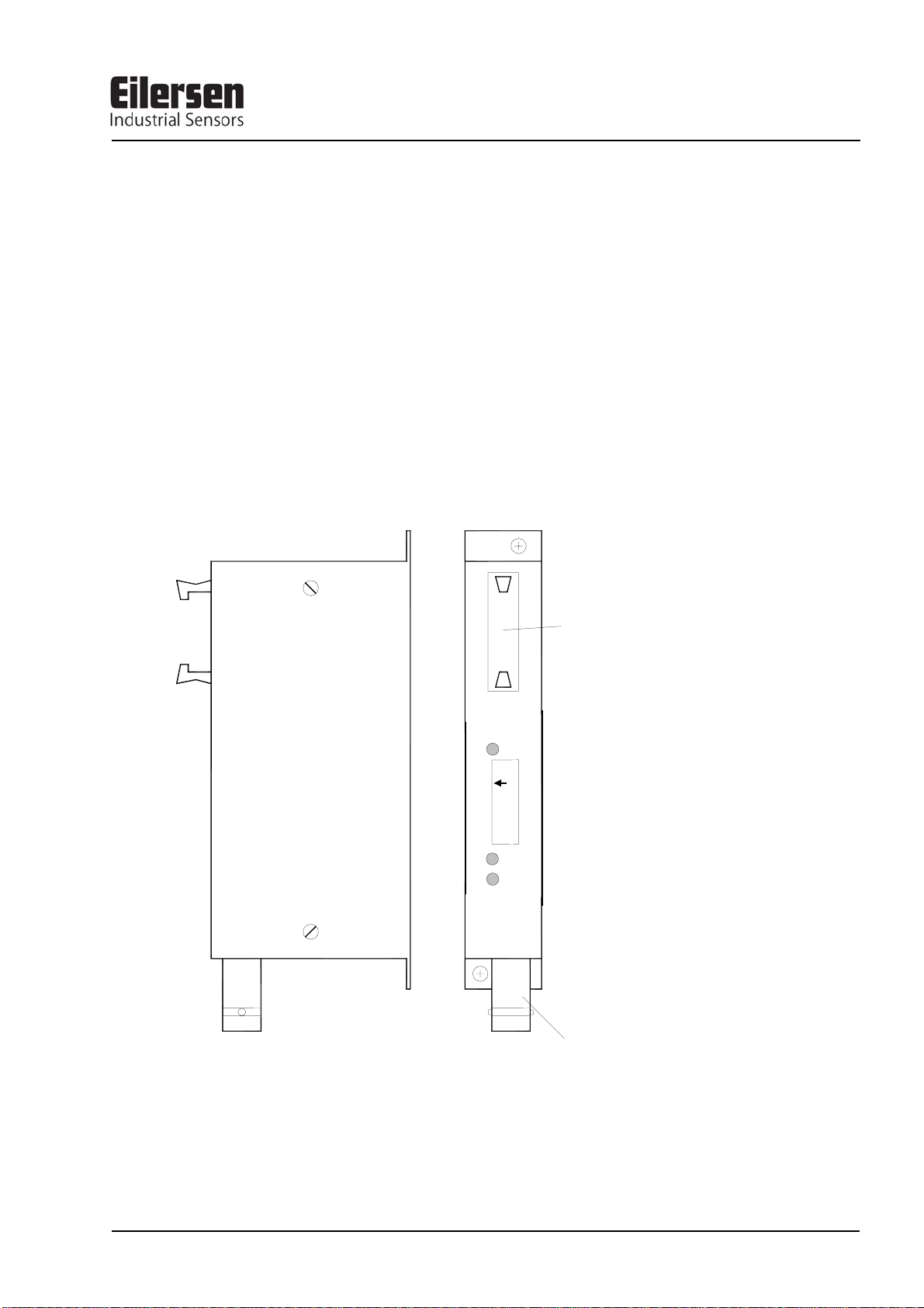
3) MCE2010 DESCRIPTION
Below the layout of the MCE2010 load cell module is shown. Before using the system the
load cells must be connected to the load cell modules.
Please notice that the load cell and the load cell module MUST be marked
with the same year/serial number. These are printed on the type-plate of the
load cell and on a small sticker placed below the BNC plug on the load cell
module. Load cells and load cell modules MUST NOT be intermixed because
the program in each load cell module is SPECIALLY adapted to one load
cell only (and only this load cell). The load cell module MUST be connected
to exactly the load cell it is intended for and vice versa.
TXBB
1
ON
8
D1
SYNC
ERR
MCE2010
Eil ersen Elec t r ic
SW
1
Flat cable connector
10 contacts
BNC connector
for loadcell
The load cell modules are connected to each other using the supplied cable (10 pole ribbon
cable). The MCE9601 terminal module (the one with connection terminals) and the
MCE2035 Profibus-DP module are connected using the same cable.
Version: 2011-05-17, rev.: 0a Page: 4
MCE2035: User manual
All switches (SW1) in the load cell module must be at the correct position before use.
Please notice that the switches (SW1) are only read once during power-up. If a change in
the switch setting is necessary the power has to be disconnected and then reconnected (after 10 seconds). Then the MCE2010 load cell module recognizes the new switch setting.
The switches SW1.1 to SW1.4 are used to select different modes of operation. The below
table is valid for the normal standard software in the load cell module. Unless expressly
specified, the default settings must normally be used.
MCE2010 SW1.1 to SW1.4
SW1 No Default setting Function
1
2
3
4
OFF Baud rate
OFF: 115200
ON: 230400
ON Filter, MSB
ON Filter, LSB
OFF Not used
Switch SW1.5 to SW1.8 are used for address selection. All load cell modules must have
unique addresses ascending from 0 with no gaps unless expressly specified otherwise. No
addresses may be skipped and no addresses may be used by more than one load cell module. In systems with 1-8 load cells switch SW1.5 must be set to OFF.
MCE2010 SW1.6 to SW1.8
SW1.5 SW1.6 SW 1.7 SW1.8 Address
OFF OFF OFF OFF 0
OFF OFF OFF ON 1
OFF OFF ON OFF 2
OFF OFF ON ON 3
OFF ON OFF OFF 4
OFF ON OFF ON 5
OFF ON ON OFF 6
OFF ON ON ON 7
The three LED’s are used to indicate the following conditions:
MCE2010 LED’S
TXBB
D1
SYNC ERR
Green Lit whenever the load cell module transmits data. Must be
on/flashing rapidly whenever the system is started.
Yellow No synchronisation between load cell modules: One or more load
cells not connected to load cell module or poor connection.
Red No load cell synchronisation: No load cell connected to load cell
module or poor connection.
Version: 2011-05-17, rev.: 0a Page: 5

MCE2035: User manual
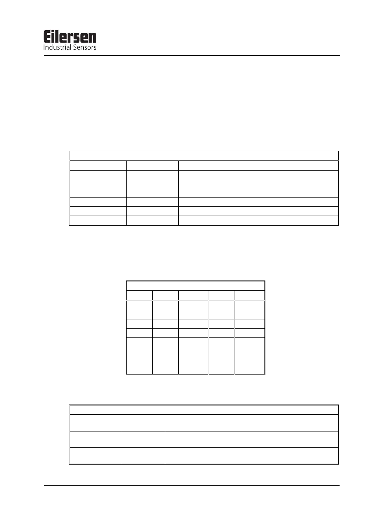
4) MCE9601 DESCRIPTION
Below the layout of the MCE9601 terminal module is shown. The MCE9601 module is
used for connection between the Eilersen Electric digital load cell bus at one side and
power supply/equipment at the other side.
2
J
D3
D2
D1
JU1
Gnd
B
A
1
J
Gnd
+24Vdc
Gnd
I/O
The J1 terminal block is used for connection of the following:
• Terminals Gnd and B (-) and A (+) gives access to the RS485 bus of all equipment
connected to the load cell bus.
• Terminals Gnd and +24Vdc provides external power to the equipment connected to the
load cell bus. These terminals have to be connected to an external +24VDC power supply.
• Terminals Gnd and I/O are the internal synchronization signal used by the load cell
modules. Normally these terminals have no external connection and must be left open.
The J2 connector is used for connecting equipment (load cell modules, communication
modules etc.) on the digital load cell bus by using the supplied ribbon cable with mounted
connectors.
The JU1 jumper is used for hardware synchronisation. Normally this jumper should be left
in the default factory setting which is ON.
The light emitting diodes on the MCE9601 module have the following function:
LED Function
D1
(Green)
D2
(Yellow)
D3
(Red)
RS485 Communication. This LED should be ON during normal operation (Actually it is
flashing quickly, but this can look like a steady light).
This LED should be OFF during normal operation. If this lamp is lit, the I/O pin is at reversed polarity.
Hardware Synchronisation. This LED should be ON during normal operation (Actually
it is flashing quickly, but this can look like a steady light).
Version: 2011-05-17, rev.: 0a Page: 6
 Loading...