


Kokkedal Industripark 4
DK-2980 Kokkedal
Denmark
info@eilersen.com
Tel +45 49 180 100
Fax +45 49 180 200
Applies to:
Software: STDLIM.140630.2v0
Document no.: 0630mu5024-2v0.doc
Date: 2017-04-05
Rev.: 2v0
5024 WEIGHING TERMINAL
Basic system with automatic dosing

5024 STDLIM.140630.2v0: Users guide
WWW.EILERSEN.COM
Version: 2017-04-05, rev.: 2v0 Page: 2
1) Contents
1) Contents .................................................................................................................. 2
2) Operation ................................................................................................................. 5
2.1 Introduction ......................................................................................................... 5
2.2 Power-up sequence ............................................................................................... 5
2.2.1 Zeroing during power up .................................................................................. 5
2.3 Operator panel ...................................................................................................... 5
2.4 Keyboard lock ....................................................................................................... 6
2.5 Menus .................................................................................................................. 6
2.6 Screens overview .................................................................................................. 7
2.7 Data entry ............................................................................................................ 7
2.7.1 Locking and unlocking parameters ..................................................................... 7
2.7.2 Entry using selection list ................................................................................... 8
2.7.3 Entry of numbers ............................................................................................. 9
3) Screens .................................................................................................................. 12
3.1 Normal display .................................................................................................... 12
3.2 Dosing ............................................................................................................... 13
3.2.1 Setting Coarse and Fine limits ......................................................................... 14
3.2.2 Start/Stop of dosing ....................................................................................... 14
3.3 Totals ................................................................................................................ 15
3.3.1 Totals menu .................................................................................................. 15
3.4 System Information ............................................................................................. 16
3.5 System settings .................................................................................................. 16
3.6 Loadcell status .................................................................................................... 17
3.7 Service mode...................................................................................................... 18
3.7.1 Setting date and time .................................................................................... 18
3.8 System .............................................................................................................. 19
3.9 Weighing ............................................................................................................ 20
3.9.1 Weighing range modes ................................................................................... 21
3.9.2 Configuring weighing ranges ........................................................................... 21
3.10 Loadcell parameters ........................................................................................... 21
3.10.1 Loadcell type ............................................................................................... 22
3.10.2 Number of loadcells ...................................................................................... 22
3.10.3 Number of supports ..................................................................................... 22
3.11 Coarsetare ........................................................................................................ 23
3.11.1 Performing coarsetare .................................................................................. 23
3.12 Zeroing ............................................................................................................ 24
3.13 Calibration ........................................................................................................ 24
3.13.1 Calibration factor ......................................................................................... 25
3.13.2 Calibration load ........................................................................................... 25
3.13.3 Perform calibration ....................................................................................... 25
3.13.4 Corner calibration ........................................................................................ 26
3.13.5 Corner calibration factor ............................................................................... 27
3.13.6 Reset corner calibration factors...................................................................... 27
3.13.7 Corner calibration procedure ......................................................................... 27
3.14 Linearization ..................................................................................................... 29
3.14.1 Load points ................................................................................................. 30
3.14.2 Up/Down corrections .................................................................................... 30
3.14.3 Hysteresis limit ............................................................................................ 30
3.14.4 Reset linearization ....................................................................................... 30
3.15 Weight display .................................................................................................. 31
3.15.1 Interval ...................................................................................................... 31
3.15.2 Filters ......................................................................................................... 32
3.15.3 Steady/stability detection ............................................................................. 32

5024 STDLIM.140630.2v0: Users guide
WWW.EILERSEN.COM
Version: 2017-04-05, rev.: 2v0 Page: 3
3.16 Analog output ................................................................................................... 32
3.16.1 Output type ................................................................................................ 33
3.16.2 Output value ............................................................................................... 33
3.16.3 Full-scale value ............................................................................................ 33
3.16.4 Error output value ........................................................................................ 33
3.16.5 Test output ................................................................................................. 33
3.17 Dosing parameters ............................................................................................ 34
3.17.1 Registration period ....................................................................................... 34
3.17.2 Afterflow status ........................................................................................... 34
3.17.3 Afterflow correction ...................................................................................... 35
3.18 Ethernet ........................................................................................................... 35
3.19 External module ................................................................................................ 35
4) Ethernet communication ........................................................................................... 36
4.1 Ethernet specification .......................................................................................... 36
4.1.1 Registration .................................................................................................. 36
4.1.2 PC Test software ........................................................................................... 36
4.2 Ethernet ............................................................................................................. 36
4.2.1 Ethernet settings ........................................................................................... 37
4.3 Ethernet Protocols ............................................................................................... 37
4.3.1 Ethernet protocol settings ............................................................................... 38
5) External modules ..................................................................................................... 39
5.1 Introduction ....................................................................................................... 39
5.2 External module .................................................................................................. 39
5.3 External module data ........................................................................................... 41
5.4 External communication using PPO ........................................................................ 42
5.5 MOD .................................................................................................................. 43
5.5.1 MDS ............................................................................................................. 43
5.6 PCV Description .................................................................................................. 43
5.6.1 PCA ............................................................................................................. 43
5.6.2 PNU ............................................................................................................. 44
5.6.3 PVA ............................................................................................................. 44
5.7 PCD Description .................................................................................................. 44
5.7.1 CTW/STW ..................................................................................................... 44
5.7.2 MRV/MAV ..................................................................................................... 45
5.8 Communication overview ..................................................................................... 45
5.9 RS –Reference Value Selector, MRV – Main Reference value ..................................... 45
5.10 AS –Actual Value Selector, MAV – Main Actual value .............................................. 45
5.11 CTW –Control Word ........................................................................................... 46
5.12 STW –Status Word ............................................................................................ 46
5.13 Parameters ....................................................................................................... 47
6) Hardware description ............................................................................................... 49
6.1 Rear view ........................................................................................................... 49
6.2 Connection of power ............................................................................................ 49
6.3 Loadcell connection ............................................................................................. 49
6.4 Digital I/O connector ........................................................................................... 50
6.5 RS485 communication connector (external modules) ............................................... 51
6.6 Analog output connector ...................................................................................... 51
6.7 Ethernet connector .............................................................................................. 51
6.8 Jumper settings .................................................................................................. 52
6.9 Light Emitting Diodes (LEDs) ................................................................................ 52
6.10 MCE2035 Profibus-DP module ............................................................................. 53
6.10.1 MCE2035 Profibus-DP specification ................................................................. 53
6.10.2 MCE2035 Checklist during installation............................................................. 53
6.10.3 MCE2035 Connection .................................................................................... 53
6.10.4 MCE2035 DIP-switch settings ........................................................................ 54
6.10.5 MCE2035 Jumpers ....................................................................................... 54

5024 STDLIM.140630.2v0: Users guide
WWW.EILERSEN.COM
Version: 2017-04-05, rev.: 2v0 Page: 4
6.10.6 MCE2035 Light Emitting Diodes ..................................................................... 55
6.10.7 MCE2035 PROFIBUS-DP connector ................................................................. 55
6.11 2070 PROFINET module ..................................................................................... 56
6.11.1 2070 Checklist during installation................................................................... 56
6.11.2 2070 Connection without MCE9601 ................................................................ 56
6.11.3 2070 Connection with MCE9601 ..................................................................... 57
6.11.4 2070 DIP-switch settings .............................................................................. 57
6.11.5 2070 Jumper settings ................................................................................... 58
6.11.6 2070 Light Emitting Diodes ........................................................................... 59
6.11.7 2070 PROFINET connector ............................................................................ 60
6.12 MCE9637 DeviceNet module ............................................................................... 61
6.12.1 MCE9637 DeviceNet specification ................................................................... 61
6.12.2 MCE9637 Checklist during installation............................................................. 61
6.12.3 MCE9637 Connection .................................................................................... 61
6.12.4 MCE9637 DIP-switch settings ........................................................................ 62
6.12.5 MCE9637 Jumpers ....................................................................................... 63
6.12.6 MCE9637 Light Emitting Diodes ..................................................................... 63
6.12.7 MCE9637 DeviceNet connector ...................................................................... 64
6.13 2x50 Ethernet-IP module.................................................................................... 65
6.13.1 2x50 Ethernet-IP specification ....................................................................... 65
6.13.2 2x50 Checklist during installation ................................................................... 65
6.13.3 2x50 Connection without MCE9601 ................................................................ 65
6.13.4 2x50 Connection with MCE9601 ..................................................................... 66
6.13.5 2x50 DIP-switch settings .............................................................................. 66
6.13.6 2x50 Light Emitting Diodes ........................................................................... 67
6.13.7 2x50 RS232 connector (J4) ........................................................................... 69
6.13.8 2x50 Ethernet connector (J8) ........................................................................ 69
7) Appendices ............................................................................................................. 70
7.1 Appendix A: Filters .............................................................................................. 70
7.1.1 Sampling filter............................................................................................... 70
7.1.2 Display and steady filters ................................................................................ 72
7.2 Appendix B – 2x50 Setup with Terminal Interface ................................................... 72
7.2.1 IP Address setting.......................................................................................... 73
7.3 Appendix C – 2x50 Ethernet-IP connection to Allen Bradley ...................................... 75
7.3.1 Ethernet-IP communication – Master input ....................................................... 75
7.3.2 Ethernet-IP communication – Master output ..................................................... 75
7.4 Appendix D – PROFINET Configuration tips ............................................................. 75
7.4.1 MAC addresses .............................................................................................. 75
7.4.2 GSDML file .................................................................................................... 76
7.4.3 Factory settings ............................................................................................. 76
7.4.4 Setting DeviceName, IP Address etc. ............................................................... 76
7.4.5 Data sizes ..................................................................................................... 76

5024 STDLIM.140630.2v0: Users guide
WWW.EILERSEN.COM
Version: 2017-04-05, rev.: 2v0 Page: 5
2) Operation
2.1 Introduction
This document is an overview of the 5024 Weighing Terminal from Eilersen
Electric. With the software version stated on the front page the system has
automatic dosing (coarse/fine), an Analog output and Ethernet connection as
well as possible Profibus-DP, PROFINET, DeviceNet or Ethernet-IP connectivity
using external communication modules.
The system is operated by a series of screens, menus and selections lists.
2.2 Power-up sequence
When power is applied to the system, the following steps will be performed:
The display will show the logo for 5 seconds.
The display will show its program identification (software name, date and
revision).
The weighing terminal is ready and enters the NORMAL screen.
2.2.1 Zeroing during power up
If a zeroing is to be performed during power up (with extended zeroing
range),
>0<
must be pressed while the program identification (software name,
date and revision) is shown. Pressing
>0<
before this is ignored. If the keyboard lock is activated (see later), you will immediately be asked to unlock the
keyboard for the zero to take place.
2.3 Operator panel
The operator panel holds a keyboard and a LCD display. The display will show
the actual state of the controller and the user entries possible. Below the display seven keys are located. The function of these keys depends on the actual
screen selected. The function of the key will always be shown directly above
the key. Normally the keys are used to switch between the different screens or
to initiate other user actions. Depending on the actual screen the following
keys can be used:
F
Selects a menu depending on the actual screen.
Increases a value or moves cursor up in a menu.
Decreases a value or moves cursor down in a menu.
Selects entry or accept of a value, or selects an action from a
menu.
Print
Clr
Return to previous screen. Exits menu without action. Clears en-
tered digit.
T
Autotare scale (set net weight to zero).
>0<
Zero scale (set gross weight to zero).
The functions stated above are the general function of the keys. Below the
specific use of each key will be described depending on the actual screen.

5024 STDLIM.140630.2v0: Users guide
WWW.EILERSEN.COM
Version: 2017-04-05, rev.: 2v0 Page: 6
2.4 Keyboard lock
The weighing terminal is equipped with a keyboard lock feature. This feature
can be enabled or disabled using the “Keyboard unlock length” parameter in
the SYSTEM screen. This parameter also indicates how many keys are to be
pressed to unlock the normal functions of the keyboard.
If the keyboard lock is disabled, then the keyboard functions will always be active.
If the keyboard lock is enabled, and the weighing terminal is in the NORMAL
screen without any key activation for 10 minutes, then the keyboard will automatically lock. When the keyboard is locked, the symbols normaly shown
above the keys will blank out, and you can NOT use the normal function on
the keys until tje keyboard is unlocked again. NOTE: A locked keyboard is unlocked by pressing a key, and then pressing a number of keys one at a time
matching the indicated keys until the required sequence is completed without
error.
2.5 Menus
Menus are selected by pressing F. When a menu is active the current item is
changed by and , and the item action is selected by pressing . The
menu can be exited without any action by pressing
Clr
or by selecting the
“Exit menu” menu item. Above each key is an icon illustrating the actual function for the key in the different screens.

5024 STDLIM.140630.2v0: Users guide
WWW.EILERSEN.COM
Version: 2017-04-05, rev.: 2v0 Page: 7
2.6 Screens overview
The system has the following screens, which are selected using the menu system:
NORMAL ─┬─ TOTALS
│
├─ DOSING
│
├─ SYSTEM INFO ─┬── SYSTEM SETTINGS
│ │
│ └── LOADCELLS
│
└─ SERVICE MODE ─┬─ SYSTEM
│
├─ WEIGHING ──────┬── LOADCELLS
│ │
│ ├── COARSETARE
│ │
│ ├── ZEROING
│ │
│ ├── CALIBRATION ── CORNER CAL.
│ │
│ ├── LINEARIZATION
│ │
│ ├── DISPLAY
│ │
│ └── ANALOG
│
├─ DOSING PAR.
│
├─ ETHERNET ───────── PROTOCOLS
│
└─ EXTERNAL MODULES ── DATA
During normal use it is only necessary to use the NORMAL and the DOSING
screen. The other screens are used during installation and calibration.
2.7 Data entry
The following chapter describes how data are entered using the keyboard on
the weighing terminal. There are two main ways to enter data from the keyboard. Data can be entered by selecting the desired value from a selection list
of predetermined values. Data can also be entered by entering the desired
value using a data entry screen. The layout of this data entry screen may vary
depending on the actual parameter to be entered.
2.7.1 Locking and unlocking parameters
When the power is turned on all parameters changing the event counter are
locked. These parameters can be unlocked in the SYSTEM screen.
5024 STDLIM.140630.2v0: Users guide
WWW.EILERSEN.COM
Version: 2017-04-05, rev.: 2v0 Page: 8
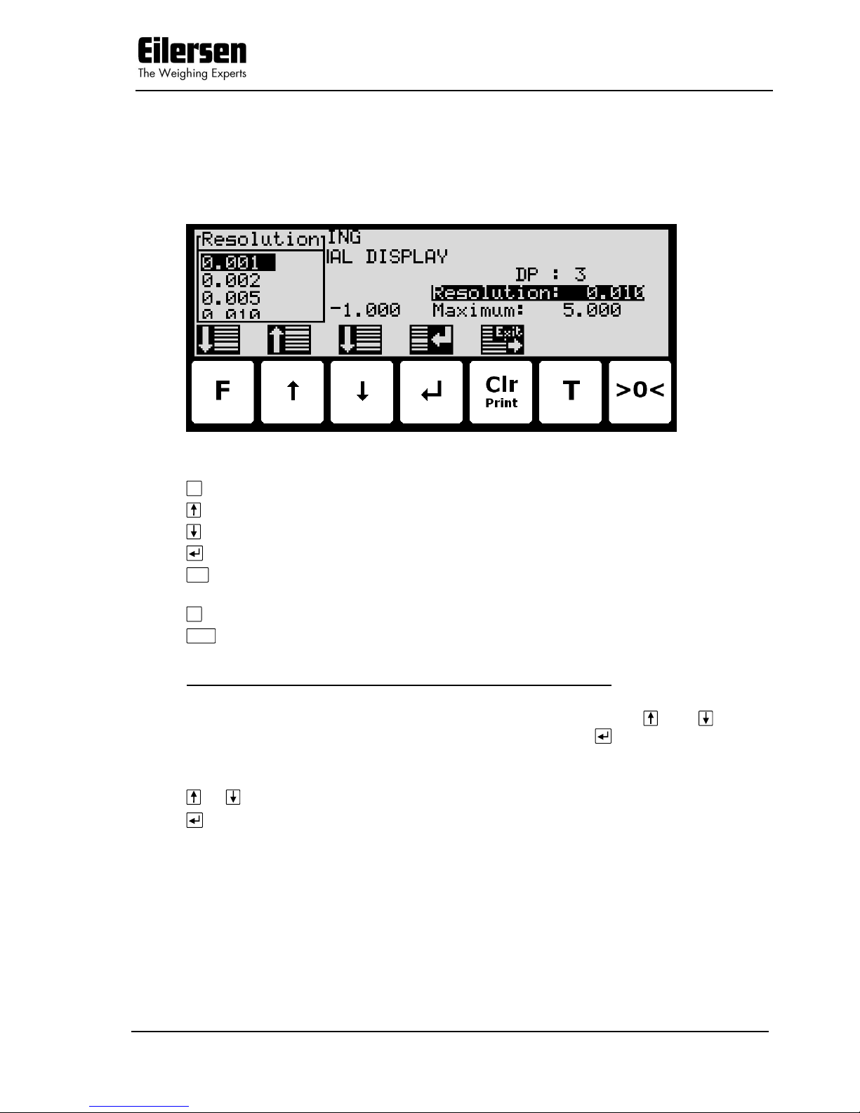
2.7.2 Entry using selection list
Some parameters (such as resolution and decimal point position of the weighing range) are entered using a selection list. When change of this type of parameter is requested, a special pull-down menu will appear with a list of predetermined (allowed) values as shown:
The keys can be used as follows:
F
Moves the cursor down in this selection list.
Moves the cursor up in this selection list.
Moves the cursor down in this selection list.
Accepts the selected/marked value as the new desired value.
Print
Clr
Aborts the entry without change of parameter. This can also be
done by selecting the “CANCEL” entry form the selection list.
T
Not used.
>0<
Not used.
Example - Changing resolution from 0.050 to 0.010:
The screen shown above appears once change of resolution is requested from
the SETUP WEIGHING screen by moving the cursor using and so the
“Resolution” parameter is selected and then pressing . In order to change
the “Resolution” parameter to 0.010 perform the following:
or Press repeatedly until ”0.010” is selected in the selection list.
Press to accept selection.
5024 STDLIM.140630.2v0: Users guide
WWW.EILERSEN.COM
Version: 2017-04-05, rev.: 2v0 Page: 9
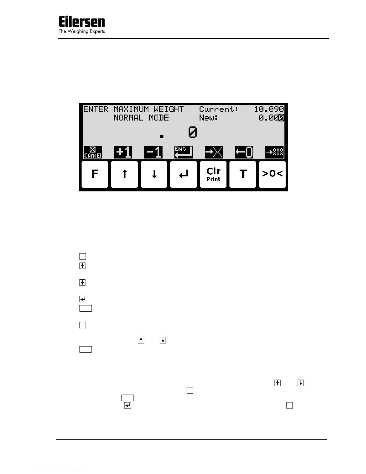
2.7.3 Entry of numbers
Some parameters (such as minimum and maximum weight of the weighing
range) are entered using a data entry screen. When change of this type of parameter is requested, a data entry screen will appear. Please note the layout
of the data entry screen may vary slightly depending on the actual parameter
to be changed. The data entry screen could look as shown:
The actual parameter changed is indicated in the upper left part of the display.
The current parameter value and the currently entered value is shown in the
upper right part of the display. The currently entered value is also shown in
the middle of the display in large font.
The keys can be used as follows:
F
Aborts the entry without change of parameter.
Increases the value of the digit currently being entered (digit to
the right).
Decreases the value of the digit currently being entered (digit to
the right).
Accepts the entered value as the new desired value.
Clr
Deletes most right digit and moves all remaining digits one posi-
tion to the right.
T
Moves digits one position to the left and inserts a zero on the
most right position. This new digit can subsequently be changed
using and .
>0<
Clears all entered digits setting them to zero as if the data entry
screen has just been entered.
When entering a value the digits are entered left to right. This means that
leftmost digit is entered first. The active digit is changed by and . When
the correct value is entered press T to advance to the next digit. If an error is
made, press
Clr
to return to the previous digit. When the complete value is
entered press to accept it. To abort without any changes press F.
5024 STDLIM.140630.2v0: Users guide
WWW.EILERSEN.COM
Version: 2017-04-05, rev.: 2v0 Page: 10
Example - Changing maximum weight from 10.000 to 10.090:
The screen shown above appears once change of maximum weight is requested from the SETUP WEIGHING screen by moving the cursor using and
so the “Maximum” weight parameter is selected and then pressing .
In order to change the “Maximum” weight parameter to 10.090 perform the
following:
Press once until ” . 1” is shown in the display.
T
Press three times until ” 1.000” is shown in the display.
Press once until ” 1.009” is shown in the display.
T
Press once until ” 10.090” is shown in the display.
Press to accept ” 10.090” as the new desired value.
Example - Changing minimum weight from -1.000 to -0.090:
A similar screen to the screen shown above appears once change of minimum
weight is requested from the SETUP WEIGHING screen by moving the cursor
using and so the “Minimum” weight parameter is selected and then
pressing .
In order to change the “Minimum” weight parameter to -0.090 perform the
following:
Press once until ”- . 9” is shown in the display.
T
Press once until ”- . 90” is shown in the display.
Press to accept ”- 0.090” as the new desired value.
Example - Changing date to 11.06.01:
A similar screen to the screen shown above appears once change of date
(YY.MM.DD) is requested from the SETUP MENU by moving the cursor using
and so the “SET DATE” entry is selected and then pressing . The layout
of the data entry screen is a bit different as date is entered with two decimal
points.
In order to change the date (YY.MM.DD) to 11.06.01 perform the following:
T
Press once until ” . .10” is shown in the display.
Press once until ” . .11” is shown in the display.
T
Press two times until ” .11.01” is shown in the display.
Press four times until ” .11.06” is shown in the display.
T
Press two times until ”11.06.01” is shown in the display.
Press to accept ”11.06.01” as the new desired value.
Example - Changing time to 23:45:00:
A similar screen to the screen shown above appears once change of time
(HH:MM:SS) is requested from the SETUP MENU by moving the cursor using
and so the “SET TIME” entry is selected and then pressing . The layout
of the data entry screen is a bit different as time is entered with two colons.
5024 STDLIM.140630.2v0: Users guide
WWW.EILERSEN.COM
Version: 2017-04-05, rev.: 2v0 Page: 11
In order to change the time (HH:MM:SS) to 23:45:00 perform the following:
Press two times until ” : : 2” is shown in the display.
T
Press once until ” : :20” is shown in the display.
Press three times until ” : :23” is shown in the display.
T
Press once until ” : 2:30” is shown in the display.
Press four times until ” : 2:34” is shown in the display.
T
Press once until ” :23:40” is shown in the display.
Press five times until ” :23:45” is shown in the display.
Press to accept ”23:45:00” as the new desired value.
Example – Entry of IP address 192.168.001.199:
A similar screen to the screen shown above appears once change of IP address
is requested from the SETUP ETHERNET screen by moving the cursor using
and so the “IP” parameter is selected and then pressing . The layout of
the data entry screen is a bit different as IP address is entered with three decimal points.
Please note: Subnet is entered in same way as IP address.
Please note: Due to IP address and subnet requirements not all values are
allowed.
In order to change the IP address parameter to 192.168.001.199 perform the
following:
Press once until ” . . . 1” is shown in the display.
T
Press once until ” . . . 10” is shown in the display.
Press once until ” . . . 19” is shown in the display.
T
Press once until ” . . .190” is shown in the display.
Press two times until ” . . .192” is shown in the display.
T
Press once until ” . . 1.920” is shown in the display.
Press once until ” . . 1.921” is shown in the display.
T
Press once until ” . . 19.210” is shown in the display.
Press four times until ” . . 19.216” is shown in the display.
T
Press once until ” . .192.160” is shown in the display.
Press two times until ” . .192.168” is shown in the display.
T
Press three times until ” .192.168.000” is shown in the display.
Press once until ” .192.168.001” is shown in the display.
T
Press once until ” 1.921.680.010” is shown in the display.
Press once until ” 1.921.680.011” is shown in the display.
T
Press once until ” 19.216.800.110” is shown in the display.
Press once until ” 19.216.800.119” is shown in the display.
T
Press once until ”192.168.001.190” is shown in the display.
Press once until ”192.168.001.199” is shown in the display.
Press to accept ”192.168.001.199” as the new desired value.

5024 STDLIM.140630.2v0: Users guide
WWW.EILERSEN.COM
Version: 2017-04-05, rev.: 2v0 Page: 12
3) Screens
The following is a description of each available screen and the active keys in
each screen.
3.1 Normal display
Below the NORMAL screen is shown along with the keys that are enabled.
In this screen the actual weight is shown with large types. To the right the unit
is indicated and whether the gross or net weight is shown. If the load is above
the weighing range the display will show OL. If the load is below the weighing
range the display will show UL. If an error is present an error code will be
shown (-XXXX-) instead of the weight reading. Above the actual setpoint
(fine limit) is shown. Above
Print
Clr
the last registered weight is shown in paren-
thesis. Also above
Print
Clr
an “OK” icon is shown for a short period following every
successful registration. In the upper right corner four symbols may be shown
below each other indicating:
‘>0<’ if the weight is zero (within 0 ± ¼ division).
‘––’ if the weight reading is steady, or ‘~’ if the weight reading is not
steady.
‘ZT’ if automatic zeroing (zero tracking) is active (within 0 ± ½ division).
‘SP’ if automatic dosing is running.
‘R’ if registration is in progress.
Note: If the keyboard is locked the symbols above the keys will not be shown.
5024 STDLIM.140630.2v0: Users guide
WWW.EILERSEN.COM
Version: 2017-04-05, rev.: 2v0 Page: 13
If the keyboard is not locked, the keys are used as follows:
F
Selects the MAIN menu.
Selects the DOSING screen for entry of setpoints and start/stop
of dosing.
Display weight with enhanced resolution for 3 seconds (in the
SYSTEM screen it can be selected that enhanced resolution is
toggle permanently on/off for test purposes). The “Dd/10” symbol
above the key will blink when enhanced resolution is selected.
Toggles between gross and net reading.
Print
Not used.
T
Zeroes the net reading and net reading is selected.
>0<
Zeroes the gross reading and gross reading is selected.
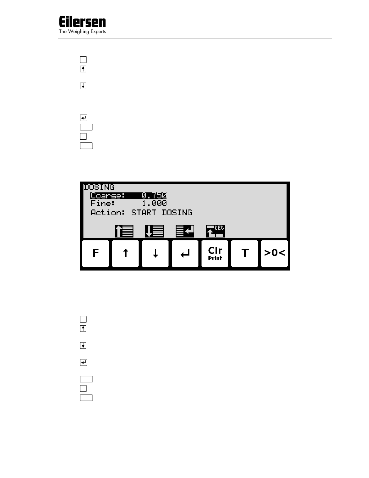
3.2 Dosing
Below the DOSING screen is shown along with the keys that are enabled.
In this screen setpoints for dosing are shown and can be changed. It is also
possible to start/stop a dosing. A cursor (inverted text) indicates the currently
selected parameter.
The keys are used as follows:
F
Not used.
Moves the cursor up between the different parameters on the
screen.
Moves the cursor down between the different parameters on the
screen.
Selects change/entry of the parameter marked/selected by the
cursor.
Clr
Return to the NORMAL screen.
T
Not used.
>0<
Not used.
Please note that some other dosing parameters (such as registration period
and afterflow correction) are configured in the DOSING PAR. screen.

5024 STDLIM.140630.2v0: Users guide
WWW.EILERSEN.COM
Version: 2017-04-05, rev.: 2v0 Page: 14
To perform an automatic dosing, follow this procedure:
1. The desired Coarse and Fine setpoints must be entered. Use the key
in the NORMAL screen to select the DOSING screen. Then use the
DOSING screen to enter the desired setpoints.
2. To start a new dosing select the “Action: START DOSING” using the
or key in the DOSING screen and then press the key. Alternately
start a new dosing by activating the digital START input.
3. This will zero the net weight (automatic tare) and activate the digital
COARSE and FINE dosing outputs.
4. During dosing the COARSE output is active as long as the net weight
does not exceed the COARSE limit. An active COARSE output indicates
dosing should be done at high speed for the first part of the dosing, followed by slow speed for the final part of the dosing where the COARSE
output is deactivated.
5. When the net weight (positive or negative) reaches the FINE setpoint
(possibly adjusted by the afterflow correction) the FINE output will be
deactivated and dosing is stopped.
6. Hereafter the COARSE and FINE outputs will remain deactivated until a
new dosing is started.
7. The dosed amount is automatically registered after the entered registra-
tion period, if the registration period is different from 0 ms. In this case
a registration can be made by activating the REGISTRATION input.
The result of the last registration can be read in the NORMAL screen.
8. Following a registration the totals are updated and a possible new after-
flow correction may be calculated.
9. An ongoing dosing can be stopped prior to reaching the setpoint, by se-
lecting the “Action: STOP DOSING” using the or key in the DOS-
ING screen and then pressing the key. An ongoing dosing is also
aborted if the weighing range is exceeded or if a loadcell error occurs.
10. The weighing terminal is ready for start of a new dosing.
3.2.1 Setting Coarse and Fine limits
The COARSE and FINE setpoints used for automatic dosing must be specified
in the DOSING screen.
The COARSE limit is used to control the COARSE output indicating high speed
dosing until the COARSE setpoint is reached. The FINE limit is used to control
the FINE output indicating the desired amount to be dosed. The setpoints are
changed by using and to select the desired setpoint (“Coarse” or “Fine”)
with the cursor, and then pressing to request change of the setpoint.
3.2.2 Start/Stop of dosing
In addition to starting a dosing using the digital START input, a dosing can be
started (or stopped if a dosing is all ready in progress) using the keyboard in
the DOSING screen.
A dosing is started or stopped by using and to select the “Action” parameter with the cursor, and then pressing to request the indicated action
(“START DOSING” or “STOP DOSING”).
5024 STDLIM.140630.2v0: Users guide
WWW.EILERSEN.COM
Version: 2017-04-05, rev.: 2v0 Page: 15
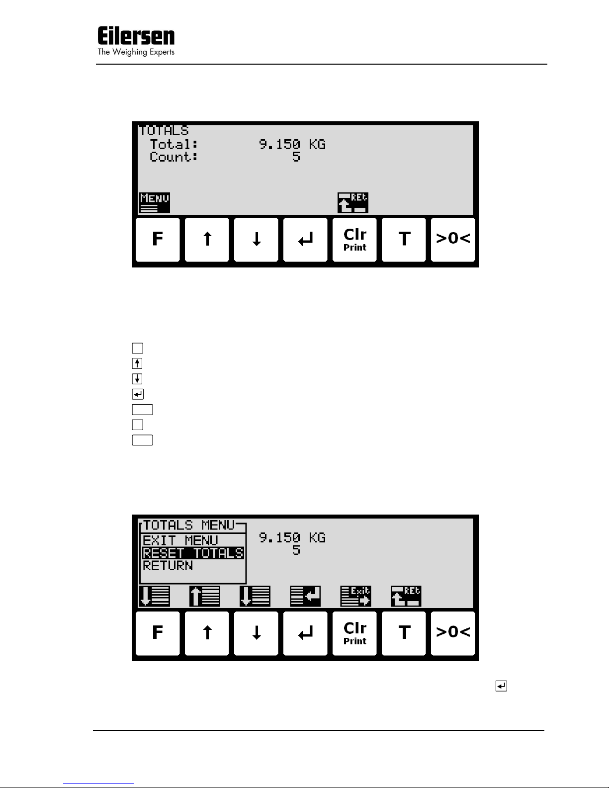
3.3 Totals
Below the TOTALS screen is shown along with the keys that are enabled.
In this screen the totals are shown. Whenever a registration is performed the
total weight is updated with the registered amount and the total count is incremented.
The keys are used as follows:
F
Selects the TOTALS MENU.
Not used.
Not used.
Not used.
Clr
Return to the NORMAL screen.
T
Not used.
>0<
Not used.
3.3.1 Totals menu
When the TOTALS MENU is invoked the screen will look like this:
To reset the totals select the “RESET TOTALS” menu item and press .
5024 STDLIM.140630.2v0: Users guide
WWW.EILERSEN.COM
Version: 2017-04-05, rev.: 2v0 Page: 16
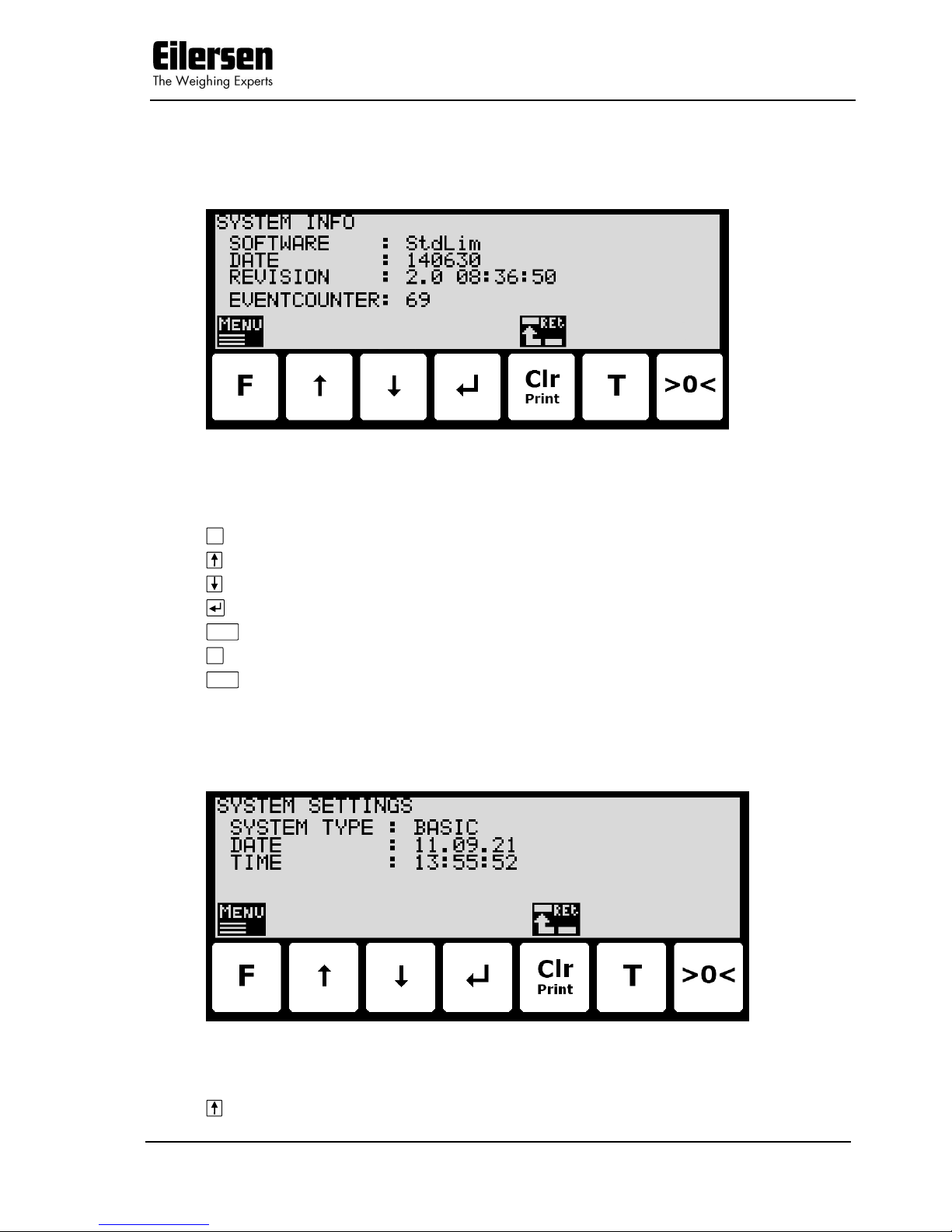
3.4 System Information
Below the SYSTEM INFO screen is shown along with the keys that are enabled.
In this screen program identification (consisting of software name, date and
revision) and the event counter is shown.
The keys are used as follows:
F
Selects the INFO menu.
Not used.
Not used.
Not used.
Clr
Return to the NORMAL screen.
T
Not used.
>0<
Not used.
3.5 System settings
Below the SYSTEM SETTINGS screen is shown along with the keys that are
enabled.
In this screen the system type is shown along with the current date and time.
The keys are used as follows:
Not used.
5024 STDLIM.140630.2v0: Users guide
WWW.EILERSEN.COM
Version: 2017-04-05, rev.: 2v0 Page: 17
Not used.
Not used.
Clr
Return to the NORMAL screen.
T
Not used.
>0<
Not used.
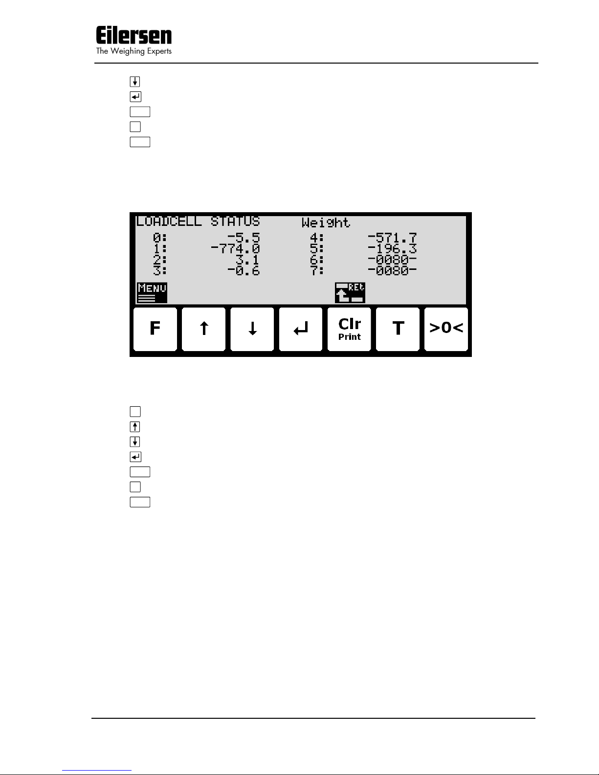
3.6 Loadcell status
Below the LOADCELL STATUS screen is shown along with the keys that are
enabled.
In this screen the actual reading from each loadcell is shown.
The keys are used as follows:
F
Selects the LOADCELL STATUS menu.
Not used.
Not used.
Not used.
Clr
Return to the SYSTEM INFO screen.
T
Not used.
>0<
Not used.
Three different readings can be selected with the menu:
DIRECT: The internal loadcell output value is displayed as it is received.
This number is in SI units, but the resolution is loadcell dependent and may be an unusual value like 100mg, 10 gr. etc.
Furthermore no zeroing is used and the loadcell value will NOT
be 0 when the loadcell is empty, so this value is not the absolute load on this loadcell
WEIGHT: The loadcell output value in the resolution etc., selected for the
display. No zeroing is used and the loadcell value will NOT be 0
when the loadcell is empty, so this value is not the absolute
load on this loadcell.
ZEROED: The loadcell output value in the resolution etc., selected for the
display. The value is zeroed along with the normal display
reading. So this value is the change since the last zeroing.
5024 STDLIM.140630.2v0: Users guide
WWW.EILERSEN.COM
Version: 2017-04-05, rev.: 2v0 Page: 18
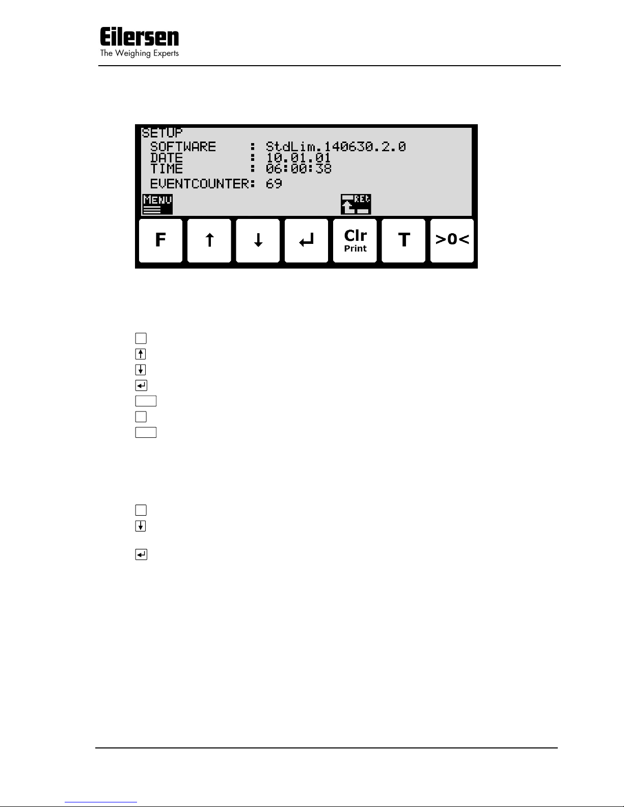
3.7 Service mode
Below the SETUP screen is shown along with the keys that are enabled.
In this screen the software version, actual date, actual time and event counter
is shown.
The keys are used as follows:
F
Selects the SETUP menu.
Not used.
Not used.
Not used.
Clr
Return to the NORMAL screen.
T
Not used.
>0<
Not used.
3.7.1 Setting date and time
It is possible to set the date and/or time of the internal clock by use of the
SETUP menu. To set date and/or time from the SETUP screen perform the
following:
F
Press once to select the SETUP menu.
Press several times to select the “SET DATE” or “SET TIME” entry
from the SETUP menu.
Press once to start entry of the selected parameter (date or
time).
5024 STDLIM.140630.2v0: Users guide
WWW.EILERSEN.COM
Version: 2017-04-05, rev.: 2v0 Page: 19
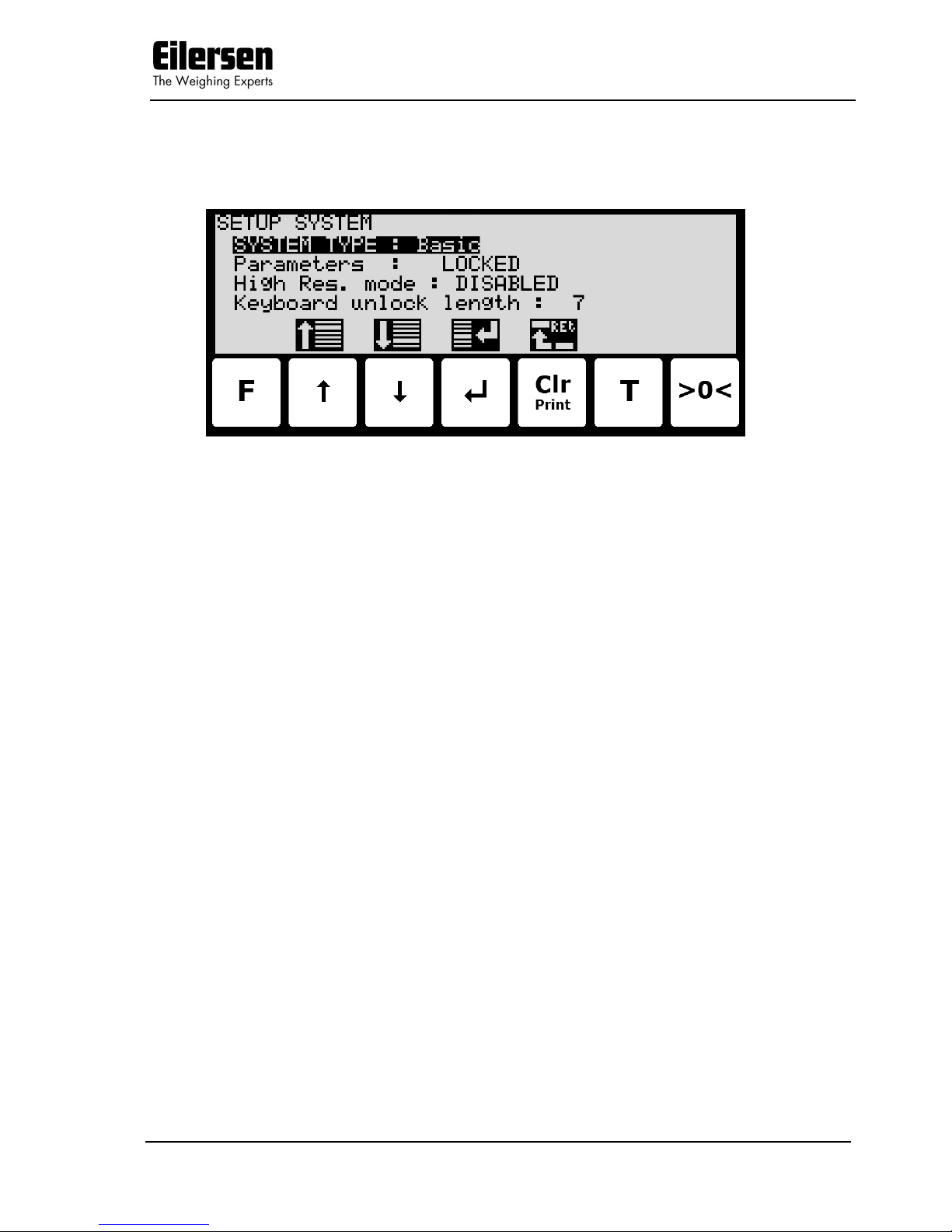
3.8 System
Below the SETUP SYSTEM screen is shown along with the keys that are enabled.
In this screen the system parameters are shown and can be changed. A cursor
(inverted text) indicates the currently selected parameter.
The following parameters are accessible:
SYSTEME TYPE: For this software only “Basic” system type can be chosen.
Parameters: When the power is turned on all parameters changing the
event counter are locked. Change this setting to “UN-
LOCKED” to access the parameters. Before unlocking is
possible the password 1357 must be entered. The setting
automatically returns to ”LOCKED” after 5 minutes without keyboard activity in NORMAL screen.
High Res. Mode: When this setting is enabled the “Dd/10” key in the
NORMAL toggles the enhanced resolution on and off
permanently. When the setting is disabled the “Dd/10”
key in the NORMAL toggles the enhanced resolution on
for 3 seconds.
Keyb. unlock leng.: With this setting set to 0, the keyboard lock feature is dis-
abled. With this setting set to other values (1-50; default
value is 7), the keyboard lock feature is enabled. The parameter then indicates the length of the key sequence
that must be pressed to unlock a locked keyboard.
5024 STDLIM.140630.2v0: Users guide
WWW.EILERSEN.COM
Version: 2017-04-05, rev.: 2v0 Page: 20
The keys are used as follows:
F
Not used.
Moves the cursor up between the different parameters on the
screen.
Moves the cursor down between the different parameters on the
screen.
Selects change/entry of the parameter marked/selected by the
cursor.
Clr
Return to the SETUP screen.
T
Not used.
>0<
Not used.
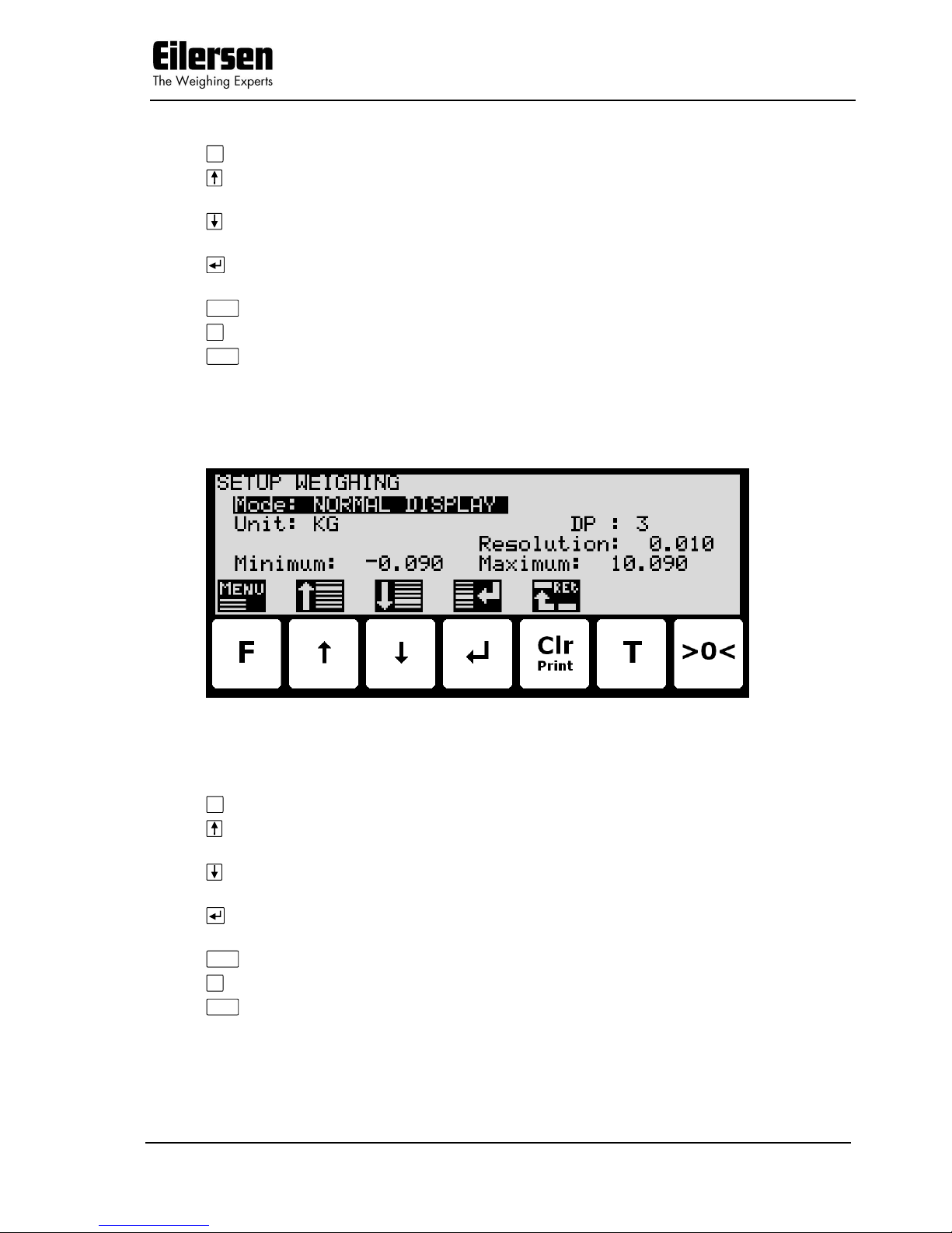
3.9 Weighing
Below the SETUP WEIGHING screen is shown along with the keys that are
enabled.
In this screen weighing parameters are shown and can be changed. A cursor
(inverted text) indicates the currently selected parameter.
The keys are used as follows:
F
Selects the WEIGHING menu.
Moves the cursor up between the different parameters on the
screen.
Moves the cursor down between the different parameters on the
screen.
Selects change/entry of the parameter marked/selected by the
cursor.
Clr
Return to the SETUP screen.
T
Not used.
>0<
Not used.
5024 STDLIM.140630.2v0: Users guide
WWW.EILERSEN.COM
Version: 2017-04-05, rev.: 2v0 Page: 21
3.9.1 Weighing range modes
The weighing terminal is equipped with three different weighing range modes
that specify the weighing range used for:
NORMAL: weight readings during normal display reading.
CALIBRATION: weight readings during calibration and enhanced
resolution weight display.
PROTOCOL: weight readings transferred using serial communi-
cation.
The weighing range mode can be selected from the SETUP WEIGHING
screen. The weighing range mode is changed by using and to select the
“Mode” parameter with the cursor, and then pressing to request change of
the “Mode” parameter using a selection list as described earlier.
When configuring weighing ranges as described below, values shown as well
as changes made only apply to the currently selected weighing range specified
by the “Mode” parameter.
3.9.2 Configuring weighing ranges
An appropriate weighing range can be configured from the SETUP WEIGHING screen. A specific weighing range is changed by using and to select
a weighing range parameter with the cursor, and then pressing to request
change of the given parameter. The following weighing range parameters need
to be configured individually for each of the three specific weighing range
modes (NORMAL, CALIBRATION and PROTOCOL):
1) “Unit” entered using a selection list as described earlier.
2) “DP” entered using a selection list as described earlier.
3) “Resolution” entered using a selection list as described earlier.
4) “Minimum weight” entered using data entry screen as described earlier.
5) “Maximum weight” entered using data entry screen as described earlier.
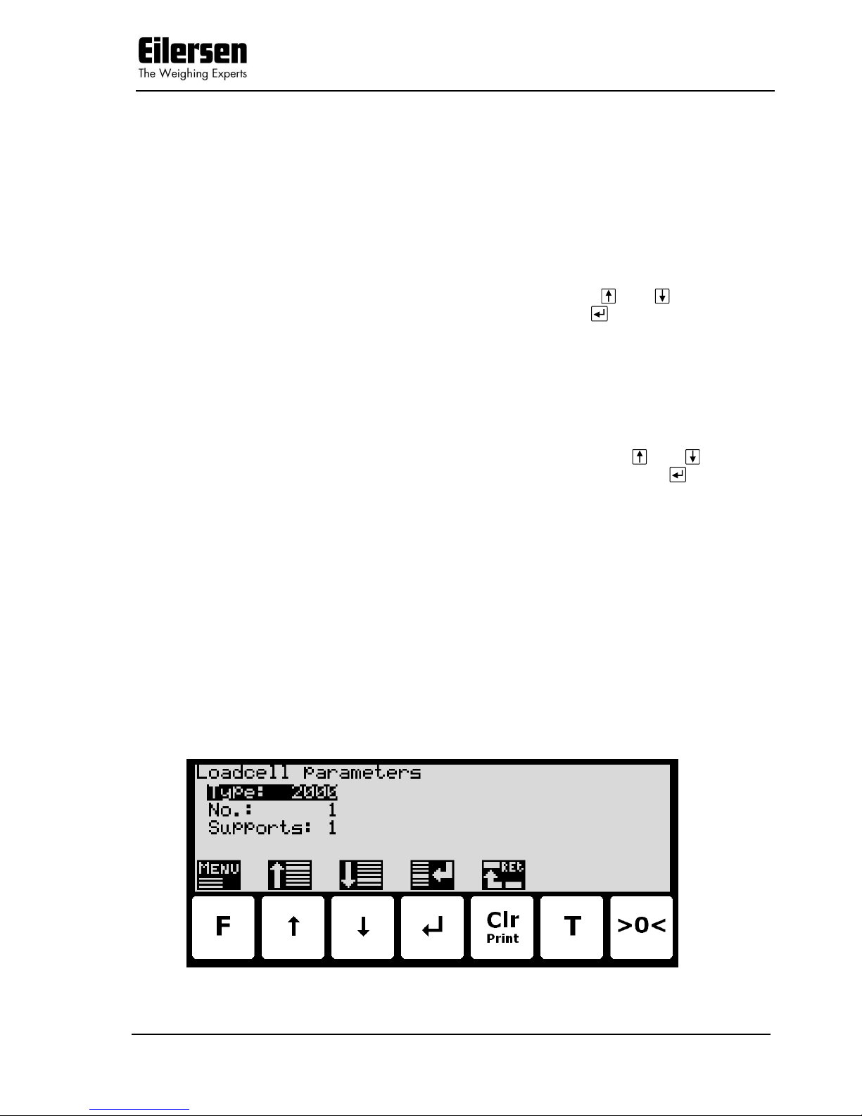
3.10 Loadcell parameters
Below the LOADCELL PARAMETERS screen is shown along with the keys that
are enabled.

5024 STDLIM.140630.2v0: Users guide
WWW.EILERSEN.COM
Version: 2017-04-05, rev.: 2v0 Page: 22
In this screen loadcell parameters are shown and can be changed. A cursor
(inverted text) indicates the currently selected parameter.
The keys are used as follows:
F
Selects the WEIGHING menu.
Moves the cursor up between the different parameters on the
screen.
Moves the cursor down between the different parameters on the
screen.
Selects change/entry of the parameter marked/selected by the
cursor.
Clr
Return to the SETUP WEIGHING screen.
T
Not used.
>0<
Not used.
3.10.1 Loadcell type
The weighing terminal can be connected to and communicate with different
kinds of loadcells from Eilersen Electric. The weighing terminal can communicate with the following loadcells:
- Eilersen Electric loadcell type 2000
- Eilersen Electric loadcell type 4000
The type of loadcell connected to the weighing terminal must be specified in
the LOADCELL PARAMETERS screen. The loadcell type indication is changed
by using and to select the “Type” parameter with the cursor, and then
pressing to request change of the loadcell “Type” parameter using a selection list as described earlier.
3.10.2 Number of loadcells
The weighing terminal can be connected to a maximum of 8 loadcells. The actual number of loadcells connected to the weighing terminal must be specified
in the LOADCELL PARAMETERS screen. The number of loadcells indication is
changed by using and to select the “No.” parameter with the cursor, and
then pressing to request change of the “No.” of loadcells parameter.
3.10.3 Number of supports
The actual number of supporting points (1-8) in the weighing system must be
specified in the LOADCELL PARAMETRS screen. The number of supporting
points indication is changed by using and to select the “Supports” parameter with the cursor, and then pressing to request change of the number of “Supports” parameter.
Note that it is the total number of supporting points including corners supported by loadcells. As an example, the “Supports” parameter should be 3 in a
system consisting of a three legged tank.
5024 STDLIM.140630.2v0: Users guide
WWW.EILERSEN.COM
Version: 2017-04-05, rev.: 2v0 Page: 23
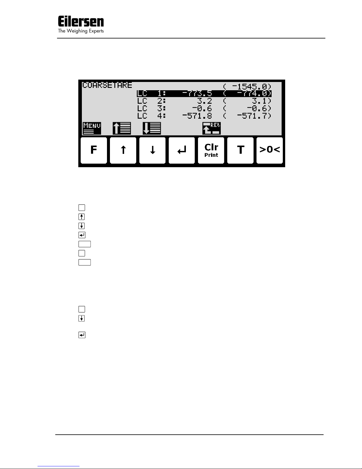
3.11 Coarsetare
Below the COARSETARE screen is shown along with the keys that are enabled.
In this screen the coarsetare values and actual signals for each loadcell is
shown.
The keys are used as follows:
F
Selects the COARSETARE menu.
Selects the next coarsetare value
Selects the previous coarsetare value
Not used.
Clr
Return to the WEIGHING screen.
T
Not used.
>0<
Not used.
3.11.1 Performing coarsetare
It is possible to coarsetare the system by use of the COARSETARE menu. To
perform a coarsetare from the COARSETARE screen perform the following:
F
Press once to select the COARSETARE menu.
Press once to select the “PERFORM COARSETARE” entry from the
COARSETARE menu.
Press once to perform the coarsetare.

5024 STDLIM.140630.2v0: Users guide
WWW.EILERSEN.COM
Version: 2017-04-05, rev.: 2v0 Page: 24
3.12 Zeroing
Below the ZEROING screen is shown along with the keys that are enabled.
This screen is used to enter the zero tracking (autozero) range.
The keys are used as follows:
F
Selects the ZEROING menu.
Moves the cursor up between the different parameters on the
screen.
Moves the cursor down between the different parameters on the
screen.
Selects change/entry of the parameter marked/selected by the
cursor.
Clr
Return to the WEIGHING screen.
T
Not used.
>0<
Not used.
3.13 Calibration
Below the CALIBRATION screen is shown along with the keys that are enabled.

5024 STDLIM.140630.2v0: Users guide
WWW.EILERSEN.COM
Version: 2017-04-05, rev.: 2v0 Page: 25
In this screen calibration parameters such as calibration factor, calibration load
(to the left) and actual gross weight (to the right) are shown and can be
changed. This makes it possible to calibrate the system. From the CALI-
BRATE menu it is possible to select the CORNER CALIBRATION screen for
corner calibration of the system. A cursor (inverted text) indicates the currently selected parameter.
The keys are used as follows:
F
Selects the CALIBRATE menu.
Moves the cursor up between the different parameters on the
screen.
Moves the cursor down between the different parameters on the
screen.
Selects change/entry of the parameter marked/selected by the
cursor.
Clr
Return to the SETUP WEIGHING screen.
T
Not used.
>0<
Zeroes the gross reading shown to the right in the “Load” line.
3.13.1 Calibration factor
The actual system calibration factor can be changed/specified in the CALIBRATION screen by performing a calibration of the system as described be-
low or by manually entering a new factor.
The calibration factor indication can be manually changed by using and to
select the “FACTOR” parameter with the cursor, and then pressing to re-
quest change of the calibration “FACTOR” parameter. This is useful when a
previous calibration must be re-established. Note that this is only possible, if
the calibration factor for this previous calibration is known. The standard calibration factor is 524288. If this value is changed 1% (up or down), the gross
weight indication will also change 1% (up or down).
3.13.2 Calibration load
The actual mass of the load used for calibration must be specified in the CALIBRATION screen before calibration is performed. The calibration load indica-
tion is changed by using and to select the “LOAD” parameter with the
cursor, and then pressing to request change of the calibration “LOAD” parameter.
3.13.3 Perform calibration
It is possible to calibrate the system by performing the following calibration
procedure (assuming the system has previously been coarsetared and possibly
corner calibrated):
Ensure the weighing scale is empty and clean.
>0<
Press once to zero the gross reading of the empty weighing scale.
Press repeatedly until “LOAD” parameter is selected with the cur-
sor.
Press once to start entry of the actual calibration load if neces-
sary. Please notice that the accuracy of the calibration is deeply
dependent on the accuracy and size of the calibration load. Please

5024 STDLIM.140630.2v0: Users guide
WWW.EILERSEN.COM
Version: 2017-04-05, rev.: 2v0 Page: 26
select a load with a mass not less than the maximum weight
normally applied to the system.
Place the load on the weighing arrangement. The gross weight of
the load displayed to the far right in the “LOAD” line will now be
inside +/- 10% of the correct reading. If this isn’t the case the
mechanical and electrical installation must be checked. Furthermore all weighing range parameters must be checked again.
F
Press once to select the CALIBRATE menu.
Press once to select the “PERFORM CALIBRATION” entry from the
CALIBRATE menu.
Press once to perform the calibration.
The gross weight shown in the display will now match the used
calibration load and the calibration factor will have been updated
correspondingly.
3.13.4 Corner calibration
Below the CORNER CALIBRATION screen is shown along with the keys that
are enabled.
In this screen corner calibration parameters such as corner calibration factor,
and actual load on corresponding loadcell is shown on one line for each
loadcell. The actual gross weight is shown in the upper right corner. This
makes it possible to manually enter the corner calibration factor for each
loadcell. From the CORNER CAL. menu it is possible to select the CORNER
CAL. PROC. screen for corner calibration of the system. It is also possible to
reset the corner calibration factors to default values from the menu. A cursor
(inverted text) indicates the currently selected parameter.
The keys are used as follows:
F
Selects the CALIBRATE menu.
Moves the cursor up between the different parameters on the
screen.
Moves the cursor down between the different parameters on the
screen.
Selects change/entry of the parameter marked/selected by the
cursor.

5024 STDLIM.140630.2v0: Users guide
WWW.EILERSEN.COM
Version: 2017-04-05, rev.: 2v0 Page: 27
Clr
Return to the CALIBRATION screen.
T
Not used.
>0<
Zeroes the gross reading shown in the upper right corner.
3.13.5 Corner calibration factor
The corner calibration factors can be changed/specified in the CORNER CALIBRATION screen by performing a calibration of the corners by switching to
the CORNER CAL. PROC. screen as described below or by manually entering a
new factor.
The corner calibration factors can be manually changed by using and to
select the desired loadcell/corner with the cursor, and then pressing to request change of the selected corner calibration “FACTOR” parameter. This is
useful when a previous calibration must be re-established. Note that this is only possible, if the calibration factor for this previous calibration is known. The
standard calibration factor is 524288. If this value is changed 1% (up or
down), the signal from that loadcell/corner will also change 1% (up or down).
3.13.6 Reset corner calibration factors
It is possible to reset the corner calibration factors to default values (524288)
by using the CORNER CAL. menu. To perform a reset of corner calibration
factors from the CORNER CALIBRATION screen perform the following:
F
Press once to select the CORNER CAL. menu.
Press once to select the “RESET CORNER CAL. FACTORS” entry
from the CORNER CAL. menu.
Press once to perform the reset of the corner calibration factors.
3.13.7 Corner calibration procedure
It is possible to perform an automatic corner calibration of the system by selecting the CORNER CALIBRATION PROCEDURE screen from the CORNER
CAL. menu. Below the CORNER CALIBRATION PROCEDURE screen is
shown along with the keys that are enabled.

5024 STDLIM.140630.2v0: Users guide
WWW.EILERSEN.COM
Version: 2017-04-05, rev.: 2v0 Page: 28
In this screen a line for each loadcell will be shown indicating “NOT regis-
tered“. Once the signal resulting from a given load placed above a loadcell is
registered this indication will change to “Registered” followed by the registered
load for this loadcell/corner. The actual gross weight is shown in the upper
right corner.
The keys are used as follows:
F
Selects the CORNER CAL. PROC. menu.
Moves the cursor up between the different parameters on the
screen.
Moves the cursor down between the different parameters on the
screen.
Selects change/entry of the parameter marked/selected by the
cursor.
Clr
Return to the CORNER CALIBRATION screen.
T
Not used.
>0<
Zeroes the gross reading shown in the upper right corner.
To corner calibrate the system from the CORNER CALIBRATION PROCEDURE
screen the following procedure (assuming the system has previously been
coarsetared) is followed:
1) Zero the gross reading in the upper right corner by pressing
>0<
.
2) Place the used calibration load directly above one of the loadcells/corners.
3) Perform the sampling/registration of the loadcell/corner in question by
pressing the key. The weighing terminal will automatically detect above
which loadcell/corner the load is actually placed and register the corresponding signal. The registered value is indicated on the screen and the
status is changed from ”NOT registered” to ”Registered”.
4) Remove the calibration load. Zero the weight reading if necessary by press-
ing
>0<
before the load is placed above a new loadcell/corner.
5) Repeat 2-4 for each loadcell/corner in the system as the calibration load is
moved to a new loadcell/corner each time. It is important that 2-4 is performed for every loadcell/corner in the system. When all loadcells/corners
are registered all status indications should indicate ”Registered”.
6) The corner calibration can be restarted at any given time by selecting ”RE-
START CORNER CAL. PROC.” from the CORNER CAL. PROC. menu or by
leaving the CORNER CALIBRATION PROCEDURE screen.
7) Once all loadcells/corners have been sampled/registered the corner calibra-
tion itself can be performed. This is done by selecting ”PERFORM CORNER
CAL.” from the CORNER CAL. PROC. menu. IMPORTANT: Until this is
done the corner calibration is NOT performed and the corner calibration
factors will remain unchanged.
8) The corner calibration will now be performed based on the sampled values,
and the weighing terminal returns to the CORNER CALIBRATION screen.

5024 STDLIM.140630.2v0: Users guide
WWW.EILERSEN.COM
Version: 2017-04-05, rev.: 2v0 Page: 29
9) Following the corner calibration it should be verified that the corner calibra-
tion factors are reasonable values. It should also be checked that identical
weight readings are achieved when the calibration load is placed above
each of the loadcells/corners. NOTE: The calibration load parameter from
the CALIBRATION screen is not used during corner calibration; instead
the corner calibration procedure will result in a gross reading of approximately the average value of the registered loadcell/corner values.
3.14 Linearization
Below the LINEARIZATION screen is shown along with the keys that are enabled.
In this screen linearization parameters are shown and can be changed in order
to compensate for hysteresis etc. in the weighing system. In the lower half of
the screen just above the key icons the selected linearization point number,
the entered load for this point and the up/down corrections (added/subtracted) for this point are shown. Just above this in the upper half of
the screen the actual used interval, the corrected gross weight, the uncorrected gross weight, the corrected “filtered” gross weight and the direction is
shown. In the upper right corner the hysteresis limit is shown. A cursor (inverted text) indicates the currently selected parameter.
NOTE: This screen is normally NOT used, and should only be used in weighing
systems where system mechanics shows non ideal behavior.
The keys are used as follows:
F
Selects the LINEARIZATION menu.
Moves the cursor up between the different parameters on the
screen.
Moves the cursor down between the different parameters on the
screen.
Selects change/entry of the parameter marked/selected by the
cursor.
Clr
Return to the SETUP WEIGHING screen.
T
Moves the cursor right to the next parameter column on the
screen.
>0<
Zeroes the gross reading.

5024 STDLIM.140630.2v0: Users guide
WWW.EILERSEN.COM
Version: 2017-04-05, rev.: 2v0 Page: 30
3.14.1 Load points
The load points in which the given corrections are performed must be specified
in the LINEARIZATION screen. The load points are changed by using and
to select the desired point number in the “Load” column with the cursor,
and then pressing to request change of the selected load parameter.
The load parameters must be entered in rising order; i.e. starting with 0kg for
point no. 0 and always rising upwards for rising point numbers. It must be ensured all load points including the up/down corrections are valid.
3.14.2 Up/Down corrections
The up/down corrections performed in the different load points must be specified in the LINEARIZATION screen. The up/down corrections are changed by
using and to select the desired point number in the “UP-cor” or “DOWNcor” column with the cursor, and then pressing to request change of the selected up/down correction parameter.
Note that UP corrections are added while DOWN corrections are subtracted.
3.14.3 Hysteresis limit
The hysteresis limit must be specified in the LINEARIZATION screen. The
hysteresis limit specifies the weight change in a given direction that must take
effect for a direction change to be detected. The hysteresis limit is changed by
using and to select the hysteresis limit parameter with the cursor, and
then pressing to request change of the hysteresis limit parameter.
3.14.4 Reset linearization
The entered linearization (load points and up/down corrections) can be reset
(setting load points to default values and up/down corrections to 0) by using
the LINEARIZATION menu. To perform a reset of linearization from the
LINEARIZATION screen perform the following:
F
Press once to select the LINEARIZATION menu.
Press once to select the “RESET LINEARIZATION” entry from the
LINEARIZATION menu.
Press once to perform the reset of the linearization parameters.

5024 STDLIM.140630.2v0: Users guide
WWW.EILERSEN.COM
Version: 2017-04-05, rev.: 2v0 Page: 31
3.15 Weight display
Below the WEIGHT DISPLAY screen is shown along with the keys that are
enabled.
In this screen weight display parameters are shown and can be changed. A
cursor (inverted text) indicates the currently selected parameter.
The keys are used as follows:
F
Not used.
Moves the cursor up between the different parameters on the
screen.
Moves the cursor down between the different parameters on the
screen.
Selects change/entry of the parameter marked/selected by the
cursor.
Clr
Return to the SETUP WEIGHING screen.
T
Not used.
>0<
Not used.
3.15.1 Interval
The interval between each update of the weight indication must be specified in
the WEIGHT DISPLAY screen. The interval indication is changed by using
and to select the “Interval” parameter with the cursor, and then pressing
to request change of the display “Interval” parameter.
The interval (measuring time) is entered in milliseconds (ms). A small value
results in fast update of the display reading, while a larger value results in a
more steady display reading. A good starting/default value is 400 ms.

5024 STDLIM.140630.2v0: Users guide
WWW.EILERSEN.COM
Version: 2017-04-05, rev.: 2v0 Page: 32
3.15.2 Filters
Two types of filters can be applied: A filter on each sampling from the loadcell
and/or a filter on each display weight reading update. The sampling frequency
depends on the types and number of loadcells and the weight display reading
update rate, as described below (Section 7.1 Appendix A: Filters). The weight
display reading update rate is selected in the WEIGHT DISPLAY screen as
described above. The filter selections are changed by using and to select
the “Filters - Sample” and “Filters - Display” parameter with the cursor, and
then pressing to invoke a filter selection list. The filter selections list will indicate the possible filter taps and damping; the filter frequency depends on
the sampling/update rate.
Please see below (Section 7.1 Appendix A: Filters) for details on filter specifications.
3.15.3 Steady/stability detection
The weight is considered stable when the readings are within the limit entered
here. The weight ready used for steady detection is filtered with the filter entered here. The steady detection filter works like the display filter.
3.16 Analog output
Below the ANALOG OUTPUT screen is shown along with the keys that are
enabled.
In this screen analog output parameters are shown and can be changed. A
cursor (inverted text) indicates the currently selected parameter.
The keys are used as follows:
F
Selects the ANALOG OUTPUT menu.
Moves the cursor up between the different parameters on the
screen.
Moves the cursor down between the different parameters on the
screen.
Selects change/entry of the parameter marked/selected by the
cursor.
Clr
Return to the SETUP WEIGHING screen.
T
Not used.
>0<
Not used.

5024 STDLIM.140630.2v0: Users guide
WWW.EILERSEN.COM
Version: 2017-04-05, rev.: 2v0 Page: 33
3.16.1 Output type
The analog output type can as current: 4-20mA or voltage: 0-10V. Please notice that voltage and current outputs are assigned to two different pins. The
pin for the type not used will take a random voltage value from –15V to +15V.
The maximum load resistor for current output is 500 ohm.
3.16.2 Output value
The value used to generate the analog output can be either the current gross
weight or the current net weight.
3.16.3 Full-scale value
When the selected weight is zero, the analog output is at its minimum value
(4mA or 0V).
The maximum output value (20mA or 10V) is reached when the weight is at
the entered full-scale value.
3.16.4 Error output value
When the selected weight cannot be calculated e.g. due to loadcell not connected or loadcell error the analog output can be selected to be at the minimum value (4mA or 0V) or the maximum output value (20mA or 10V).
3.16.5 Test output
When the Test Mode is set to ON the analog is not controlled by the current
weight but by the test value entered.

5024 STDLIM.140630.2v0: Users guide
WWW.EILERSEN.COM
Version: 2017-04-05, rev.: 2v0 Page: 34
3.17 Dosing parameters
Below the DOSING PAR. screen is shown along with the keys that are enabled.
In this screen dosing parameters such as registration period and afterflow correction are shown and can be changed. A cursor (inverted text) indicates the
currently selected parameter.
The keys are used as follows:
F
Not used.
Moves the cursor up between the different parameters on the
screen.
Moves the cursor down between the different parameters on the
screen.
Selects change/entry of the parameter marked/selected by the
cursor.
Clr
Return to the SETUP screen.
T
Not used.
>0<
Not used.
3.17.1 Registration period
The registration period, the time from a dosing has finished to the actual
amount dosed is registered automatically, must be specified in the DOSING
PAR. screen. The registration period is changed by using and to select
the “Reg. period” parameter with the cursor, and then pressing to request
change of the “Reg. period” parameter.
The registration period is entered in milliseconds (0 - 30000 ms). The value
should be set large enough to ensure no vibrations and a stable weight indication is achieved before the automatic registration is performed. A value of 0
ms indicates that NO automatic registration is performed, and that a registration must be made using the REGISTRATION input (or the keyboard).
3.17.2 Afterflow status
The afterflow status, indicating whether afterflow correction is disabled (OFF),
enabled using a fixed correction (ON) or enabled using an automatically ad-

5024 STDLIM.140630.2v0: Users guide
WWW.EILERSEN.COM
Version: 2017-04-05, rev.: 2v0 Page: 35
justed correction (AUTO), must be configured in the DOSING PAR. screen.
The afterflow status can be toggled between OFF, ON and AUTO by using
and to select the “Afterflow status” parameter with the cursor, and then
pressing until the “Afterflow status” parameter is set to the desired value.
3.17.3 Afterflow correction
The actual afterflow correction used during dosing if enabled using the “After-
flow status” parameter (ON or AUTO), is the amount prior to the net weight
reaching the FINE limit, where the dosing is assumed to be completed and the
FINE and COARSE outputs are deactivated. The “Afterflow” parameter indicates the actual correction and can be set in the DOSING PAR. screen.
The afterflow correction is changed by using and to select the “Afterflow”
parameter with the cursor, and then pressing to request change of the “Afterflow” parameter.
Please note that the “Afterflow” parameter is not used if afterflow correction is
disabled by setting the “Afterflow status” parameter to OFF.
Also note that the “Afterflow” parameter can be changed automatically after
each dosing if afterflow correction is performed automatically by setting the
“Afterflow status” parameter to AUTO.
3.18 Ethernet
The SETUP ETHERNET screen is described separately in the “ETHERNET
COMMUNICATION” chapter.
3.19 External module
An external module can be connected to the RS485 channel. This external
module can be used for Profibus-DP, PROFINET, DeviceNet or Ethernet-IP connectivity.
The EXTERNAL MODULE and EXTERNAL MODULE DATA screens are described separately in the “EXTERNAL MODULES” chapter.

5024 STDLIM.140630.2v0: Users guide
WWW.EILERSEN.COM
Version: 2017-04-05, rev.: 2v0 Page: 36
4) Ethernet communication
This chapter describes the Ethernet communication on the RJ45/Cat5 Ethernet
connector (J7) of the 5024 terminal.
For possible Ethernet-IP communication using an external 2x50 Ethernet
communication module, refer to later chapter describing external modules.
4.1 Ethernet specification
Protocol: TCP/IP to PC. Weight terminal is TCP server
Communication settings 10MB/s, Half duplex
IP-Address: Fixed (default: 192.168.1.199)
TCP Port: Selectable
Ethernet connection: RJ45/Cat5
4.1.1 Registration
Whenever a registration is made. The result is transmitted as an ASCII string
on the TCP connection. This is only done if a client is connected to the weight
terminal TCP server. Only 1 TCP connection can be opened. The transmission
format is
NNN.NNN,GGG.GGG<CR><LF>
NNN.NNN Net weight with decimal point position and resolution as in display
reading.
GGG.GGG Gross weight with decimal point position and resolution as in dis-
play reading.
<CR><LF> Carriage return and linefeed characters.
4.1.2 PC Test software
The Ethernet communication can be tested with the EEOnline software. Just
copy the .EXE and .INI file to a suitable location and run EEOnline.exe. Enter
the IP address and the port. When then PC and the 5024 is on the same network segment a connection can be established by clicking “Connect”.
4.2 Ethernet
Below the SETUP ETHERNET screen is shown along with the keys that are
enabled.

5024 STDLIM.140630.2v0: Users guide
WWW.EILERSEN.COM
Version: 2017-04-05, rev.: 2v0 Page: 37
In this screen the different Ethernet parameters are shown and can be
changed. A cursor (inverted text) indicates the currently selected parameter.
The keys are used as follows:
F
Selects the ETHERNET menu.
Moves the cursor up between the different parameters on the
screen.
Moves the cursor down between the different parameters on the
screen.
Selects change/entry of the parameter marked/selected by the
cursor.
Clr
Return to the SETUP screen.
T
Not used.
>0<
Not used.
4.2.1 Ethernet settings
Appropriate Ethernet settings can be selected from the SETUP ETHERNET
screen. Ethernet settings are changed by using and to select an Ethernet
parameter with the cursor, and then pressing “ to request change of the
given parameter. The following Ethernet parameters can be configured:
1) “IP” address entered using a data entry screen as described earlier.
2) “Subnet” mask entered using a data entry screen as described earlier.
4.3 Ethernet Protocols
Below the ETHERNET PROTOCOLS screen is shown along with the keys that
are enabled.

5024 STDLIM.140630.2v0: Users guide
WWW.EILERSEN.COM
Version: 2017-04-05, rev.: 2v0 Page: 38
In this screen the different Ethernet protocols are shown and can be changed.
A cursor (inverted text) indicates the currently selected protocol.
The keys are used as follows:
F
Not used.
Moves the cursor up between the different parameters on the
screen.
Moves the cursor down between the different parameters on the
screen.
Selects change of the protocol settings for the protocol selected.
Clr
Return to the ETHERNET screen.
T
Not used.
>0<
Not used.
4.3.1 Ethernet protocol settings
Each Ethernet protocol can be enabled or disabled. When the protocol is enabled the port-number can be entered.

5024 STDLIM.140630.2v0: Users guide
WWW.EILERSEN.COM
Version: 2017-04-05, rev.: 2v0 Page: 39
5) External modules
5.1 Introduction
The 5024G can be connected to one external communication module on its
RS485 channel. The communication module can be either a Profibus-DP,
PROFINET, DeviceNet or Ethernet module (with Ethernet-IP protocol).
With the software versions stated below installed in the external module the
external communication module can function as a slave on the AUX-bus
(RS485), where it transfers 14 input bytes from the RS485 master (5024G) to
the Profibus-DP/PROFINET/DeviceNet/Ethernet master and 14 output bytes
from the Profibus-DP/PROFINET/DeviceNet/Ethernet master to the RS485
master (5024G).
Exchange of data between master and slave is made according to the profile/protocol described below.
5.2 External module
Below the EXTERNAL MODULE screen is shown along with the keys that are
enabled.
In this screen the external module is shown and can be changed. A cursor (inverted text) indicates the currently selected module. With this version of the
software only one module can be installed.
The line with module data shows the following information:
Device Index: Always 0 with this software version.
Device Type: ------- if no external module is connected. MCExx35 if a
Profibus-DP module is connected. MCE9637 if MCE9637
DeviceNet module is connected. 2x50 if a 2x50 Ethernet
module is connected. 2070 if a 2070 PROFINET module is
connected.
Device Address: The address is the entered address plus the base address
for the module type selected

5024 STDLIM.140630.2v0: Users guide
WWW.EILERSEN.COM
Version: 2017-04-05, rev.: 2v0 Page: 40
Endian: Endian of the individual data values transferred: MSB
most significant byte first: Big endian. LSB least significant byte first: Little endian. MSB is normally used with
Profibus-DP and PROFINET while LSB is normally used
with all other types of modules.
Status: 00: Communication up and running. 80: No connection to
the module.
Error Counter: Number off errors in communication
Bytes Out: Number of bytes to be sent from the 5024G to the exter-
nal module and from there to the ProfibusDP/PROFINET/DeviceNet/Ethernet master. This is the
number of input bytes in the ProfibusDP/PROFINET/DeviceNet/Ethernet master.
Bytes In: Number of bytes to be received in the 5024G from the ex-
ternal module and transmitted from the ProfibusDP/PROFINET/DeviceNet/Ethernet master. This is the
number of output bytes in the ProfibusDP/PROFINET/DeviceNet/Ethernet master.
The keys are used as follows:
F
Not used.
Moves the cursor up between the different modules on the
screen.
Moves the cursor down between the different modules on the
screen.
Selects change of the settings for the selected module.
Clr
Return to the SETUP screen.
T
Not used.
>0<
Not used.
The following parameters can be changed for the external module:
Device Type: The following types can be selected. None if no external
module is connected. MCExx35 if a Profibus-DP module is
connected. MCE9637 if MCE9637 DeviceNet module is
connected. 2x50 if a 2x50 Ethernet module is connected.
2070 if a 2070 PROFINET module is connected.
Device Address: The address is automatically added to the base address
for the module type selected. Enter a number in the interval 0-15. With this software version where only one external module can be connected 0 is the normal address
value.
Endian: Endian of the individual data values transferred: MSB
most significant byte first: Big endian. LSB least significant byte first: Little endian. MSB is normally used with
Profibus-DP and PROFINET while LSB is normally used
with all other types of modules.

5024 STDLIM.140630.2v0: Users guide
WWW.EILERSEN.COM
Version: 2017-04-05, rev.: 2v0 Page: 41
Bytes Out: Number of bytes to be sent from the 5024G to the exter-
nal module and from there to the ProfibusDP/PROFINET/DeviceNet/Ethernet master. This is the
number of input bytes in the ProfibusDP/PROFINET/DeviceNet/Ethernet master. The value must
be the same as the value in the external module. Normally 14.
Bytes In: Number of bytes to be received in the 5024G from the ex-
ternal module and transmitted from the ProfibusDP/PROFINET/DeviceNet/Ethernet master. This is the
number of output bytes in the ProfibusDP/PROFINET/DeviceNet/Ethernet master. The value must
be the same as the value in the external module. Normally 14.
5.3 External module data
Below the EXTERNAL MODULE DATA screen is shown along with the keys
that are enabled.
This screen will show the data sent to the external module (OUT) and the data
received from the external module (IN).
The keys are used as follows:
F
Not used.
Moves the cursor up between the data bytes.
Moves the cursor down between the data bytes.
Selects entry of the selected input data byte for test purposes. If
an external module is communication the value will immediately
be overwritten by the value receive form the external module..
Clr
Return to the EXTERNAL MODULE screen.
T
Toggles the cursor between the output and the input bytes.
>0<
Not used.

5024 STDLIM.140630.2v0: Users guide
WWW.EILERSEN.COM
Version: 2017-04-05, rev.: 2v0 Page: 42
5.4 External communication using PPO
The communication with the external module is made using a 'parameterprocess data object' (PPO) consisting of 14 bytes data. This telegram (object) is
used during both reception and transmission of data. The structure of this telegram is as follows:
MOD
PCV
PCD
MDS
PCA
PNU PVA
CTW
STW
MRV
MAV
1 2 3 4 5 6 7 8 9
10
11
12
13
14
Byte 1 Byte 14
The telegram is made up of 3 blocks; a MOD part (1 byte), a PCV part (the
next 7 bytes) and a PCD part (the last 6 bytes). The three blocks are as follows:
MOD (Mode)
MDS (Byte 1): Mode selector
PCV (Parameter-Characteristic-Value)
PCA (Byte 2): Parameter Characteristics
PNU (Bytes 3-4): Parameter number
PVA (Bytes 5-8): Parameter value
PCD (Process Data)
CTW (Bytes 9-10) (Master to Slave): Control Word
STW (Bytes 9-10) (Slave to Master): Status Word
MRV (Bytes 11-14) (Master to Slave): Main Reference Value
MAV (Bytes 11-14) (Slave to Master): Main Actual Value
In the following the meaning of the individual blocks of the telegram is explained
further.
IMPORTANT: During transfer/reception of data (i.e. the MAV) it is up to the
master (the PLC) to ensure consistent data, when a parameter
consisting of several bytes is read/updated and when AS/MAV or
RS/MRV is read/set.

5024 STDLIM.140630.2v0: Users guide
WWW.EILERSEN.COM
Version: 2017-04-05, rev.: 2v0 Page: 43
5.5 MOD
The MOD part of the telegram indicates which value is to be transferred as Main
Reference Value (MRV) and as Main Actual Value (MAV). Please see below
for further information.
5.5.1 MDS
MDS contains an RS part for selection of Main Reference Value (MRV) and an
AS part for selection of Main Actual Value (MAV), as shown in the figure below.
Bit 7 Bit 0
7 6 5 4 3 2 1
0
RS
AS
RS: Reference value selector (Values: 0..15)
AS: Actual value selector (Values: 0..15)
5.6 PCV Description
The PCV part of the telegram is made up of a PCA part, a PNU part and a PVA
part. The function of these different parts of the PCV part is described here.
5.6.1 PCA
The PCA part contains an RC part for 'request' and 'response' indication.
Bit 7 Bit 0
7 6 5 4 3 2 1 0 RC
RC: Request/Response Characteristics (Values: 0..255)
RC is used by the master to tell the slave which ’request’ is desired. Similarly
the slave uses RC to inform the master the status of the received 'request'
(’response’). The contents of RC has the following function during ’request:
REQUEST
FUNCTION
0
No request
1
Request parameter value
2
Change parameter value (2 bytes)
3
Change parameter value (4 bytes)
Others
Reserved for future use

5024 STDLIM.140630.2v0: Users guide
WWW.EILERSEN.COM
Version: 2017-04-05, rev.: 2v0 Page: 44
The contents of RC has the following function during response:
RESPONSE
FUNCTION
0
No response
1
Transfer parameter value (2 bytes)
2
Transfer parameter value (4 bytes)
3
Request rejected (incl. Error#, see later)
4
Cannot be serviced by PCV interface
Others
Reserved for future use
5.6.2 PNU
The PNU part indicates the parameter number of the parameter to be
read/changed. The parameters and their function is described below.
5.6.3 PVA
The PVA part contains 4 bytes for reception and transmission of parameter
values. The PVA part transfers '2 byte' parameters in bytes 5 and 6, while '4
byte' parameters are transferred in bytes 5 and 8.
If the slave rejects a request from the master the RC part assumes the value 3
(see above) and the error number itself is transferred in the PVA part (bytes 5
and 6). The following error indications are possible:
ERROR #
CAUSE
0
Illegal command for this PNU or PNU not used.
1
Reserved for future use
2
Upper or lower limit exceeded
5.7 PCD Description
The PCD part of the telegram is made up of a CTW/STW part and a MRV/MAV
part. The function of these two parts of the PCD part is described here. Note
that the PCD part (the last 6 bytes) always transfers these data disregarding
the contents of the PCV part.
5.7.1 CTW/STW
During communication from the master to the slave, the first two bytes of the
PCD part are used as a Control Word (CTW). Using the Control Word (CTW) it is
possible to tell the slave how to react as different commands can be transferred
to the slave.
During communication from the slave to the master, the first two bytes of the
PCD part are used as a Status Word (STW). Using the Status Word (STW) it is
possible for the master to gain information on the status of the slave.

5024 STDLIM.140630.2v0: Users guide
WWW.EILERSEN.COM
Version: 2017-04-05, rev.: 2v0 Page: 45
5.7.2 MRV/MAV
During communication from the master to the slave the last four bytes of the
PCD part are used as a Main Reference Value (MRV); a setpoint. Using the
RS defines exactly which value is transferred as MRV.
During communication from the slave to the master the last four bytes of the
PCD part are used as a Main Actual Value (MAV); the actual value. Using the
AS defines exactly which value is transferred as MAV.
5.8 Communication overview
Please note the following:
1. All weights are transferred as shown in the display without a decimal point
(i.e. 300.0 kg is transferred as 3000 and 67.2 kg is transferred as 672).
2. All negative numbers are transferred as 2-complement numbers.
3. Actual unit and decimal point position can be read from the appropriate pa-
rameter.
5.9 RS –Reference Value Selector, MRV – Main Reference value
RS
Reference value selector
MRV
Main Reference value
0
Not used
Others
Not used
5.10 AS –Actual Value Selector, MAV – Main Actual value
AS
Actual value selector
MAV
Main Actual value
0
Not used
1
Actual gross weight
2
Actual net weight
Others
Not used
Actual gross weight is the actual gross weight on the 5024G terminal.
Actual net weight is the actual net weight on the 5024G terminal.

5024 STDLIM.140630.2v0: Users guide
WWW.EILERSEN.COM
Version: 2017-04-05, rev.: 2v0 Page: 46
5.11 CTW –Control Word
Bit
Function
0
Zero
1
Autotare (zero of net weight)
2
Start dosing
3
Stop dosing
4
Registration
Others
Not used
Zero must be activated if a zero of the gross weight is desired.
Autotare must be activated if a zero of the net weight is desired.
Start dosing must be activated if a start of dosing is desired.
Stop dosing must be activated if a dosing is to be stopped before the fine limit
is reached. If the terminal is set to perform automatic registration on time this
will take place afterwards.
Registration must be activated if a registration of the actual net weight is desired. Any dosing in progress will be aborted before registration.
5.12 STW –Status Word
Bit
Function
0
Weight reading not possible
1
Zero OK
2
Zero not possible
3
Autotare OK
4
Autotare not possible
5
Start dosing OK
6
Start dosing not possible
7
Stop dosing OK
8
Stop dosing not possible
9
Registration OK
10
Registration not possible
11
Fine dosing
12
Coarse dosing
13
Not used
14
Registration ready
15
OK – always ON
Weight reading not possible is active when the 5024G terminal is unable to
determine the weight.
Zero OK is active when zero was possible.*)
Zero not possible is active when zero was NOT possible.*)
Autotare OK is active when autotare was possible.*)
Autotare not possible is active when autotare was NOT possible.*)
Start dosing OK is active when start of dosing was possible.*)
Start dosing not possible is active when start of dosing was NOT possible.*)
Stop dosing OK is active when stop of dosing was possible.*)

5024 STDLIM.140630.2v0: Users guide
WWW.EILERSEN.COM
Version: 2017-04-05, rev.: 2v0 Page: 47
Stop dosing not possible is active when stop of dosing was NOT possible.*)
Registration OK is active when registration of net weight was possible.*)
Registration not possible is active when registration of net weight was NOT
possible.*)
Fine dosing is active during dosing until the fine limit (pos. adjusted for after-
flow) is reached.
Coarse dosing is active during dosing when the net weight is below the coarse
limit.
Registration ready is active when a registration is ready. The bit is cleared
when a new dosing is started.
OK – always ON is always activated. Can be used as a control of the communication.
Bits marked with *) are cleared again when the corresponding request bit is
cleared.
5.13 Parameters
NO
TYPE
PARAMETER
1
4, R
Actual gross weight
2
4, R
Actual net weight
3
4, RW
Fine limit
4
4, RW
Coarse limit
5 - Not used
6
4, R
Last registered amount
7
4, R
Total dosed amount
8
4, R
Total number of weighings
10
2, R
Unit
0: kg
1: lbs
2: gram
11
2, R
Decimal point position
20 - 27
2, R
Loadcell-Status[x]
40 - 47
4, R
Loadcell-Gross[x]
Others
Not used
Actual gross weight is the actual gross weight on the 5024G terminal.
Actual net weight is the actual net weight on the 5024G terminal.
Fine limit contains the fine limit used during dosing.
Coarse limit contains the coarse limit used during dosing.
Last registered amount contains the result (registration) of the last dosing.
Total dosed amount contains the total dosed amount.
Total number of weighings contains the total number of weighings.
Unit indicates the unit used in the display reading. It should be used to scale
weight indications received/transmitted using the ProfibusDP/PROFINET/DeviceNet/Ethernet-IP communication.
Decimal point position indicates the number of digits after the decimal point in
the display reading. It should be used to scale weight indications re-

5024 STDLIM.140630.2v0: Users guide
WWW.EILERSEN.COM
Version: 2017-04-05, rev.: 2v0 Page: 48
ceived/transmitted using the Profibus-DP/PROFINET/DeviceNet/Ethernet-IP
communication.
Loadcell-Status[x] contains the actual status for loadcell x.
Loadcell-Gross[x] contains the actual gross signal (not zeroed) on loadcell x.

5024 STDLIM.140630.2v0: Users guide
WWW.EILERSEN.COM
Version: 2017-04-05, rev.: 2v0 Page: 49
6) Hardware description
The following describes the main hardware features such connection of power,
connection of loadcells, various connectors and jumpers as well as internal indicators (LEDs).
6.1 Rear view
Load Cells
GND
J7
1 2
J1
AB
+24
VDC
31 2 4
J2
21 3 4
J3
MAC addr: 00-50-C2-C5-__-__
J11
Power Supply
1 2 3
J4
1 2 3
J5
+24
VDC
GND
1 2
24 VDC
J6
RANGE
No.
TYPE 5024G
J12
6.2 Connection of power
The 5024 system is powered by +24VDC which is connected to either J1 or J6.
This powers the entire system including the connected loadcell.
J1 pin
FUNCTION
1
+24V
2
GND J6 pin
FUNCTION
1
+24V
2
GND
6.3 Loadcell connection
Loadcells can be connected to the system in one of the following three ways:
- J11 connector using a ribbon cable to System 2000 loadcell modules (with-
out use of MCE9601).

5024 STDLIM.140630.2v0: Users guide
WWW.EILERSEN.COM
Version: 2017-04-05, rev.: 2v0 Page: 50
- J3 connector using a shielded cable to System 2000 loadcell modules, by
using a MCE9601 connector module
J3 pin
FUNCTION
1
RS485-B (negative line)
2
RS485-A (positive line)
3
+24V (output – may be used to supply the loadcells)
4
GND
- J12 connector using a ribbon cable to a 4015 loadcell connection module,
for System 4000 loadcells.
6.4 Digital I/O connector
The 4 pin digital I/O connector (J2) can be used for connecting digital inputs
and outputs to the 5024 system. This connector has the following pin-out:
J2 pin
FUNCTION
1
IO_1 (START)
INPUT: Tare weight reading (zero net reading) and start automatic
dosing.
2
IO_2 (REGISTRATION)
INPUT: Register weight.
3
IO_3 (FINE)
OUTPUT: Fine dosing. ON during automatic dosing until the net
weight reaches the FINE setpoint, and the dosing is completed.
4
IO_4 (COARSE)
OUTPUT: Coarse dosing. ON during automatic dosing as long as
the net weight is below the COARSE setpoint.

5024 STDLIM.140630.2v0: Users guide
WWW.EILERSEN.COM
Version: 2017-04-05, rev.: 2v0 Page: 51
6.5 RS485 communication connector (external modules)
The 3 pin RS485 serial communication connector (J4) can be used for RS485
communication with externally connected equipment: 2035 Profibus-DP module, 2070 PROFINET module, MCE9637 DeviceNet module or 2x50 Ethernet
module.
This connector has the following pin-out:
J4 pin
FUNCTION
Connection
1
RS485-B (negative line)
External module MCE9601: B
or
RS485-B on communication connector
on the external module.
2
RS485-A (positive line)
External module MCE9601: A
or
RS485-A on communication connector
on the external module.
3
RS485-GND
External module MCE9601: GND
or
RS485-GND on communication connect-
or on the external module.
IMPORTANT: Remember to supply power to any external communication
module used. This can be done by connecting +24V and GND (possibly taken
from the J1 or J6 connector on the 5024 terminal) to the used MCE9601 connection module or directly to any power connector on the external module.
6.6 Analog output connector
The 3 pin analog output connector (J5) can be used for output of analog control signals from the 5024 system. This connector has the following pin-out:
J5 pin
FUNCTION
1
Analog GND
2
Analog current output
Maximum load resistor: 500 ohm
3
Analog voltage output
6.7 Ethernet connector
The RJ45/Cat5 Ethernet connector (J7) is a standard Ethernet connector that
can be used to connect the 5024 system to Ethernet.

5024 STDLIM.140630.2v0: Users guide
WWW.EILERSEN.COM
Version: 2017-04-05, rev.: 2v0 Page: 52
6.8 Jumper settings
The 5024 system is equipped with a number of jumpers. These jumpers have
the following functionality:
JUMPER
FUNCTION
JP1
Reset
The jumper allows reset of the on-board microcontroller.
OFF: Normal operation (normal setting from factory)
ON: Reset of the 5024 on-board microcontroller
JP2
BOOT Load
The jumper is used when downloading new software to the 5024
system using the J8 serial connector.
OFF: Normal power-up/operation (normal setting from factory)
ON: Download operation possible (see download description)
JP3
Configuration jumper
(Reserved for future use)
6.9 Light Emitting Diodes (LEDs)
The 5024 system is equipped with a number of internal lamps (light emitting
diodes). These have the following functionality:
LED
FUNCTION
D7
(Green)
Loadcell Tx (RS485)
Data is transmitted to the loadcell.
D8
(Red)
Loadcell Enable (RS485)
Transmission to the loadcell is enabled.
D9
(Yellow)
Loadcell Rx (RS485)
Data is received from the loadcell.
D16
(Yellow)
External Rx (RS485)
Data is received from external equipment.
D17
(Red)
External Enable (RS485)
Transmission to external equipment is enabled.
D18
(Green)
External Tx (RS485)
Data is transmitted to external equipment.

5024 STDLIM.140630.2v0: Users guide
WWW.EILERSEN.COM
Version: 2017-04-05, rev.: 2v0 Page: 53
6.10 MCE2035 Profibus-DP module
If a 2035 Profibus-DP module is connected it must have the following software
version:
MCE2535.AUXSLAVE.050909.0 (O14_I14)
It is possible to connect the 2035 communication module on a PROFIBUS-DP
network, where it will act as a slave. It will then be possible from the PROFIBUS-DP master to transfer data to/from the 5024G terminal (RS485 master).
6.10.1 MCE2035 Profibus-DP specification
The 2035 communication module confirms to the following PROFIBUS-DP
specifications:
Protocol: Profibus-DP
Communications form: RS485
Module type: Slave
Baud rates [kbit/sec]: 9.6, 19.2, 93.75, 187.5, 500, 1500, 3000, 6000, 12000
Profibus-DP address: 0-127 (Sw2.2-Sw2.8)
Profibus-DP connection: 9-pin sub-D (female) connector
6.10.2 MCE2035 Checklist during installation
During installation of the system the following should be checked/performed:
1) The Profibus-DP master is configured to communicate with the Profi-
bus-DP module (2035) using the supplied GSD file.
2) The Profibus-DP module (2035) is connected to the Profibus-DP net-
work, and a possible termination at the Profibus-DP slave is made.
3) The Profibus-DP module (2035) address is set using Sw2.1- Sw2.7.
Power is applied and the Profibus-DP communication is started.
4) Check that yellow LEDs (DES and RTS) of the Profibus-DP module
(2035) are lit/flashing, and that the green LED (D1) flashes. Check that
the TXBB LED on the Profibus-DP module flashes and that the red LED
(PBE) is not lit.
6.10.3 MCE2035 Connection
The 10 pole connector (J2) on the 2035 module is connected to the 10 pole
connector on the MCE9601 connection module using the supplied ribbon cable
with mounted connectors. Through this bus cable connection of power supply
is achieved as well as connection to the 5024G terminal (RS485 master).
The MCE9601 module is connected to the 5024G terminal as follows:
MCE9601 CONNECTOR
CONNECTION
GND
-
B (DATA- )
5024G J4.1: RS485-B
A (DATA+)
5024G J4.2: RS485-A
GND
-
+24V
5024G J6.1: +24VDC (Vin)
GND
5024G J6.2: 0 VDC (GNDin)
I/O
-

5024 STDLIM.140630.2v0: Users guide
WWW.EILERSEN.COM
Version: 2017-04-05, rev.: 2v0 Page: 54
Please notice that the internal Jumper JU 1 must be ON (inserted).
6.10.4 MCE2035 DIP-switch settings
The 2035 PROFIBUS-DP module is equipped with DIP-switch blocks that have
the following function:
SWITCH
FUNCTION
Sw1.1-Sw1.4
Selection of AUX communication address
The address is selected as the DIP-switches are binary coded, so
that Sw1.1 is MSB and Sw1.4 is LSB. Note that these switches are
only read during power on. The address should not be set so that
the module has an address that matches another Profibus-DP
module on the same AUX bus. The modules should be numbered
from 0 and upwards without skipping any numbers. If only one
module of a given type is connected to the AUX bus all switches
should be OFF.
SWITCH
FUNCTION
Sw2.1
Reserved for future use
Sw2.2-Sw2.8
Selection of PROFIBUS-DP communication address
The address is selected as the DIP-switches are binary coded, so
that Sw2.2 is MSB and Sw2.8 is LSB. Note that these switches are
only read during power on.
6.10.5 MCE2035 Jumpers
The 2035 PROFIBUS-DP module is equipped with 4 jumpers. These jumpers
have the following function:
JUMPER
FUNCTION
JU1
Baudrate on the AUX bus.
OFF: Communication at 9600 bps.
ON: Communication at 115200 bps.
(MUST be in this position for communication with 5024G)
(Normally the jumper will be mounted on delivery.)
JU2-JU4
Alternative termination of the Profibus-DP.
If R17, R21 and R22 are mounted these jumpers can be used to
connect the termination resistors, so this is done directly on the
module and not the normal way in the Profibus-DP connectors

5024 STDLIM.140630.2v0: Users guide
WWW.EILERSEN.COM
Version: 2017-04-05, rev.: 2v0 Page: 55
6.10.6 MCE2035 Light Emitting Diodes
The 2035 PROFIBUS-DP module is equipped with 6 light emitting diodes
(LED). These LED’s have the following function:
LED
FUNCTION
TXBB
(Green)
Communication with AUX-master
2035 is communicating with AUX-master.
D1
(Green)
Communication with AUX-master
Toggles when the 2035 module receives a valid telegram on the
AUX-bus.
D2
(Green)
Reserved for future use
PBE
(Red)
Profibus Error (when initialising the SPC3)
The SPC3 Profibus-DP controller was not initialised correctly.
DES
(Yellow)
Data Exchange State
Exchange of data between slave and master.
RTS
(Yellow)
RtS signal (SPC3)
The Profibus-DP module sends to the master.
6.10.7 MCE2035 PROFIBUS-DP connector
The 2035 PROFIBUS-DP module is equipped with a nine pole female sub-D
connector (J1) for connection to the PROFIBUS-DP network. The connector is a
standard PROFIBUS-DP connector. Termination of the PROFIBUS-DP should
take place in the sub-D connector (male) of the cable. The specific terminals in
the connector have the following function:
J1 Terminals Function
J1.1 Not used
J1.2 Not used
J1.3 RS485-A (positive line)
(Siemens designation: B line)
J1.4 Request to Send (RTS)
J1.5 0 VDC (Gnd)
J1.6 +5VDC (Vout)
J1.7 Not used
J1.8 RS485-B (negative line)
(Siemens designation: A line)
J1.9 Not used
Note that some companies use different designations for the RS485-A and the
RS485-B lines. Therefore the polarity of the lines has been listed.

5024 STDLIM.140630.2v0: Users guide
WWW.EILERSEN.COM
Version: 2017-04-05, rev.: 2v0 Page: 56
6.11 2070 PROFINET module
If a 2070 PROFINET module is connected it must have the following software
version:
2070.AUXSLAVE.160708.1v0
It is possible to connect the 2070 communication module to an PROFINET
network, where it will act as a slave. It will then be possible from the
PROFINET master to transfer data to/from the 5024G terminal (RS485 master).
6.11.1 2070 Checklist during installation
During installation of the system the following should be checked/performed:
1. All hardware connections are made as described below.
2. If necessary, the PROFINET master should be configured to communi-
cate with the 2070 PROFINET module using the supplied GSDML file.
3. Set the RS485 communication address by use of SW1.1 – SW1.4 as
described later.
4. The 2070 PROFINET module is connected to the PROFINET network us-
ing the PORT1 PROFINET connector (and possibly also PORT2) in the
front of the 2070 module.
5. The 2070 PROFINET module is connected to the RS485 master using
the 3 pole RS485 connector (J1).
6. Power (24VDC) is applied at the two pole power connector (J2) or
through the ten pole connector (J7) connected to the MCE9601 connection module using the supplied ribbon cable.
7. The PROFINET communication is started.
8. Verify that the BF, SF, MT and ST lamps of the 2070 module end up
OFF.
9. Verify that the RDY lamp ends up green.
10.Verify that the TxBB lamp (green) and D1 lamp (green) on the 2070
PROFINET module starts toggling rapidly shortly after power up.
11.Verify that expected data can be transferred across the PROFINET.
6.11.2 2070 Connection without MCE9601
If the 2070 PROFINET module is connected to the 5024G terminal without an
external MCE9601 connection module, the connection is made as described in
the following.
The grey ten pole ribbon connector (J7) of the 2070 module is NOT used.
The green two pole power connector (J2) of the 2070 module is connected as
follows:
2070 J2 CONNECTOR
CONNECTION
J2.1
5024G J6.1: +24VDC (Vin)
J2.2
5024G J6.2: 0 VDC (GNDin)

5024 STDLIM.140630.2v0: Users guide
WWW.EILERSEN.COM
Version: 2017-04-05, rev.: 2v0 Page: 57
The green three pole RS485 connector (J1) of the 2070 module is connected
as follows:
2070 J1 CONNECTOR
FUNCTION
CONNECTION
J1.1
RS485-B (DATA- )
5024G J4.1: RS485-B
J1.2
RS485-A (DATA+)
5024G J4.2: RS485-A
J1.3
0 VDC (GNDin)
5024G J4.3: RS485-GND
6.11.3 2070 Connection with MCE9601
If the 2070 PROFINET module is connected to the 5024G terminal with an external MCE9601 connection module, the connection is made as described in
the following.
The green two pole power connector (J2) of the 2070 module is NOT used.
The green three pole RS485 connector (J1) of the 2070 module is NOT used.
Instead the grey ten pole ribbon connector (J7) of the 2070 module is used.
The ten pole connector (J7) on the 2070 module is connected to the 10 pole
connector on the MCE9601 connection module using the supplied ribbon cable
with mounted connectors. Through this bus cable connection of power supply
is achieved as well as connection to the 5024G terminal (RS485 master).
The MCE9601 module is connected to the 5024G terminal as follows:
MCE9601 CONNECTOR
CONNECTION
GND
-
B (DATA- )
5024G J4.1: RS485-B
A (DATA+)
5024G J4.2: RS485-A
GND
5024G J4.3: RS485-GND
+24V
5024G J6.1: +24VDC (Vin)
GND
5024G J6.2: 0 VDC (GNDin)
I/O
-
6.11.4 2070 DIP-switch settings
The 2070 PROFINET module is equipped with a 4 pole DIP switch block located
in the front of the module. This DIP switch block is named SW1 and has the
following function:
SWITCH
FUNCTION
SW1.1 – SW1.4
Selection of RS485 communication address
The address is selected as the DIP-switches are binary coded, so that
SW1.1 is MSB and SW1.4 is LSB. Note that these switches are only
read during power on. The address should not be set so that the module has an address that matches another PROFINET module.

5024 STDLIM.140630.2v0: Users guide
WWW.EILERSEN.COM
Version: 2017-04-05, rev.: 2v0 Page: 58
The 2070 PROFINET module is also equipped with an 8 pole DIP switch block
also located in the front of the module. This DIP switch block is named SW2
and has the following function:
SWITCH
FUNCTION
SW2.1 – SW2.8
Reserved for future use
6.11.5 2070 Jumper settings
The 2070 PROFINET module is internally equipped with 6 jumpers. These
jumpers have the following function:
JUMPER
FUNCTION
JP11
STM32 RESET
The jumper allows reset of the onboard STM32 microcontroller.
OFF: Normal operation (normal setting from factory)
ON: Reset of the 2070 on-board microcontroller
JP12
STM32 BOOT0
The jumper is used when downloading new software to the 2070
module using the J8 serial connector.
OFF: Normal power-up/operation (normal setting from factory)
ON: Download operation possible
P2
STM32 configuration jumper
(Reserved for future use)
P3
STM32 configuration jumper
(Reserved for future use)
JP1
TPS-1 RESET
Not used. Must be in OFF position.
JP2
TPS-1 BOOT1
Not used. Must be in OFF position.

5024 STDLIM.140630.2v0: Users guide
WWW.EILERSEN.COM
Version: 2017-04-05, rev.: 2v0 Page: 59
6.11.6 2070 Light Emitting Diodes
The front of the 2070 PROFINET module is equipped with a number of status
lamps (light emitting diodes). These have the following functionality:
LED
FUNCTION
PORT1 connector
(Green) (RJ45)
Link (PORT1)
PROFINET is connected.
PORT1 connector
(Yellow) (RJ45)
Activity (PORT1)
PROFINET data is received or transmitted.
PORT2 connector
(Green) (RJ45)
Link (PORT2)
PROFINET is connected.
PORT2 connector
(Yellow) (RJ45)
Activity (PORT2)
PROFINET data is received or transmitted.
TxBB
(Green)
2070 communication with AUX-master
PROFINET module is communicating with AUX-master.
BF
(Red)
Bus Fail LED
The 2070 Bus Fail LED can be lit/flashing depending on the status of the network.
The function of the BF LED is given below.
SF
(Red)
System Fail LED
The 2070 System Fail LED can be lit/flashing depending on the status of the system. The function of the SF LED is given below.
MT
(Yellow)
MainTenance required LED
The 2070 MainTenance required LED can be lit/flashing depending on the status
of the system. The function of the MT LED is given below.
RDY
(Green)
ReaDY LED
The 2070 device ReaDY LED can be lit/flashing depending on the status of the
device. The function of the RDY LED is given below.
ST
(Red)
Reserved for future use
D1
(Green)
Communication with RS485 master
Toggles when the PROFINET module receives a valid telegram on the RS485 bus.
The TXBB, BF, SF, MT, RDY, ST and D1 LED’s display the status of the
PROFINET device, and can in conjunction with the table below be used for error finding.

5024 STDLIM.140630.2v0: Users guide
WWW.EILERSEN.COM
Version: 2017-04-05, rev.: 2v0 Page: 60
LED
Color
Status
Description
BF
Red
Bus Fail:
ON
No link status available.
Flashing
Link status ok. No communication link to a PROFINET IO controller.
OFF
The PROFINET IO controller has an active communication link
to this PROFINET IO device.
SF
Red
System Fail:
ON
PROFINET diagnostic exists.
Flashing
Reserved.
OFF
No PROFINET diagnostic.
MT
Yellow
Maintenance Required:
ON
Manufacturer specific - depends on the capabilities of the
device.
Flashing
OFF
RDY
Green
Device Ready:
ON
TPS-1 has started correctly.
Flashing
TPS-1 is waiting for synchronization of the host CPU (firmware start is complete).
OFF
TPS-1 has not started correctly.
The 2070 PROFINET module is also equipped with a number of status lamps
(LEDs) located inside the module and are only visible if the cover is removed.
These have the following functionality:
LED
FUNCTION
D4
(Yellow)
RS485 RX
RS485 data is received.
D9
(Green)
RS485 TX
RS485 data is transmitted.
D10
(Green)
Power
3.3 VDC internal power supply is on.
6.11.7 2070 PROFINET connector
The front of the 2070 PROFINET module is equipped with two standard Ethernet RJ45 connectors (PORT1 and PORT2) for PROFINET connection using
Cat5 cables.

5024 STDLIM.140630.2v0: Users guide
WWW.EILERSEN.COM
Version: 2017-04-05, rev.: 2v0 Page: 61
6.12 MCE9637 DeviceNet module
If a MCE9637 DeviceNet module is connected it must have the following software version:
9637C_DN.AUXSLAVE.O14_I14.000529.1
It is possible to connect the MCE9637 communication module on a DeviceNet,
where it will act as a slave. It will then be possible from the DeviceNet master
to transfer data to/from the 5024G terminal (RS485 master).
6.12.1 MCE9637 DeviceNet specification
The following DeviceNet specifications apply to the MCE9637 communication
module:
Protocol: DeviceNet
Communication media: CAN
Module type: Group 2 slave (Polled I/O)
Baud rates [kbit/sec]: 125, 250, 500 (SW2.1-SW2.2)
DeviceNet MAC ID: 0-63 (SW2.3-SW2.8)
DeviceNet connection: 5-pin Open Connector (male)
6.12.2 MCE9637 Checklist during installation
During installation of the system the following should be checked/performed:
1) If necessary configure the DeviceNet master to communicate
with the DeviceNet module (MCE9637) using the supplied EDS
file.
2) The DeviceNet module (MCE9637) is connected to the DeviceNet,
and a possible termination at the DeviceNet slave is made.
3) The DeviceNet module (MCE9637) baudrate is set using Sw2.1-
Sw2.2 and its address is set using Sw2.3- Sw2.8. Power is applied and the DeviceNet communication is started.
4) Check that yellow LED (D1) of the DeviceNet module (MCE9637)
is lit, and that the red LED (D2) is off. Check that the TXBB LED
on the DeviceNet module flashes. Check that both the MS and
the NS LED on the DeviceNet module (MCE9637) end up being lit
solid green.
6.12.3 MCE9637 Connection
The 10 pole connector on the MCE9637 module is connected to the 10 pole
connector on the MCE9601 connection module using the supplied ribbon cable
with mounted connectors. Through this bus cable connection of power supply
is achieved as well as connection to the 5024G terminal (RS485 master).
The MCE9601 module is connected to the 5024G terminal as follows:

5024 STDLIM.140630.2v0: Users guide
WWW.EILERSEN.COM
Version: 2017-04-05, rev.: 2v0 Page: 62
MCE9601 Terminal Connection
GND Not used
B 5024G J4.1: RS485-B
A 5024G J4.2: RS485-A
GND Not used
+24V 5024G J6.1: +24VDC (Vin)
GND 5024G J6.2: 0 VDC (GNDin)
I/O Not used
6.12.4 MCE9637 DIP-switch settings
The MCE9637 module is equipped with two DIP-switch blocks. DIP-switch
block 1 has the following function:
SWITCH
FUNCTION
Sw1.1-Sw1.4
Selection of AUX communication address
The address is selected as the DIP-switches are binary coded, so
that Sw1.4 is LSB and Sw1.1 is MSB. Note that these switches
are only read during power on. The address should not be set so
that the module has an address that matches another DeviceNet
module on the same AUX bus. The modules should be numbered
from 0 and upwards without skipping any numbers. If only one
module of a given type is connected to the AUX bus all switches
should be OFF.
DIP-switch block 2 has the following function:
SWITCH
FUNCTION
Sw2.1-Sw2.2
Setting of DeviceNet DataRate (DR)
The desired baudrate is set according to the table shown below.
Note that these switches are only read during power-on.
Sw2.3-Sw2.8
Setting of DeviceNet Node Address (NA)
The address (0-63) is set as the DIP-switches are binary coded,
so that Sw2.8 is LSB and Sw2.3 is MSB. Note that these switches
are only read during power-on.
The baudrate of the MCE9637 module is set according to this table:
Sw2.2
Sw2.1
Baudrate
OFF
OFF
125 kbps
ON
OFF
250 kbps
OFF
ON
500 kbps
ON
ON
Not allowed

5024 STDLIM.140630.2v0: Users guide
WWW.EILERSEN.COM
Version: 2017-04-05, rev.: 2v0 Page: 63
6.12.5 MCE9637 Jumpers
The MCE9637 module is equipped with 5 internal jumpers that function as follows:
JUMPER
FUNCTION
JU2
Test mode
JU2 OFF: Normal mode (Default at delivery. Shouldn’t be
changed).
JU2 ON: Test mode.
The jumper must be OFF during normal operation.
JU3
Baudrate on the AUX bus.
OFF: Communication at 115200 bps.
ON: Communication at 9600 bps.
(Normally the jumper will NOT be mounted on delivery.)
JU4
Reserved for future use
JU5
Reserved for future use
JU6
Test mode
JU6 OFF: Normal mode (Default at delivery. Shouldn’t be
changed).
JU6 ON: Test mode.
The jumper must be OFF during normal operation.
6.12.6 MCE9637 Light Emitting Diodes
The MCE9637 module is equipped with 6 LED’s that function as follows:
LED
FUNCTION
TxBB
(Green LED)
Communication with AUX-master
The MCE9637 is communicating with AUX-master.
D1
(Yellow LED)
DeviceNet Voltage Detected
The MCE9637 module has detected DeviceNet voltage on the
DeviceNet connector.
D2
(Red LED)
Communication with AUX-master
Toggles when the MCE9637 module receives a valid telegram on
the AUX-bus.
TxCAN
(Green LED)
CAN bus TxD (Transmit Data)
The MCE9637 module transmits data across the CAN bus.
MS
(Green/Red LED)
Module Status LED
The MCE9637 Module Status LED, that can be lit/flashing in different colours depending on the status of the module. The function of the MS LED is given in the table below.
NS
(Green/Red LED)
Network Status LED
The MCE9637 Network Status LED, that can be lit/flashing in
different colours depending on the status of the network. The
function of the NS LED is given in the table below.

5024 STDLIM.140630.2v0: Users guide
WWW.EILERSEN.COM
Version: 2017-04-05, rev.: 2v0 Page: 64
Please note that the LED’s will flash shortly during power-up during the selft-
est of the module. The MS and NS LED’s will shortly flash Green/Red. The MS
and NS LED’s can in conjunction with the table below be used for error finding.
Light
emitting
diode
Colour
Status
Description
MS
Green
ON
Normal Operation. Communication performed normally.
Flashing
Standby State. The unit needs supervision.
Red
ON
Unrecoverable fault. A timer error, memory error or
other system error. The unit may need replacing.
Flashing
Recoverable fault. Configuration error, DIP-switch not
set correct or similar error. Correct error and restart
unit.
---
OFF
No power. The power is disconnected or the unit is
being restarted.
NS
Green
ON
On-Line, Connection OK. The unit is On-Line and a
connection with the master has been established.
Flashing
On-Line, No Connection. The unit is On-Line but no
connection to the master has been established.
Red
ON
Critical Communication Error. The unit has detected
an error that makes it impossible to communicate on
the network (duplicate MAC Id or Bus-Off error).
Flashing
Communication Time-Out. One or more I/O connections are in the Time-Out state.
---
OFF
No power/Off-line. The device may not be powered.
6.12.7 MCE9637 DeviceNet connector
The MCE9637 module is equipped with a 5 pole connector for connection to
DeviceNet. The connection is according to the DeviceNet specification and is
made as follows:
J2 Connector Function Colour
J2.1 V- (Black)(0VDC input)
J2.2 CAN_L (Blue)
J2.3 SHIELD (Grey)
J2.4 CAN_H (White)
J2.5 V+ (Red)(24VDC input)

5024 STDLIM.140630.2v0: Users guide
WWW.EILERSEN.COM
Version: 2017-04-05, rev.: 2v0 Page: 65
6.13 2x50 Ethernet-IP module
If a 2x50 Ethernet module (with Ethernet-IP protocol) is connected it must
have the following software version:
2x50.AUXSLAVE.140422.1v0
It is possible to connect the 2x50 communication module to an Ethernet-IP
network, where it will act as a slave. It will then be possible from the Ethernet-IP master to transfer data to/from the 5024G terminal (RS485 master).
6.13.1 2x50 Ethernet-IP specification
The 2x50 Ethernet module confirms with the following Ethernet-IP specifications:
Protocol: Ethernet-IP
Media: Ethernet
Module type: Slave(/Target)
Communication settings 10MB/s, Half duplex
IP-Address: Fixed (default: 192.168.1.199)
Ethernet connection: RJ45/Cat5
System setup: RS232 terminal interface
6.13.2 2x50 Checklist during installation
During installation of the system the following should be checked/performed:
1. All hardware connections are made as described below.
2. If necessary connect the 2x50 Ethernet module to a PC with a RS232
connection and setup IP Address etc. as described below.
3. If necessary the Ethernet-IP master should be configured to communi-
cate with the 2x50 Ethernet module using the supplied EDS file.
4. The 2x50 Ethernet module is connected to the Ethernet-IP network us-
ing the RJ45 Ethernet connector in the front panel.
5. Power (24VDC) is applied through the two pole connector (J2) or
through the ten pole connector (J7) connected to the MCE9601 connection module using the supplied ribbon cable.
6. The Ethernet-IP communication is started.
7. Verify that the MS lamp and the NS lamp both end up green.
8. Verify that none of the D1 or D2 lamps are lit.
6.13.3 2x50 Connection without MCE9601
If the 2x50 Ethernet module is connected to the 5024G terminal without an
external MCE9601 connection module, the connection is made as described in
the following.
The grey ten pole ribbon connector (J7) of the 2x50 module is NOT used.

5024 STDLIM.140630.2v0: Users guide
WWW.EILERSEN.COM
Version: 2017-04-05, rev.: 2v0 Page: 66
The green two pole power connector (J2) of the 2x50 module is connected as
follows:
2x50 J2 CONNECTOR
CONNECTION
J2.1
5024G J6.1: +24VDC (Vin)
J2.2
5024G J6.2: 0 VDC (GNDin)
The green three pole RS485 connector (J1) of the 2x50 module is connected
as follows:
2x50 J1 CONNECTOR
FUNCTION
CONNECTION
J1.1
RS485-B (DATA- )
5024G J4.1: RS485-B
J1.2
RS485-A (DATA+)
5024G J4.2: RS485-A
J1.3
0 VDC (GNDin)
5024G J4.3: RS485-GND
6.13.4 2x50 Connection with MCE9601
If the 2x50 Ethernet module is connected to the 5024G terminal with an external MCE9601 connection module, the connection is made as described in
the following.
The green two pole power connector (J2) of the 2x50 module is NOT used.
The green three pole RS485 connector (J1) of the 2x50 module is NOT used.
Instead the grey ten pole ribbon connector (J7) of the 2x50 module is used.
The ten pole connector (J7) on the 2x50 module is connected to the 10 pole
connector on the MCE9601 connection module using the supplied ribbon cable
with mounted connectors. Through this bus cable connection of power supply
is achieved as well as connection to the 5024G terminal (RS485 master).
The MCE9601 module is connected to the 5024G terminal as follows:
MCE9601 CONNECTOR
CONNECTION
GND
-
B (DATA- )
5024G J4.1: RS485-B
A (DATA+)
5024G J4.2: RS485-A
GND
5024G J4.3: RS485-GND
+24V
5024G J6.1: +24VDC (Vin)
GND
5024G J6.2: 0 VDC (GNDin)
I/O
-
6.13.5 2x50 DIP-switch settings
The 2x50 Ethernet module is equipped with an external DIP switch block (S1)
as well as an internal DIP switch block (S2). These DIP switch blocks are NOT
used and all switches should be left OFF.

5024 STDLIM.140630.2v0: Users guide
WWW.EILERSEN.COM
Version: 2017-04-05, rev.: 2v0 Page: 67
SWITCH
FUNCTION
Sw1.1-Sw1.8
Reserved for future use
SWITCH
FUNCTION
Sw2.1-Sw2.8
Reserved for future use
6.13.6 2x50 Light Emitting Diodes
The 2x50 Ethernet module is equipped with a number of status lamps (LEDs)
located in the front panel. These have the following functionality:
LED
FUNCTION
TxBB
(Green)
2x50 communication with AUX-master
2x50 is communicating with AUX-master.
Ethernet connector (RJ45)
Yellow
Link
Ethernet is connected.
Ethernet connector (RJ45)
Green
Activity
Ethernet data is received or transmitted.
MS
(Green/Red)
Module Status LED
The 2x50 Module Status LED, that can be lit/flashing in different
colors depending on the status of the module. The function of the
MS LED is given in the table below.
NS
(Green/Red)
Network Status LED
The 2x50 Network Status LED, that can be lit/flashing in different
colors depending on the status of the network. The function of the
NS LED is given in the table below.
D1
(Red)
Reserved for future use
D2
(Red)
Reserved for future use

5024 STDLIM.140630.2v0: Users guide
WWW.EILERSEN.COM
Version: 2017-04-05, rev.: 2v0 Page: 68
The MS and NS LED’s can in conjunction with the table below be used for error
finding.
Light
emitting
diode
Color
Status
Description
MS
Green
ON
Normal Operation. Communication performed normally.
Flashing
Standby State. The module needs supervision.
Red
ON
Unrecoverable fault. A timer error, memory error or
other system error. The module may need replacing.
Flashing
Recoverable fault. Configuration error, DIP-switch not
set correct, IP-Address error or similar error. Correct
error and restart module.
---
OFF
No power. The power is disconnected or the module is
being restarted.
NS
Green
ON
On-Line, Connection OK. The module is On-Line and
a connection with the master has been established.
Flashing
On-Line, No Connection. The module is On-Line but
no connection to the master has been established.
Red
ON
Critical Communication Error. The module has detected an error that makes it impossible to communicate on the network
Flashing
Communication Time-Out. One or more I/O connections are in the Time-Out state.
---
OFF
No power/Off-line. The device may not be powered.
The 2x50 Ethernet module is also equipped with a number of status lamps
(LEDs) located inside the module and are only visible if the cover is removed.
These have the following functionality:
LED
FUNCTION
D4
(Yellow)
RS485 RX
RS485 data is received.
D9
(Green)
RS485 TX
RS485 data is transmitted.
D14
(Yellow)
RS232 RX
RS232 data is received.
D5
(Green)
RS232 TX
RS232 data is transmitted.
D10
(Red)
Power
3.3 VDC internal power supply is on.

5024 STDLIM.140630.2v0: Users guide
WWW.EILERSEN.COM
Version: 2017-04-05, rev.: 2v0 Page: 69
6.13.7 2x50 RS232 connector (J4)
The small 4 pole connector (J4) at the bottom of the 2x50 Ethernet module
contains an RS232 communication channel. This RS232 channel is used for
setup/configuration of the 2x50 Ethernet module from a PC as described below. Connection to this connector is made using a special serial cable supplied
by Eilersen Electric A/S.
The 4 pole connector (J4) on the 2x50 module has the following connections:
J4 CONNECTOR
FUNCTION
J4.1
RS232-GND (connected to PC-GND)
J4.2
RS232-RXD (connected to PC-TXD)
J4.3
RS232-TXD (connected to PC-RXD)
J4.4
RS232-GND (connected to PC-GND)
6.13.8 2x50 Ethernet connector (J8)
The front panel of the 2x50 Ethernet module is equipped with a standard
Ethernet RJ45 connector for Cat5 cables.

5024 STDLIM.140630.2v0: Users guide
WWW.EILERSEN.COM
Version: 2017-04-05, rev.: 2v0 Page: 70
7) Appendices
7.1 Appendix A: Filters
Two types of filters can be applied: A filter on each sampling from the loadcell
and/or a filter on each display weight reading update. The sampling frequency
depends on the types and number of loadcells and the weight display reading
update rate, as described below. The weight display reading update rate and
the filter selection is done in the WEIGHT DISPLAY screen as described
above (Section 3.15.2 Filters).
All filters are FIR filters with 7-100 taps.
7.1.1 Sampling filter
The sampling frequency and the filter frequency depend on the type and number of loadcells.
Please notice that filtering is a time consuming operation – so selecting a
long filter (with many taps) on small sample rates (2-5 ms) may slow operation considerably down or even stop Ethernet or loadcell communication. A
combination of a short sampling filter and a display filter or a higher display
update time is a better choice and will prevent these problems.

5024 STDLIM.140630.2v0: Users guide
WWW.EILERSEN.COM
Version: 2017-04-05, rev.: 2v0 Page: 71
Loadcell type
4000
2000
2000
2000
2000
Number of loadcells
1-4
1 2 3 4 Sampling time
2 5 10
15
20
Filter
Filter frequency (Hz) and total settling time
(ms)
Taps
Damping
7
-60dB
120 Hz
14 ms
48 Hz
35 ms
24 Hz
70 ms
16 Hz
105 ms
12 Hz
140 ms
9
-60dB
100 Hz
18 ms
40 Hz
45 ms
20 Hz
90 ms
13 Hz
135 ms
10 Hz
180 ms
9
-80dB
120 Hz
18ms
48 Hz
45ms
24 Hz
90ms
16 Hz
135ms
12 Hz
180ms
12
-60dB
80 Hz
24 ms
32 Hz
60 ms
16 Hz
120 ms
11 Hz
180 ms
8 Hz
240 ms
12
-80dB
100 Hz
24 ms
40 Hz
60 ms
20 Hz
120 ms
13 Hz
180 ms
10 Hz
240 ms
15
-80dB
80 Hz
30 ms
32 Hz
75 ms
16 Hz
150 ms
11 Hz
225 ms
8 Hz
300 ms
17
-60dB
60 Hz
34 ms
24 Hz
85 ms
12 Hz
170 ms
8 Hz
255 ms
6 Hz
340 ms
21
-80dB
60 Hz
42 ms
24 Hz
105 ms
12 Hz
210 ms
8 Hz
315 ms
6 Hz
420 ms
25
-60dB
40 Hz
50 ms
16 Hz
125 ms
8 Hz
250 ms
5 Hz
375 ms
4 Hz
500 ms
32
-80dB
40 Hz
64 ms
16 Hz
160 ms
8 Hz
320 ms
5 Hz
480 ms
4 Hz
640 ms
50
-60dB
20 Hz
100 ms
8 Hz
250 ms
4 Hz
500 ms
2,7 Hz
750 ms
2 Hz
1000 ms
64
-80dB
20 Hz
128 ms
8 Hz
320 ms
4 Hz
640 ms
2,7 Hz
960 ms
2 Hz
1280 ms
67
-60dB
15 Hz
134 ms
6 Hz
335 ms
3 Hz
670 ms
2 Hz
1005 ms
1,5 Hz
1340 ms
85
-80dB
15 Hz
170 ms
6 Hz
425 ms
3 Hz
850 ms
2 Hz
1275 ms
1,5 Hz
1700 ms
100
-60dB
10 Hz
200 ms
4 Hz
500 ms
2 Hz
1000 ms
1,3 Hz
1500 ms
1 Hz
2000 ms
Please notice that filtering is a time consuming operation – so selecting a
long filter (with many taps) on small sample rates (2-5 ms) may slow operation considerably down or even stop Ethernet or loadcell communication. A
combination of a short sampling filter and a display filter or a higher display
update rate is a better choice and will prevent these problems.

5024 STDLIM.140630.2v0: Users guide
WWW.EILERSEN.COM
Version: 2017-04-05, rev.: 2v0 Page: 72
7.1.2 Display and steady filters
The filter frequency depends on the weight display reading update rate. Examples are given in the table below:
Update period (ms)
20
100
200
400
Filter
Filter frequency (Hz) and total settling
time (ms/s
Taps
Damping
7
-60dB
12 Hz
140 ms
2,4 Hz
700 ms
1,2 Hz
1,4 s
0,6 Hz
2,8s
9
-60dB
10 Hz
180 ms
2,0 Hz
900 ms
1,0 Hz
1,8 s
0,5 Hz
3,6 s
9
-80dB
12 Hz
180 ms
2,4 Hz
900 ms
1,2 Hz
1,8 s
0,6 Hz
3,6 s
12
-60dB
8 Hz
240 ms
1,6 Hz
1,2 s
0,8 Hz
2,4 s
0,4 Hz
4,8 s
12
-80dB
10 Hz
240 ms
2,0 Hz
1,2 s
1,0 Hz
2,4 s
0,5 Hz
4,8 s
15
-80dB
8 Hz
300 ms
1,6 Hz
1,5 s
0,8 Hz
3 s
0,4 Hz
6 s
17
-60dB
6 Hz
340 ms
1,2 Hz
1,7 s
0,6 Hz
3,4 s
0,3 Hz
6,8 s
21
-80dB
6 Hz
420 ms
1,2 Hz
2,1 s
0,6 Hz
4,2 s
0,3 Hz
8,4 s
25
-60dB
4 Hz
500 ms
0,8 Hz
2,5 s
0,4 Hz
5 s
0,2 Hz
10 s
32
-80dB
4 Hz
640 ms
0,8 Hz
3,2 s
0,4 Hz
6,4 s
0,2 Hz
12,8 s
50
-60dB
2 Hz
1,0s
0,4 Hz
5 s
0,2 Hz
10 s
0,1 Hz
20 s
64
-80dB
2 Hz
1,28 s
0,4 Hz
6,4 s
0,2 Hz
12,8 s
0,1 Hz
25,6 s
67
-60dB
1,5 Hz
1,34 s
0,3 Hz
6,7 s
0,15 Hz
13,4 s
0,075 Hz
26,8 s
85
-80dB
1,5 Hz
1,70 s
0,3 Hz
8,5 s
0,15 Hz
17 s
0,075 Hz
34 s
100
-60dB
1 Hz
2,0 s
0,2 Hz
10 s
0,1 Hz
20 s
0,05 Hz
40 s
7.2 Appendix B – 2x50 Setup with Terminal Interface
The MAC address of the 2x50 Ethernet module is preset to a unique value
within the Eilersen Electric A/S range. The default settings for IP address etc.
are:

5024 STDLIM.140630.2v0: Users guide
WWW.EILERSEN.COM
Version: 2017-04-05, rev.: 2v0 Page: 73
DHCP: Disabled
IP Address: 192.168.1.199
Subnet mask: 255.255.255.0
Gateway: 192.168.1.254
These defaults can be altered by connecting the RS232 connector (J4) to a
COM port on a PC and starting a terminal emulation program (like HyperTerminal or RealTerm) with these settings:
Baudrate: 9600
Databits: 7
Parity: Even
Stopbits: 1
Flow control: None
When the 2x50 is powered the following will be displayed
Eilersen Electric A/S
2x50 module.
Software version: EthernetIP.111025.1.1
--------------------------------------------------
--- MAIN MENU
(1) show Info
(2) change Settings
(3) reset and switch to Download mode
--------------------------------------------------
7.2.1 IP Address setting
To get the main menu press “Enter” one or more times until the main menu is
displayed:
--------------------------------------------------
--- MAIN MENU
(1) show Info
(2) change Settings
(3) reset and switch to Download mode
--------------------------------------------------
Then press “2” to the Change Settings Menu displayed:

5024 STDLIM.140630.2v0: Users guide
WWW.EILERSEN.COM
Version: 2017-04-05, rev.: 2v0 Page: 74
--------------------------------------------------
--- CHANGE SETTINGS MENU
(1) change Mac address
(2) select enable of Dhcp
(3) change Ip address
(4) change Subnet mask
(5) change Gateway address
(6) Return to Main Menu
--------------------------------------------------
Then press “3” to change to entry of a new IP address. The display will be like
this:
**************************************************
*** ENTER NEW IP ADDRESS:
Enter IP address in decimal (ddd.ddd.ddd.ddd) and press 'Enter':
Now enter a new IP address (e.g. 192.168.1.109) and press enter. Change the
Subnet Mask and the Gateway Address the same way if necessary. DO NOT
change the factory set MAC address. Do not enable DHCP if a DHCP server is
not present.
To check all settings re-power the device and in the Main Menu press “1” to
select the System Info display looking like this
**************************************************
*** SYSTEM INFO:
MAC Address: 00 50 c2 c5 30 10
Use DHCP: No (use statically assigned addresses - see below)
IP Address: 192.168.1.109
Subnet Mask: 255.255.255.0
Gateway IP: 192.168.1.254
Check that all settings are as expected. The device is now ready to connect to
the Ethernet-IP network

5024 STDLIM.140630.2v0: Users guide
WWW.EILERSEN.COM
Version: 2017-04-05, rev.: 2v0 Page: 75
7.3 Appendix C – 2x50 Ethernet-IP connection to Allen Bradley
To connect the 2x50 Ethernet module with Ethernet-IP protocol to an Allen
Bradley (Rockwell Automation) PLC using the Logix 5000 software the following must be observed:
1. Use the “ETHERNET MODULE Generic Ethernet Module
2. Do NOT use unicast, always use multicast.
3. Set connection format to “SINT”
4. Set “Input” “Assembly instance to 103, “Size” 14 (8-bit)
5. Set “Output” “Assembly instance to 102, “Size” 14 (8-bit)
6. Set “Configuration” “Assembly instance to 101, “Size” 1 (8-bit)
7.3.1 Ethernet-IP communication – Master input
Ethernet-IP communication from the 2x50 Ethernet module uses a single Assembly consisting of 14 bytes data as specified in the EDS file:
Assembly: Assem3 Input
Assembly instance: 103 (0x67)
Connection: Connection1 Exclusive Owner
Transfer class Class 1
The data bytes transferred to the master (PLC) using this assembly, are structured and used as previously described.
7.3.2 Ethernet-IP communication – Master output
Ethernet-IP communication to the 2x50 Ethernet module uses a single Assembly consisting of 14 bytes data as specified in the EDS file:
Assembly: Assem2 Output
Assembly instance: 102 (0x66)
Connection: Connection1 Exclusive Owner
Transfer class Class 1
The data bytes transferred from the master (PLC) using this assembly, are
structured and used as previously described.
7.4 Appendix D – PROFINET Configuration tips
7.4.1 MAC addresses
The MAC addresses of the 2070 PROFINET module are noted on a label on the
side of the 2070 module. The MAC addresses of the 2070 module are preset to
unique values within the Eilersen Electric A/S range.

5024 STDLIM.140630.2v0: Users guide
WWW.EILERSEN.COM
Version: 2017-04-05, rev.: 2v0 Page: 76
7.4.2 GSDML file
The supplied GSDML can be used to configure the PROFINET master to communicate with the 2070 PROFINET module.
Please note that on a Siemens SIMATIC STEP 7 software platform, once the
GSDML file has been imported, the imported 2070 PROFINET module will normally be placed in the following location of the “Hardware catalog”:
Other field devices \ PROFINET IO \ I/O \ Eilersen Electric \ 2x70 AUXSLAVE
7.4.3 Factory settings
Upon delivery the 2070 PROFINET module contains the following default factory settings:
Device Name: d2x70
IP Address: 192.168.1.199
Subnet Mask: 255.255.255.0
Default Gateway: 192.168.1.254
Vendor ID: 840 (0x348)
Device Type: D2x70
7.4.4 Setting DeviceName, IP Address etc.
The default factory settings of the 2070 PROFINET module, such as device
name (d2x70) and IP address (192.168.1.199) etc., must be changed according to the actual PROFINET configuration.
Please note that on a Siemens SIMATIC STEP 7 software platform (TiA Portal),
this is normally done under “Online Access” where the different node parameters (MAC address, IP address, DeviceName etc.) can be viewed and changed.
7.4.5 Data sizes
The amount of data exchanged between the PROFINET master and the 2070
PROFINET module is specified in the GSDML file. This application with the
software specified on the front page of the manual uses 14 input bytes and 14
output bytes.
NOTE: Please beware that the terms “input” and “output” may be confusing
and are used differently from vendor to vendor. Throughout this manual,
these terms are always from the PROFINET masters (PLC’s) point of view.
Therefore, the data from the 2070 module to the PLC are referred to as “in-
put” data, while the data from the PLC to the 2070 module are referred to as
“output” data.
 Loading...