

Page 1
INSTALLATION INSTRUCTIONS
VERT: SITE LIGHTING PLATFORM
VRT1 | VRT2
SAFETY PRECAUTION:
IMPORTANT: READ INSTUCTIONS CAREFULLY BEFORE INSTALLING. KEEP THESE INSTRUCTIONS
FOR FUTURE REFERENCE.
• CAUTION: DO NOT USE ELECTRIC GENERATOR TO TEST THE LED FIXTURE.
• CAUTION: TO AVOID ELECTRICAL SHOCK AND DAMAGE, PLEASE DO NOT INSTALL WHEN RAINING.
• WARNING: TO PREVENT ELECTRIC SHOCK OR RISK OF FIRE, THE INSTALLATION MUST BE
COMPLETED BY OPERATOR WITH PROFESSIONAL ELECTRICAL KNOWLEDGE.
• WARNING: PLEASE WEAR GLOVES TO AVOID INJURY DURING INSTALLATION.
• WARNING: DURING OR AFTER INSTALLATION, IF THERE ARE SITUATIONS SUCH AS SMOKE OR FIRE
IN THE WIRES OR FIXTURES, PLEASE TURN OFF POWER IMMEDIATELY AND CONTACT A QUALIFIED
ELECTRICIAN.
• SUITABLE FOR OUTDOOR USE.
• MIN 75°C (167°F) SUPPLY CONDUCTOR.
• THIS PRODUCT MUST BE INSTALLED IN ACCORDANCE WITH THE APPLICABLE INSTALLATION CODE
BY A PERSON FAMILIAR WITH THE CONSTRUCTION AND OPERATION OF THE PRODUCT AND THE
HAZARDS INVOLVED.
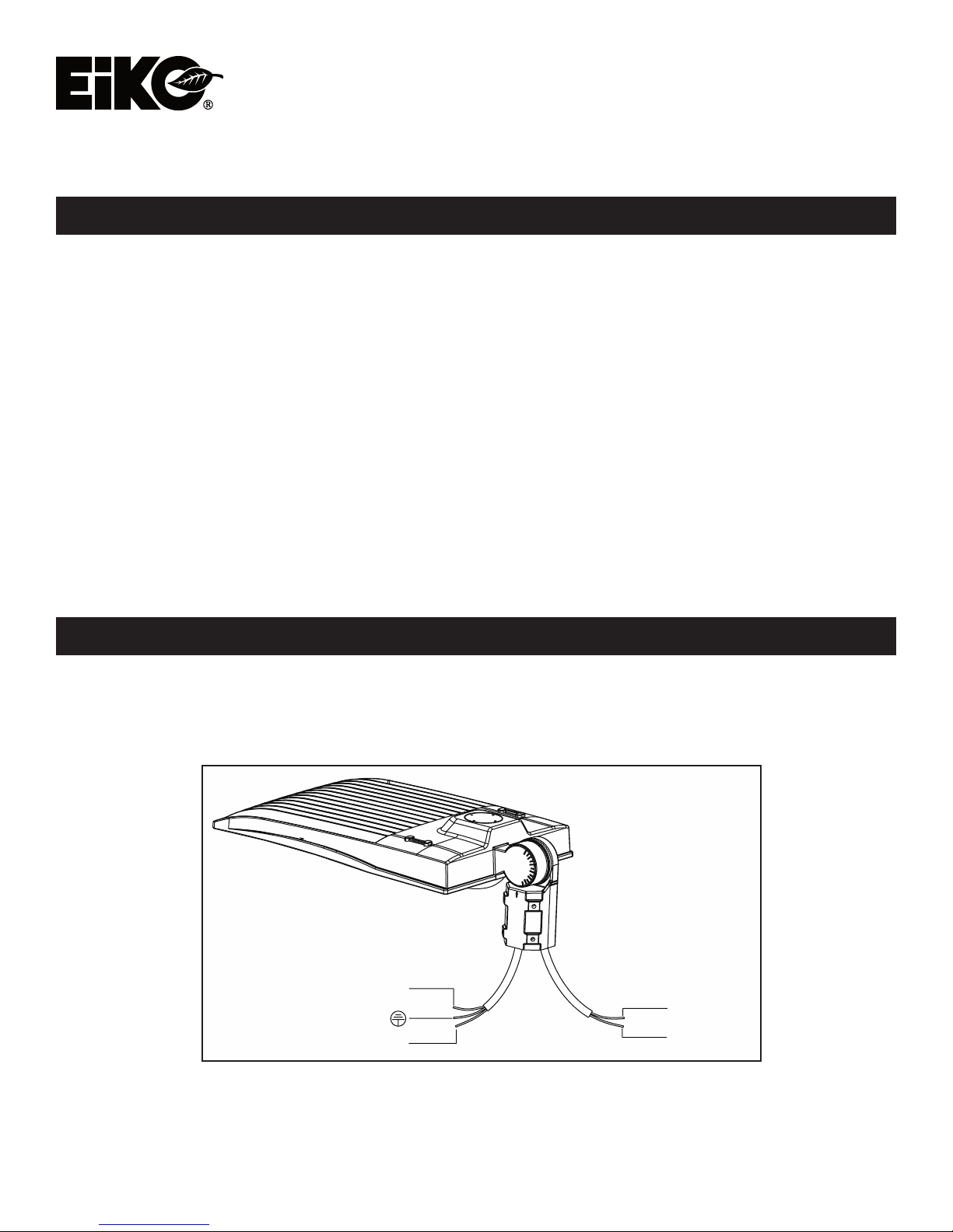
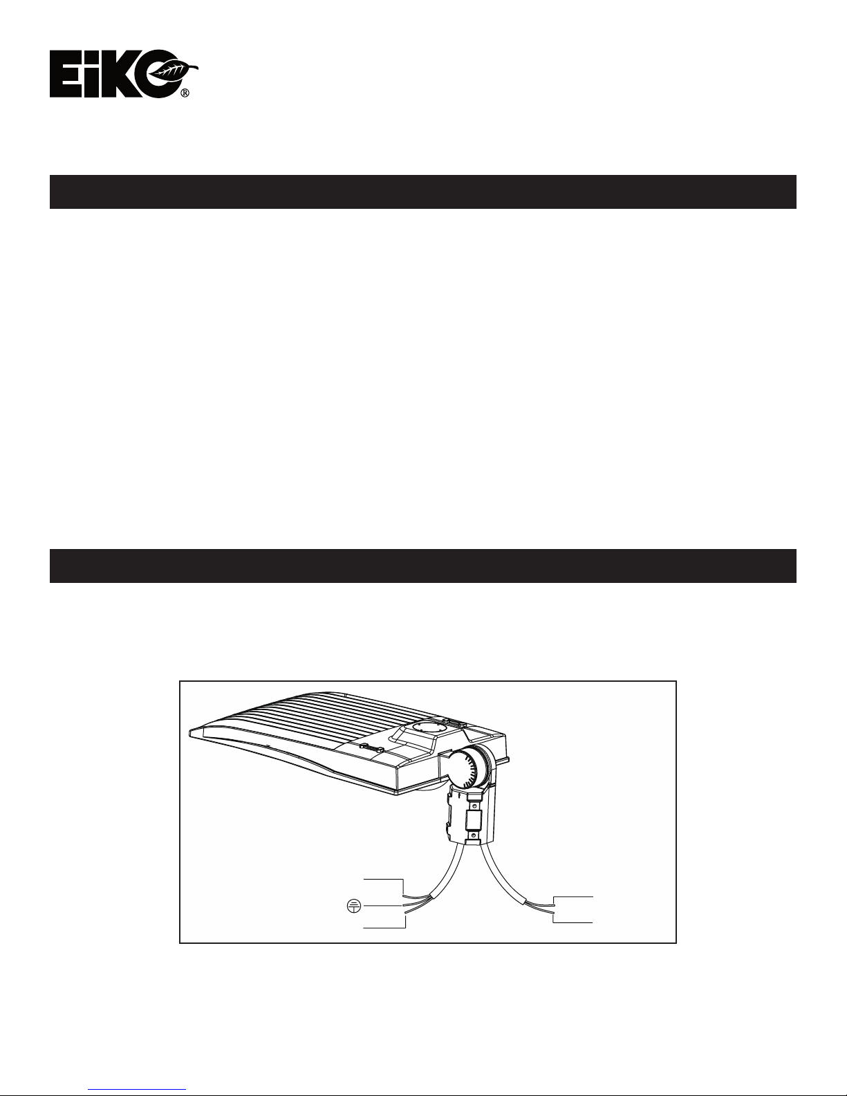
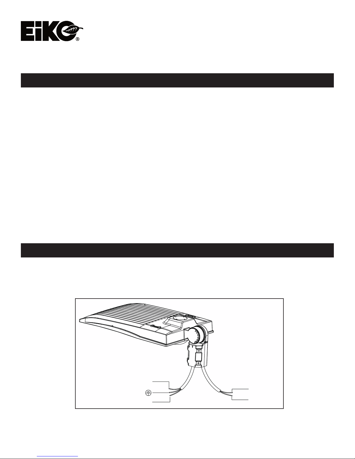
WIRING DIAGRAM:
3 DIFFERENT DIMMING FUNCTIONS ARE AVAILABLE IN THIS LIGHT FIXTURE:
1. Constant current can be achieved by 1-10V DC dimming.
2. PWM signal dimming.
3. Variation of resistance unit dimming.
Black/Brown: ACL
Green/Yellow: Ground
White/Blue: ACN
Dim+
Dim-
EiKO Global, LLC • 23220 W. 84th St, Shawnee, KS 66227 • (P) 1-800-852-2217 • (F) 1-800-492-8975 • eiko.com
EiKO Canada • 81 King St, Barrie, Ontario L4N 6B5 • (P) 1-705-721-5189 • (F) 1-705-721-7855 • [email protected]
Page 2
INSTALLATION:
ALWAYS TURN OFF THE POWER SUPPLY FROM MAIN CIRCUIT BREAKER FIRST!
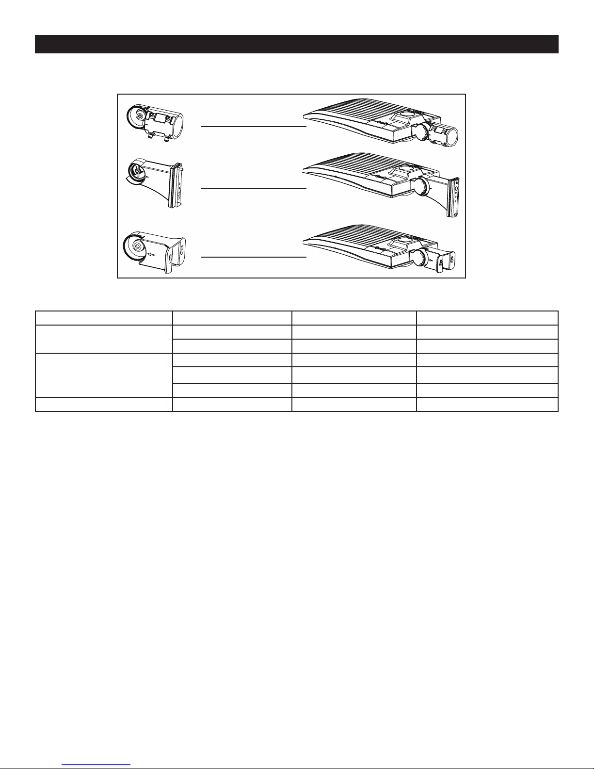
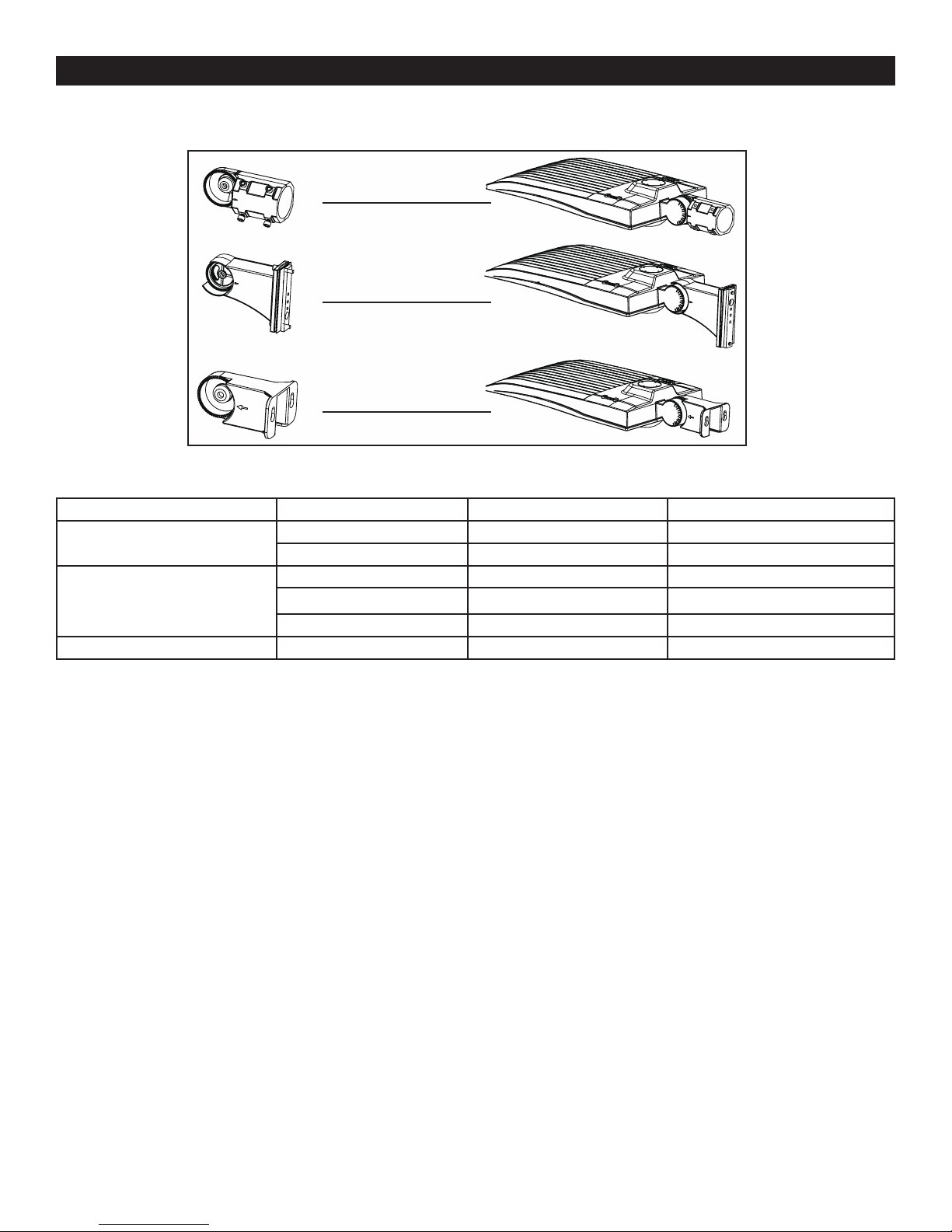
MOUNTING BRACKET OPTIONS
Slip Fitter
Direct Mount
Yoke Mount
BOLT TORQUE SPEC
TABLE 1 Bolts Nm Ft-lbs
Slip Fitter
Direct Mount
Yoke Mount M10 14.7 Nm 10.8 Ft-lbs
M8 7.8 Nm 5.8 Ft-lbs
M10 14.7 Nm 10.8 Ft-lbs
M4 1 Nm 0.7 Ft-lbs
M8 7.8 Nm 5.8 Ft-lbs
M10 14.7 Nm 10.8 Ft-lbs
EiKO Global, LLC • 23220 W. 84th St, Shawnee, KS 66227 • (P) 1-800-852-2217 • (F) 1-800-492-8975 • eiko.com
EiKO Canada • 81 King St, Barrie, Ontario L4N 6B5 • (P) 1-705-721-5189 • (F) 1-705-721-7855 • [email protected]
Page 3
INSTALLATION (continued):
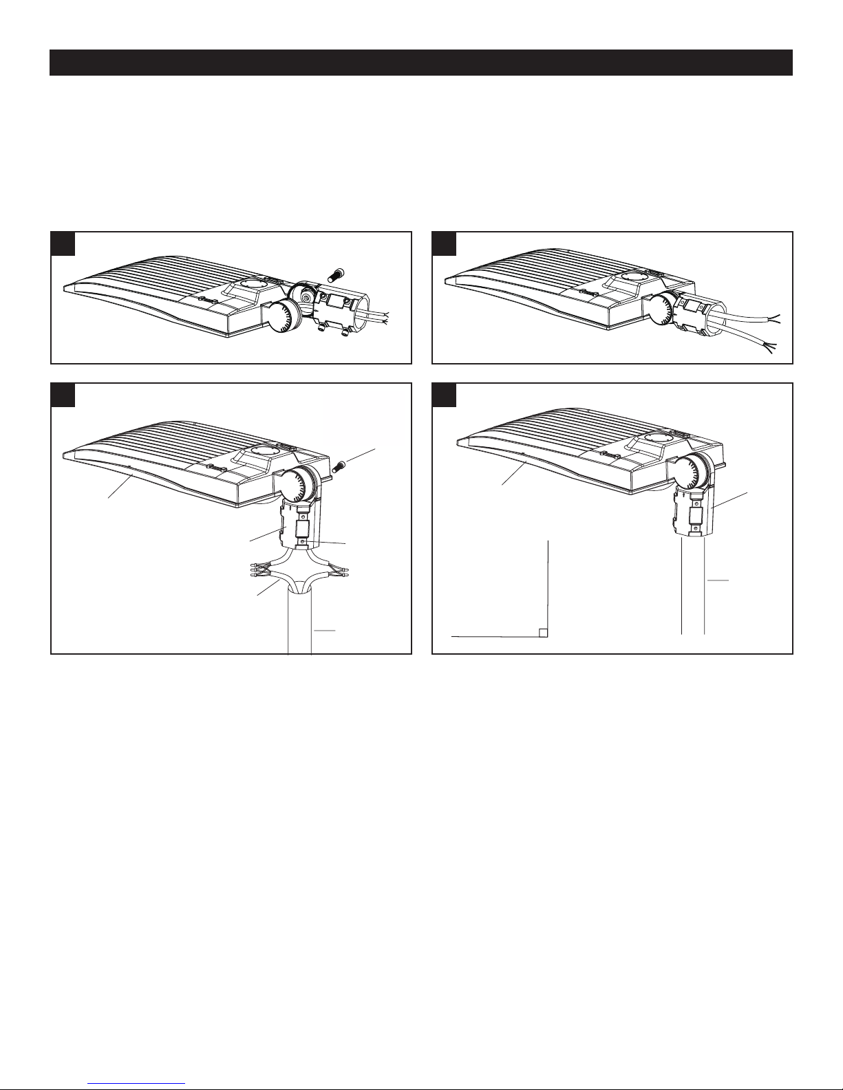
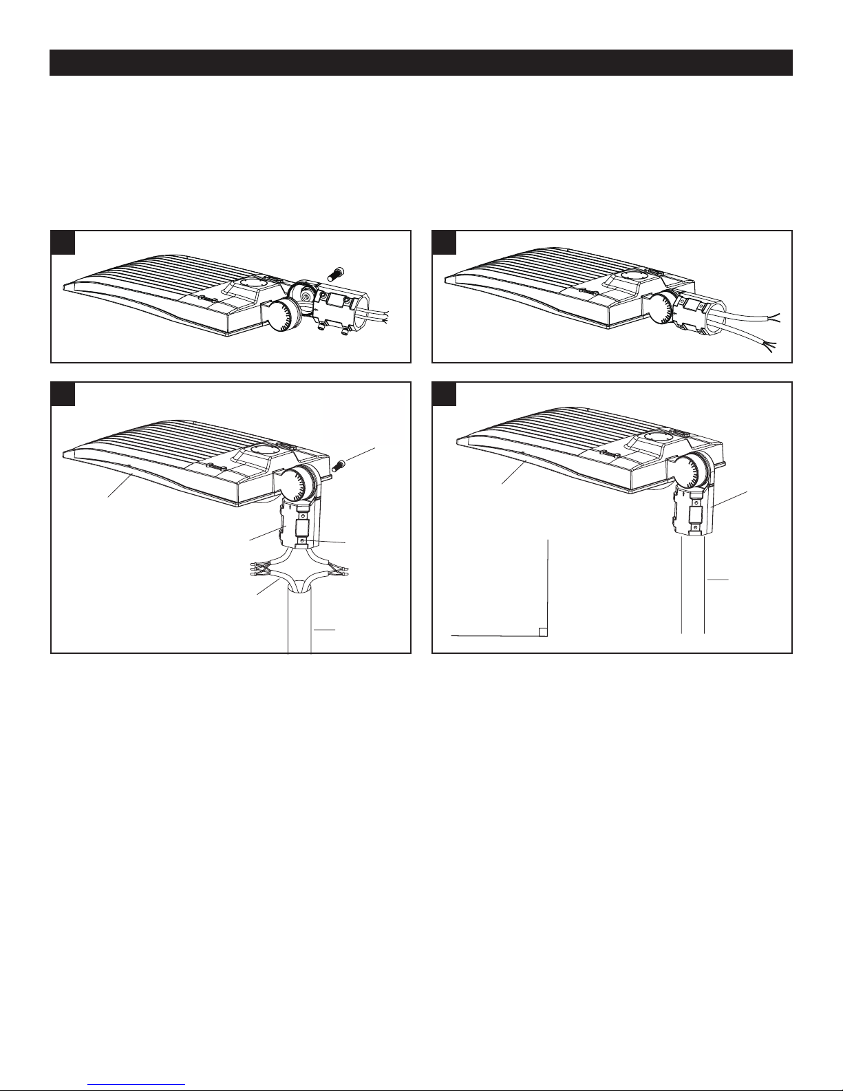
SLIP FITTER INSTALLATION
Please refer to Table 1 for torque spec on all bolts/screws.
Note: Adjustable angle is 0-90º
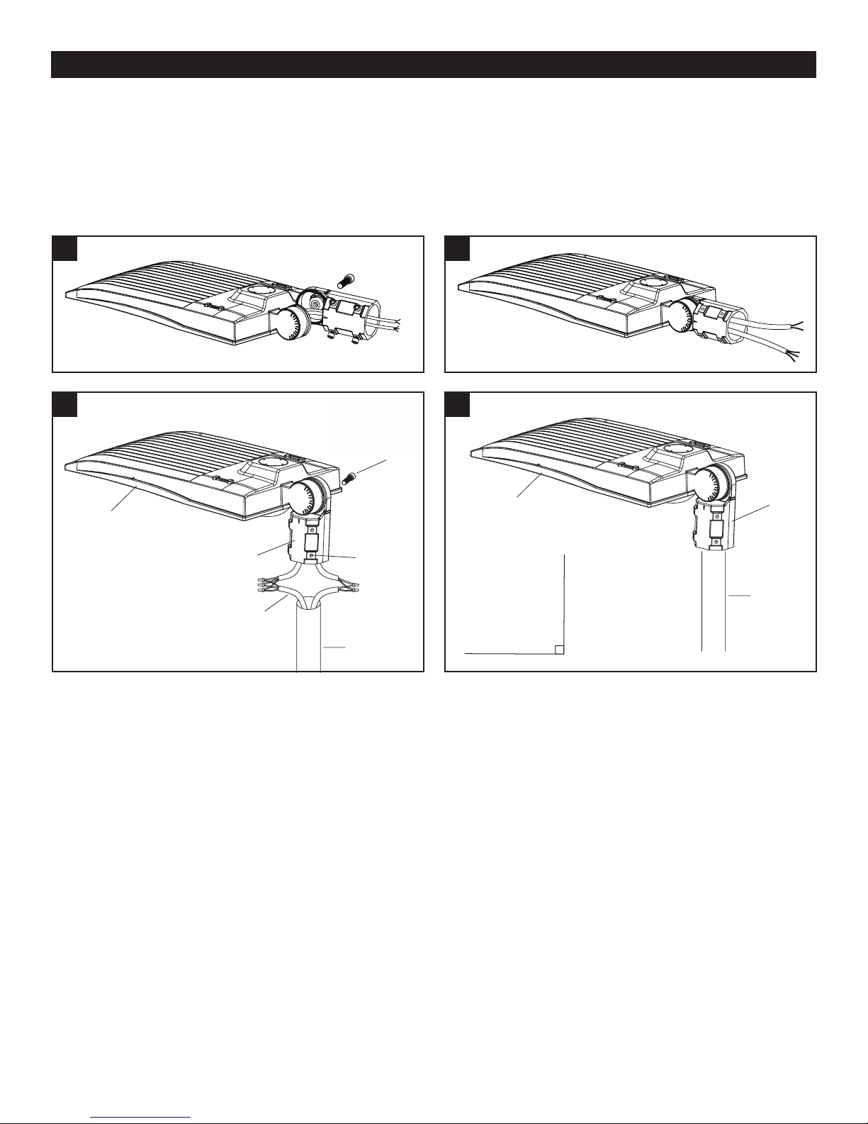
1. Remove the bracket mounting screws on the xture and run the wires through the bracket. (Fig. 1)
2. Install the bracket on the xture and tighten the bolt to spec. (Fig. 2)
3. Loosen the bolts on the bracket, connect the wires correctly, and pull the wires into the pole. (Fig. 3)
4. Place the bracket over the pole and tighten the bolts to spec (Fig. 4)
1
3
Fixture
Slip Fitter
Wires
Adjusting
Bolt
Locking
Bolt
Pole
2
4
Fixture
Slip
Fitter
Pole
Adjustable
0-90º
EiKO Global, LLC • 23220 W. 84th St, Shawnee, KS 66227 • (P) 1-800-852-2217 • (F) 1-800-492-8975 • eiko.com
EiKO Canada • 81 King St, Barrie, Ontario L4N 6B5 • (P) 1-705-721-5189 • (F) 1-705-721-7855 • [email protected]
Page 4
INSTALLATION (continued):
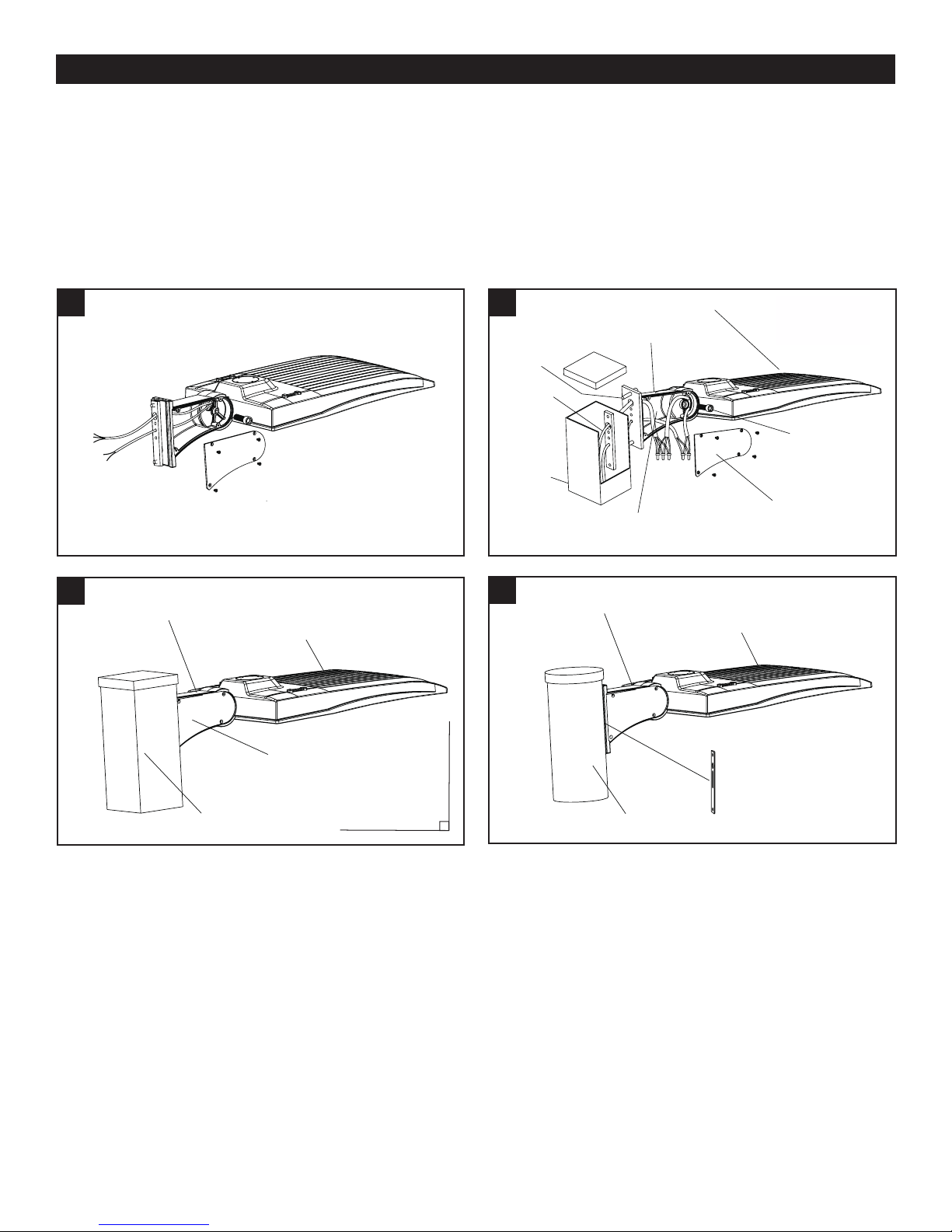
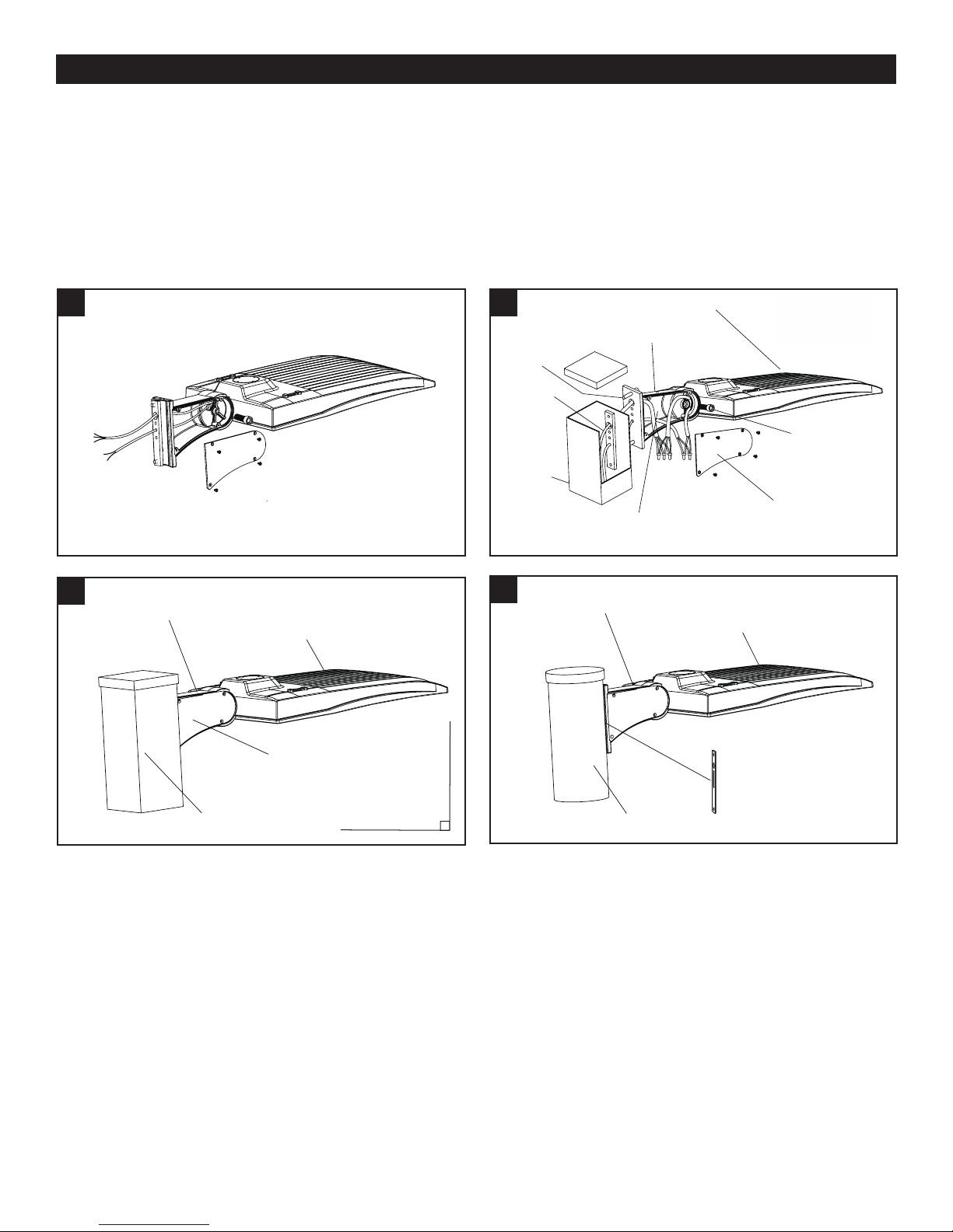
DIRECT MOUNT INSTALLATION
Please refer to Table 1 for torque spec on all bolts/screws.
Note: Adjustable angle is 0-90°
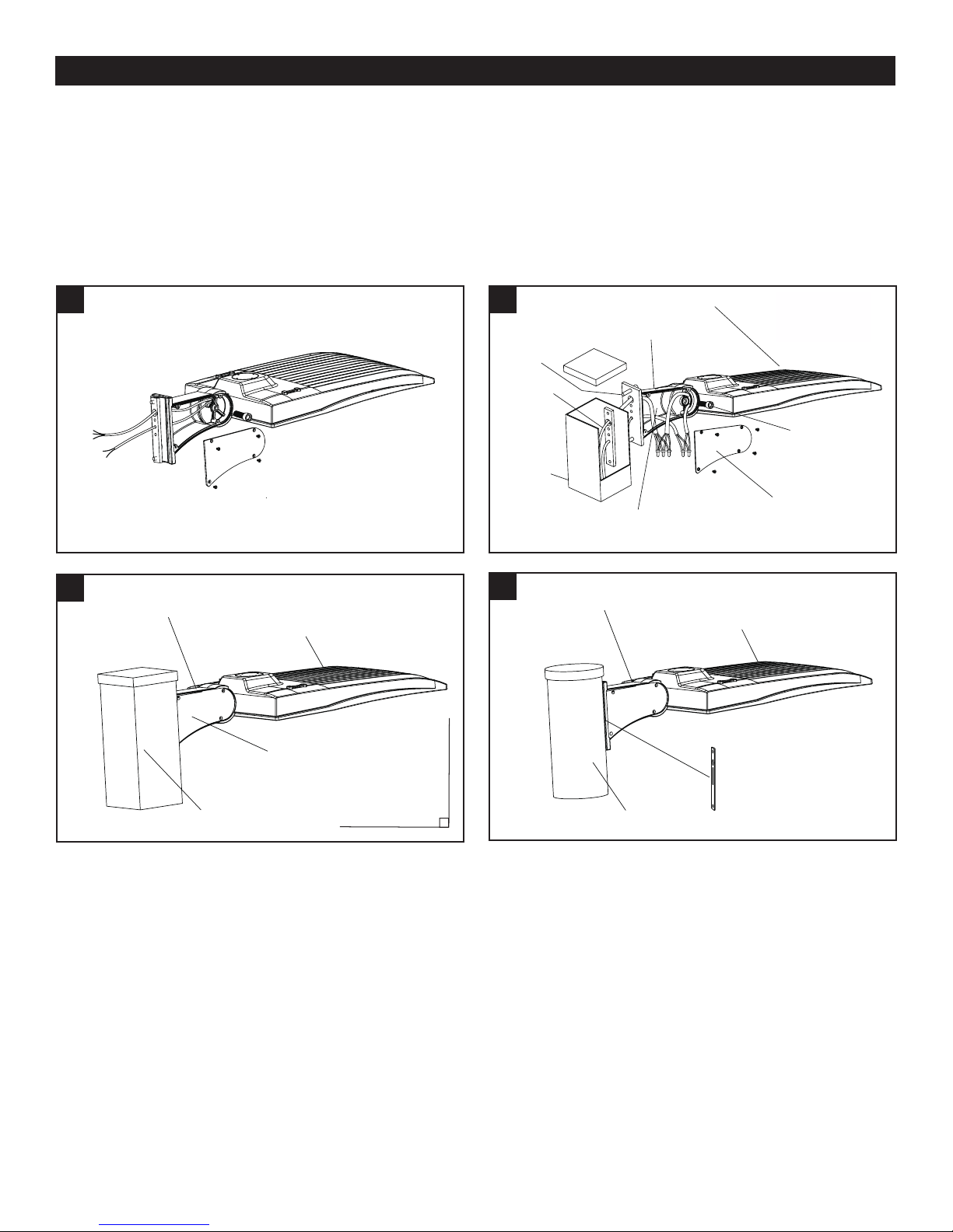
1. Remove the bracket mounting screws on the xture, open the side lid of the bracket. (Fig. 5)
2. Attach the direct mount bracket to square pole with bolts and tighten to spec, pull wire through bracket and into
the junction box, then connect the wires. (Fig. 6) If installing to a round pole, please remember to remove the
silicone plate. (Fig. 8)
3. Attach xture to the mounting bracket, tightening bolts to spec and secure side lid. (Fig. 7)
5
7
Direct Mount
Bracket
Fixture
6
Bolt
Cable
Square
Pole
8
Direct Mount
Bracket
Pole
Junction
Box
Direct Mount
Bracket
Fixture
Adjusting
Screws
Side Lid
Fixture
Side Lid
Silicone Plate
Square Pole
Adjustable
0-90º
Round Pole
EiKO Global, LLC • 23220 W. 84th St, Shawnee, KS 66227 • (P) 1-800-852-2217 • (F) 1-800-492-8975 • eiko.com
EiKO Canada • 81 King St, Barrie, Ontario L4N 6B5 • (P) 1-705-721-5189 • (F) 1-705-721-7855 • [email protected]
Page 5

INSTALLATION (continued):
YOKE MOUNT INSTALLATION
Please refer to Table 1 for torque spec on all bolts/screws.
Note: Adjustable angle is 0-90°
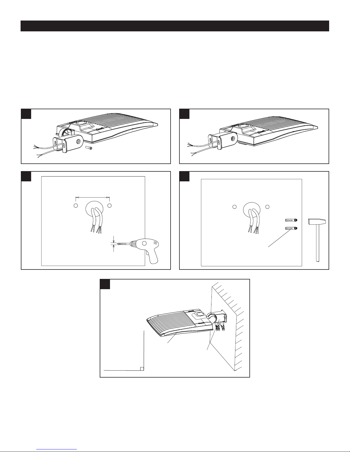
1. Remove the bracket mounting screws on the xture and run the wires through the bracket. (Fig. 9)
2. Install the bracket on the xture. (Fig. 10)
3. Drill holes on the mounting surface as shown. (Fig. 11)
4. Secure expansion bolts into the wall. (Fig.12)
5. Connect the xture to the bracket and tighten the bolts to spec; connect the wires properly and put them into the
junction box. (Fig. 13)
9
11
77mm
(3”)
10mm
(0.391”)
(25/64”)
10
12
Expansion Bolt
(included)
13
Adjustable
EiKO Global, LLC • 23220 W. 84th St, Shawnee, KS 66227 • (P) 1-800-852-2217 • (F) 1-800-492-8975 • eiko.com
EiKO Canada • 81 King St, Barrie, Ontario L4N 6B5 • (P) 1-705-721-5189 • (F) 1-705-721-7855 • [email protected]
Rev. 6/5/2018
0-90º
Fixture
Yoke Mount
Bracket
Page 6
INSTRUCCIONES DE INSTALACIÓN
VERT: PLATAFORMA DE ILUMINACIÓN DEL SITIO
VRT1 | VRT2
PRECAUCIÓN DE SEGURIDAD:
IMPORTANTE: LEA LAS INSTALACIONES CUIDADOSAMENTE ANTES DE INSTALAR. CONSERVE
ESTAS INSTRUCCIONES PARA REFERENCIA FUTURA.
• PRECAUCIÓN: NO USE EL GENERADOR ELÉCTRICO PARA PROBAR EL ARTEFACTO LED.
• PRECAUCIÓN: PARA EVITAR DESCARGAS ELÉCTRICAS Y DAÑOS, NO LA INSTALAR CUANDO LLORA.
• ADVERTENCIA: PARA EVITAR DESCARGAS ELÉCTRICAS O RIESGO DE INCENDIO, LA INSTALACIÓN
DEBE SER COMPLETADA POR EL OPERADOR CON CONOCIMIENTO ELÉCTRICO PROFESIONAL.
• ADVERTENCIA: POR FAVOR USE GUANTES PARA EVITAR LESIONES DURANTE LA INSTALACIÓN.
• ADVERTENCIA: DURANTE O DESPUÉS DE LA INSTALACIÓN, SI HAY SITUACIONES TALES COMO
HUMO O INCENDIO EN LOS ALAMBRES O ACCESORIOS, APAGUE LA POTENCIA INMEDIATAMENTE Y
PÓNGASE EN CONTACTO CON UN ELECTRICISTA CUALIFICADO.
• CONVENIENTE PARA USO AL AIRE LIBRE.
• MIN 75 ° C (167 ° F) CONDUCTOR DE SUMINISTRO.
• ESTE PRODUCTO DEBE SER INSTALADO DE ACUERDO CON EL CÓDIGO DE INSTALACIÓN
APLICABLE POR UNA PERSONA FAMILIARIZADA CON LA CONSTRUCCIÓN Y LA OPERACIÓN DEL
PRODUCTO Y LOS PELIGROS IMPLICADOS.
DIAGRAMA DE CABLEADO:
3 DIFERENTES FUNCIONES DE REGULACIÓN ESTÁN DISPONIBLES EN ESTE ACCESORIO DE LUZ:
1. La corriente constante puede lograrse con un atenuador de 1-10V CC.
2. Atenuación de señal PWM.
3. Variación de la atenuación de la unidad de resistencia.
Negro / Marrón: ACL
Verde / Amarillo: Tierra
Blanco / Azul: ACN
Dim+
Dim-
EiKO Global, LLC • 23220 W. 84th St, Shawnee, KS 66227 • (P) 1-800-852-2217 • (F) 1-800-492-8975 • eiko.com
EiKO Canada • 81 King St, Barrie, Ontario L4N 6B5 • (P) 1-705-721-5189 • (F) 1-705-721-7855 • [email protected]
Page 7

INSTALACIÓN:
¡SIEMPRE APAGUE PRIMERO LA FUENTE DE ALIMENTACIÓN DEL INTERRUPTOR DE CIRCUITO
PRINCIPAL!
OPCIONES DE SOPORTE DE MONTAJE
Slip Fitter
Montaje Directo
Montaje de Yugo
ESPECIFICACIÓN TORQUE DE PERNO
TABLA 1 Pernos Nm Ft-lbs
Slip Fitter
Montaje Directo
Montaje de Yugo M10 14.7 Nm 10.8 Ft-lbs
M8 7.8 Nm 5.8 Ft-lbs
M10 14.7 Nm 10.8 Ft-lbs
M4 1 Nm 0.7 Ft-lbs
M8 7.8 Nm 5.8 Ft-lbs
M10 14.7 Nm 10.8 Ft-lbs
EiKO Global, LLC • 23220 W. 84th St, Shawnee, KS 66227 • (P) 1-800-852-2217 • (F) 1-800-492-8975 • eiko.com
EiKO Canada • 81 King St, Barrie, Ontario L4N 6B5 • (P) 1-705-721-5189 • (F) 1-705-721-7855 • [email protected]
Page 8
INSTALACIÓN (continuación):
INSTALACIÓN DE DESLIZADOR
Consulte la tabla 1 para conocer las especificaciones de par en todos los pernos/tornillos.
Nota: el ángulo ajustable es 0-90º
1. Retire los tornillos de montaje del soporte en el dispositivo y pase los cables por el soporte. (Figura 1)
2. Instale el soporte en el accesorio y apriete el perno a la especicación. (Fig. 2)
3. Aoje los pernos en el soporte, conecte los cables correctamente y tire de los cables hacia el poste. (Fig. 3)
4. Coloque el soporte sobre el poste y apriete los pernos según las especicaciones (Fig. 4)
1
3
Accesorio
Slip Fitter
Alambres
Perno de
ajuste
Cierre
Tornillo
Polo
2
4
Accesorio
Ajustable
Slip
Fitter
Polo
0-90º
EiKO Global, LLC • 23220 W. 84th St, Shawnee, KS 66227 • (P) 1-800-852-2217 • (F) 1-800-492-8975 • eiko.com
EiKO Canada • 81 King St, Barrie, Ontario L4N 6B5 • (P) 1-705-721-5189 • (F) 1-705-721-7855 • [email protected]
Page 9
INSTALACIÓN (continuación):
INSTALACIÓN DE MONTAJE DIRECTO
Consulte la tabla 1 para conocer las especificaciones de par en todos los pernos/tornillos.
Nota: El ángulo ajustable es 0-90°
1. Retire los tornillos de montaje del soporte en el accesorio, abra la tapa lateral del soporte. (Fig. 5)
2. Fije el soporte de montaje directo al poste cuadrado con pernos y apriételo a la especicación, tire del cable a
través del soporte y dentro de la caja de conexiones, luego conecte los cables. (Fig. 6) Si se instala en un poste
redondo, recuerde retirar la placa de silicona. (Fig. 8)
3. Fije el accesorio al soporte de montaje y asegure la tapa lateral. (Fig. 7)
5
7
Soporte de
montaje directo
Accesorio
6
Tornillo
Cable de
poste
Polo
cuadrado
8
Soporte de
montaje directo
Unión
Caja
Soporte de
montaje directo
Accesorio
Tornillos
de ajuste
Tapa lateral
Accesorio
Tapa lateral
Placa de silicona
Polo cuadrado
Ajustable
0-90º
Polo Redondo
EiKO Global, LLC • 23220 W. 84th St, Shawnee, KS 66227 • (P) 1-800-852-2217 • (F) 1-800-492-8975 • eiko.com
EiKO Canada • 81 King St, Barrie, Ontario L4N 6B5 • (P) 1-705-721-5189 • (F) 1-705-721-7855 • [email protected]
Page 10
INSTALACIÓN (continuación):
MONTAJE DEL YUGO
Consulte la tabla 1 para conocer las especificaciones de par en todos los pernos/tornillos.
Nota: El ángulo ajustable es 0-90°
1. Retire los tornillos de montaje del soporte en el dispositivo y pase los cables por el soporte. (Fig. 9)
2. Instale el soporte en el accesorio. (Fig. 10)
3. Taladre oricios en la supercie de montaje como se muestra. (Fig. 11)
4. Asegure los pernos de expansión en la pared. (Fig.12)
5. Conecte el accesorio al soporte y apriete los tornillos; Conecte los cables correctamente y colóquelos en la caja
de conexiones. (Fig. 13)
9
11
77mm
(3”)
10mm
(0.391”)
(25/64”)
10
12
Perno de
expansión
(incluido)
13
Adjustable
EiKO Global, LLC • 23220 W. 84th St, Shawnee, KS 66227 • (P) 1-800-852-2217 • (F) 1-800-492-8975 • eiko.com
EiKO Canada • 81 King St, Barrie, Ontario L4N 6B5 • (P) 1-705-721-5189 • (F) 1-705-721-7855 • [email protected]
Rev. 6/5/2018
0-90º
Accesorio
Soporte de
montaje del
yugo
Page 11
INSTRUCTIONS D’INSTALLATION
VERT: PLATEFORME D’ÉCLAIRAGE DE SITE
VRT1 | VRT2
MESURE DE SÉCURITÉ:
IMPORTANT: LISEZ ATTENTIVEMENT LES INSTRUCTIONS AVANT D’INSTALLER. CONSERVEZ CES
INSTRUCTIONS POUR RÉFÉRENCE FUTURE.
• ATTENTION: N’UTILISEZ PAS DE GÉNÉRATEUR ÉLECTRIQUE POUR TESTER L’APPAREIL.
• ATTENTION: POUR ÉVITER LES CHOCS ÉLECTRIQUES ET LES DOMMAGES, NE PAS INSTALLER LORS
DE LA PLUIE.
• AVERTISSEMENT: POUR ÉVITER LES CHOCS ÉLECTRIQUES OU LES RISQUES D’INCENDIE,
L’INSTALLATION DOIT ÊTRE COMPLÉTÉE PAR L’OPÉRATEUR AVEC DES CONNAISSANCES
ÉLECTRIQUES PROFESSIONNELLES.
• AVERTISSEMENT: VEUILLEZ PORTER DES GANTS POUR ÉVITER LES BLESSURES PENDANT
L’INSTALLATION.
• AVERTISSEMENT: PENDANT OU APRÈS L’INSTALLATION, SI IL Y A DES SITUATIONS TELLES QU’UNE
FUMÉE OU UN INCENDIE DANS LES FILS OU LES FIXTURES, VEUILLEZ COUPER L’ALIMENTATION
IMMÉDIATEMENT ET CONTACTER UN ÉLECTRICIEN QUALIFIÉ.
• ADAPTÉ POUR L’UTILISATION EXTÉRIEURE.
• CONDUCTEUR D ‘ALIMENTATION MIN 75 ° C (167 ° F).
• CE PRODUIT DOIT ÊTRE INSTALLÉ CONFORMÉMENT AU CODE D’INSTALLATION APPLICABLE PAR
UNE PERSONNE FAMILIALE AVEC LA CONSTRUCTION ET L’EXPLOITATION DU PRODUIT ET LES
DANGERS IMPLIQUÉS.
WIRING DIAGRAM:
3 FONCTIONS DE GRADATION DIFFÉRENTES SONT DISPONIBLES DANS CE LUMINAIRE:
1. Un courant constant peut être atteint par une gradation de 1 à 10 V CC.
2. Gradation du signal PWM.
3. Variation de la gradation de l’unité de résistance.
Noir / Marron: ACL
Vert / Jaune: Terre
Blanc / Bleu: ACN
Dim+
Dim-
EiKO Global, LLC • 23220 W. 84th St, Shawnee, KS 66227 • (P) 1-800-852-2217 • (F) 1-800-492-8975 • eiko.com
EiKO Canada • 81 King St, Barrie, Ontario L4N 6B5 • (P) 1-705-721-5189 • (F) 1-705-721-7855 • [email protected]
Page 12
INSTALLATION:
TOUJOURS COUPER L’ALIMENTATION DU DISJONCTEUR PRINCIPAL EN PREMIER!
OPTIONS DE SUPPORT DE MONTAGE
Slip Fitter
Montage Direct
Montage de
l’étrier
BOULON TORQUE SPEC
TABLEAU 1 Boulons Nm Ft-lbs
Slip Fitter
Montage Direct
Montage de l’étrier M10 14.7 Nm 10.8 Ft-lbs
M8 7.8 Nm 5.8 Ft-lbs
M10 14.7 Nm 10.8 Ft-lbs
M4 1 Nm 0.7 Ft-lbs
M8 7.8 Nm 5.8 Ft-lbs
M10 14.7 Nm 10.8 Ft-lbs
EiKO Global, LLC • 23220 W. 84th St, Shawnee, KS 66227 • (P) 1-800-852-2217 • (F) 1-800-492-8975 • eiko.com
EiKO Canada • 81 King St, Barrie, Ontario L4N 6B5 • (P) 1-705-721-5189 • (F) 1-705-721-7855 • [email protected]
Page 13
INSTALLATION (suite):
INSTALLATION DE GLISSEUR
Veuillez vous référer au Tableau 1 pour la spécification de couple sur tous les boulons/vis.
Note: L’angle réglable est 0-90º
1. Retirez les vis de xation du support sur le luminaire et faites passer les ls dans le support. (Fig. 1)
2. Installez le support sur le luminaire et serrez le boulon selon les spécications. (Fig. 2)
3. Desserrez les boulons sur le support, connectez les ls correctement, et tirez les ls dans le poteau. (Fig. 3)
4. Placez le support sur le poteau et serrez les boulons selon les spécications (Fig. 4)
1
3
Fixation
Slip Fitter
Fils
Ajustement
du boulon
Verrouillage
Boulon
Pôle
2
4
Fixation
Slip
Fitter
Pôle
Réglable
0-90º
EiKO Global, LLC • 23220 W. 84th St, Shawnee, KS 66227 • (P) 1-800-852-2217 • (F) 1-800-492-8975 • eiko.com
EiKO Canada • 81 King St, Barrie, Ontario L4N 6B5 • (P) 1-705-721-5189 • (F) 1-705-721-7855 • [email protected]
Page 14
INSTALLATION (suite):
INSTALLATION EN MONTAGE DIRECT
Veuillez vous référer au Tableau 1 pour la spécification de couple sur tous les boulons/vis.
Note: L’angle réglable est 0-90°
1. Retirez les vis de xation du support sur le luminaire, ouvrez le couvercle latéral du support. (Fig. 5)
2. Fixez le support de montage direct au poteau carré à l’aide de boulons et serrez-le selon les spécications, tirez le
l à travers le support et dans la boîte de jonction, puis connectez les ls. (Fig. 6) Si vous installez sur un poteau
rond, n’oubliez pas d’enlever la plaque de silicone. (Fig. 8)
3. Fixez le luminaire au support de montage et xez le couvercle latéral. (Fig. 7)
5
7
Support de
montage direct
Couvercle
latéral
Poteau carré
Fixation
Réglable
0-90º
6
Boulon
Câble
poteau
Poteau
carré
8
de
Support de
montage direct
Support de
montage
direct
Jonction
Boîte
Pôle rond
Fixation
Vis de
réglage
Couvercle
latéral
Fixation
Plaque de silicone
EiKO Global, LLC • 23220 W. 84th St, Shawnee, KS 66227 • (P) 1-800-852-2217 • (F) 1-800-492-8975 • eiko.com
EiKO Canada • 81 King St, Barrie, Ontario L4N 6B5 • (P) 1-705-721-5189 • (F) 1-705-721-7855 • [email protected]
Page 15
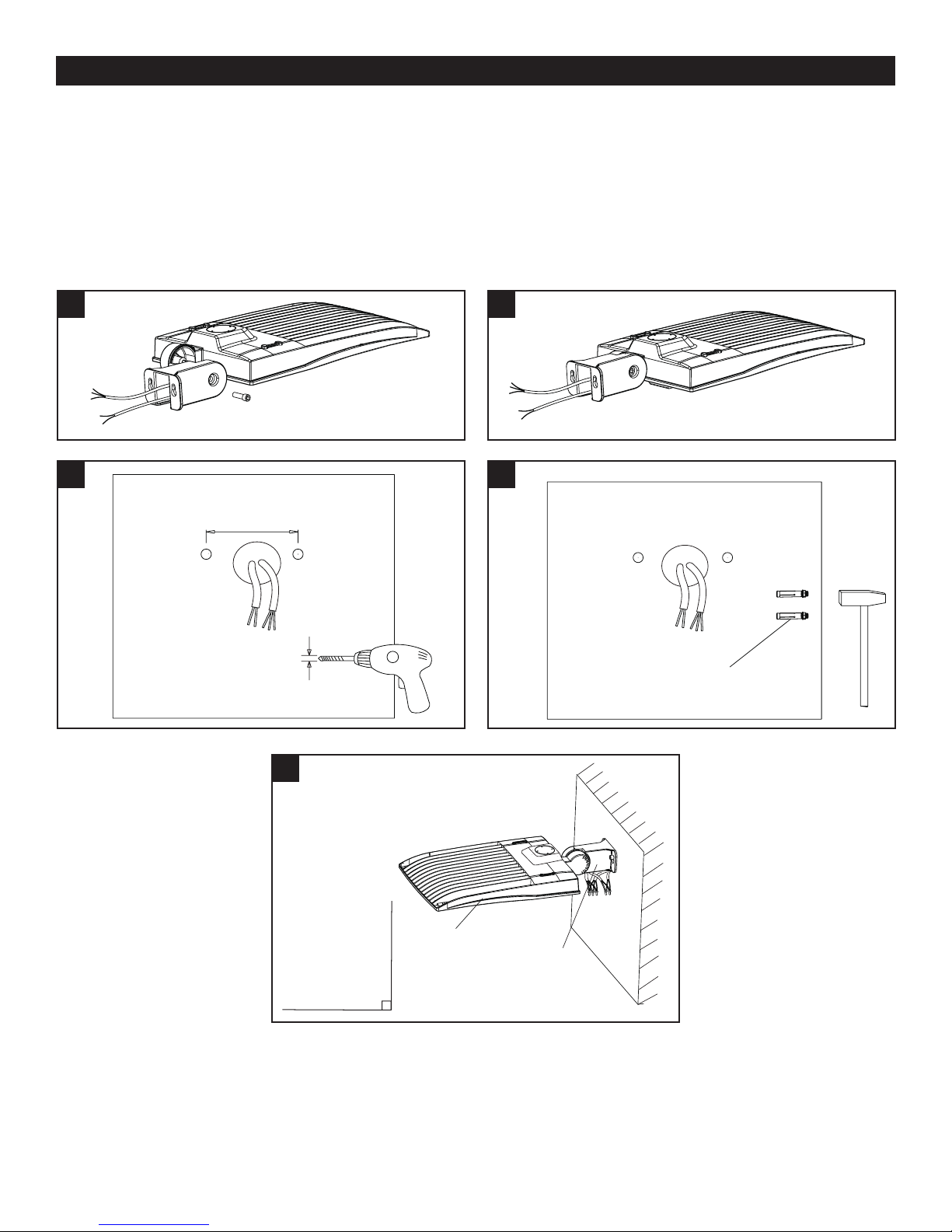
INSTALLATION (suite):
INSTALLATION DE L’ÉTRIER
Veuillez vous référer au Tableau 1 pour la spécification de couple sur tous les boulons/vis.
Note: L’angle réglable est 0-90°
1. Retirez les vis de xation du support sur le luminaire et faites passer les ls dans le support. (Fig. 9)
2. Installez le support sur l’appareil. (Fig. 10)
3. Percez des trous sur la surface de montage comme indiqué. (Fig. 11)
4. Fixez les boulons d’expansion dans le mur. (Fig.12)
5. Connectez le luminaire au support et serrez les vis; connectez les ls correctement et placez-les dans la boîte de
jonction. (Fig. 13)
9
11
77mm
(3”)
10mm
(0.391”)
(25/64”)
10
12
Boulon
d’expansion
(inclus)
13
Réglable
EiKO Global, LLC • 23220 W. 84th St, Shawnee, KS 66227 • (P) 1-800-852-2217 • (F) 1-800-492-8975 • eiko.com
EiKO Canada • 81 King St, Barrie, Ontario L4N 6B5 • (P) 1-705-721-5189 • (F) 1-705-721-7855 • [email protected]
Rev. 6/5/2018
0-90º
Fixation
Support de
montage de
l’étrier
 Loading...