

Eiko VOL22-3CP-XXK-U, VOL22-3C-XXK-U, VOL24-5CP-XXK-U, VOL24-5C-XXK-U Installation Instructions Manual
INSTALLATION INSTRUCTIONS
VOL22-3C-XXK-U | VOL22-3CP-XXK-U
VOL24-5C-XXK-U | VOL24-5CP-XXK-U
SAFETY PRECAUTION:
To reduce the risk of death, personal injury or property damage from re, electric shock, falling parts, cuts/abrasions, and
other hazards read all warnings and instructions included with and on the xture box and all xture labels.
Before installing, servicing, or performing routine maintenance upon this equipment, follow these general precautions.
Commercial installation, service and maintenance of luminaires should be performed by a qualied licensed electrician.
For the installation: If you are unsure about the installation or maintenance of the luminaires, consult a qualied licensed
electrician and check your local electrical code.
To prevent wiring damage or abrasion, do not expose wiring to edges of sheet metal or other sharp objects.
Do not make or alter any open holes in an enclosure of wiring or electrical components during kit installation.
WARNING: RISK OF FIRE OR ELECTRICAL SHOCK
Turn off electrical power at fuse or circuit breaker box before wiring xture to the power supply.
Turn off the power when you perform any maintenance.
Verify that supply voltage is correct by comparing it with the luminaire label information.
All wiring connections should be capped with UL approved wire connectors.
CAUTION: RISK OF INJURY
Avoid direct eye exposure to the light source while it is on.
Account for small parts and destroy packing material, as these may be hazardous to children.
Risk of burns. Disconnect power and allow xture to cool before changing bulb or handling xture.
GREEN GROUND SCREW PROVIDED IN PROPER LOCATION. DO NOT RELOCATE.
MINIMUM 90˚C SUPPLY CONDUCTORS.
SPECIFICATIONS AND DIMENSIONS ARE SUBJECT TO CHANGE WITHOUT NOTICE.
SUITABLE FOR DRY OR DAMP LOCATION, TYPE IC.
INSTALLATION:
ALWAYS TURN OFF THE POWER SUPPLY FROM MAIN CIRCUIT BREAKER FIRST!
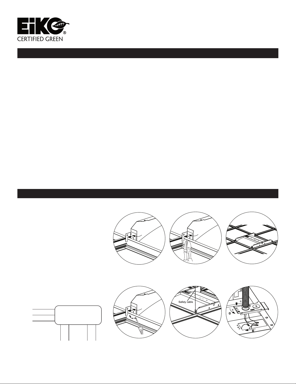
1. Bend out mounting tab 90 degrees on
each corner.
2. Use side cutters to adjust each tab to
height of T-grid.
3. Lay xture into T-grid.
4. Bend tabs ush against T-grid in order
to clear corner for ceiling tile.
5. Use a #8×1/4” sheet metal screw
to fasten xture to T-grid and use a
hanger wire to tie off appropriately in
accordance with local building codes
(screws and hanger wires supplied by
others).
6. Ensure that the wiring of the last xture
in the row is properly terminated.Then
make all electrical connections to the
xture. Attach the wiring access cover
plate.
WIRING DIAGRAM
Black (Line)
White (Neutral)
Green (Grd)
120-277v
Dimming Wire
to 0-10v IEC
compliant control
LED DRIVER
Grey (Dim-)
Purple (Dim+)
Blue (-)
Red (+)
Lead wire to
LED load
FIG. 1 FIG. 2 FIG. 3
FIG. 4 FIG. 5 FIG. 6
EiKO Global, LLC • 23220 W. 84th St, Shawnee, KS 66227 • (P) 1-800-852-2217 • (F) 1-800-492-8975 • eiko.com
EiKO Canada • 81 King St, Barrie, Ontario L4N 6B5 • (P) 1-705-721-5189 • (F) 1-705-721-7855 • orderdesk@eiko.com
SURFACE MOUNT INSTALLATION:
WARNING: Risk of Electric Shock. Disconnect power at fuse or circuit breaker before installing or servicing.
WARNING: Risk of Fire/Electric Shock. If not qualied, consult an electrician.
WARNING: Risk of re or electric shock. Luminaires wiring, ballasts, or other electrical parts may be damaged when
drilling for installation of reector kit hardware. Check for enclosed wiring and components.
NOTE: This product must be installed in accordance with the applicable installation code by a certied electrician,
familiar with the construction and operation of the product and hazards involved.
NOTE: Only those open holes indicated in the photographs and/or drawings may be made or altered as a result of kit
installation. Do not leave any other open holes in an enclosure of wiring or electrical components.
NOTE: To prevent wiring damage or abrasion, do not expose wiring to edges of sheet metal or any sharp objects.
NOTE: Disconnect all power before proceeding.
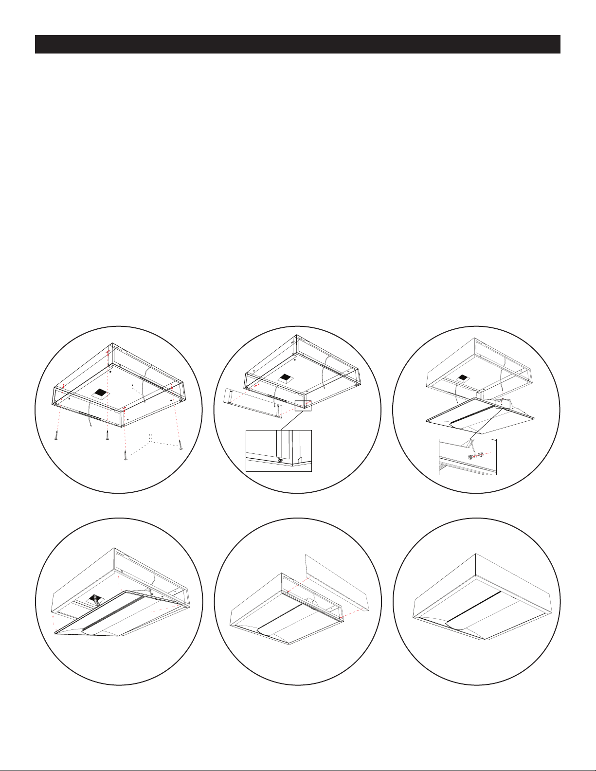
1. Using the appropriate dimensions and fasteners as shown in Fig. 1, rough junction box and loosely secure the surface
mount frame to the ceiling. Ensure the frame is square prior to fully securing the frame to the ceiling. Slots will allow
for adjustment once the frame is attached.
2. Secure end plate to one side of surface mout frame by securing clips to frame edge and rotating slots into studs on
frame. Secure using two #10-32 nuts.
3. Prior to wiring xture, secure safety cables at each end of the xture by attaching to the existing protruding screws
and secure with #10-32 nuts.
4. Make all electrical connections according to local code and make sure safety cables are secure. Angle the xture into
the bottom opening of the surface mount box. When installed properly, the xture will rest on the bottom ange of the
surface mount kit between locating tabs on all four corners. If the xture is not resting properly on the bottom ange,
lift it up and shift it until it rests into place.
5. Attach the nal end plate in the same manner as the rst end plate. Secure with two #10-32 nuts by lifting the edge of
the xture out of the way in order to thread onto the studs on the end plate.
6. Installation completed. Fixture is ready to power on.
Safety Cable
Safety Cable
J-Box
Secure end plate with
Guides for
securing kit
two #10-32 nuts
FIG. 1 FIG. 2 FIG. 3
Secure safety
cables at each
end of xture
with #10-32 nut
FIG. 4 FIG. 5 FIG. 6
EiKO Global, LLC • 23220 W. 84th St, Shawnee, KS 66227 • (P) 1-800-852-2217 • (F) 1-800-492-8975 • eiko.com
EiKO Canada • 81 King St, Barrie, Ontario L4N 6B5 • (P) 1-705-721-5189 • (F) 1-705-721-7855 • orderdesk@eiko.com
 Loading...