

Page 1
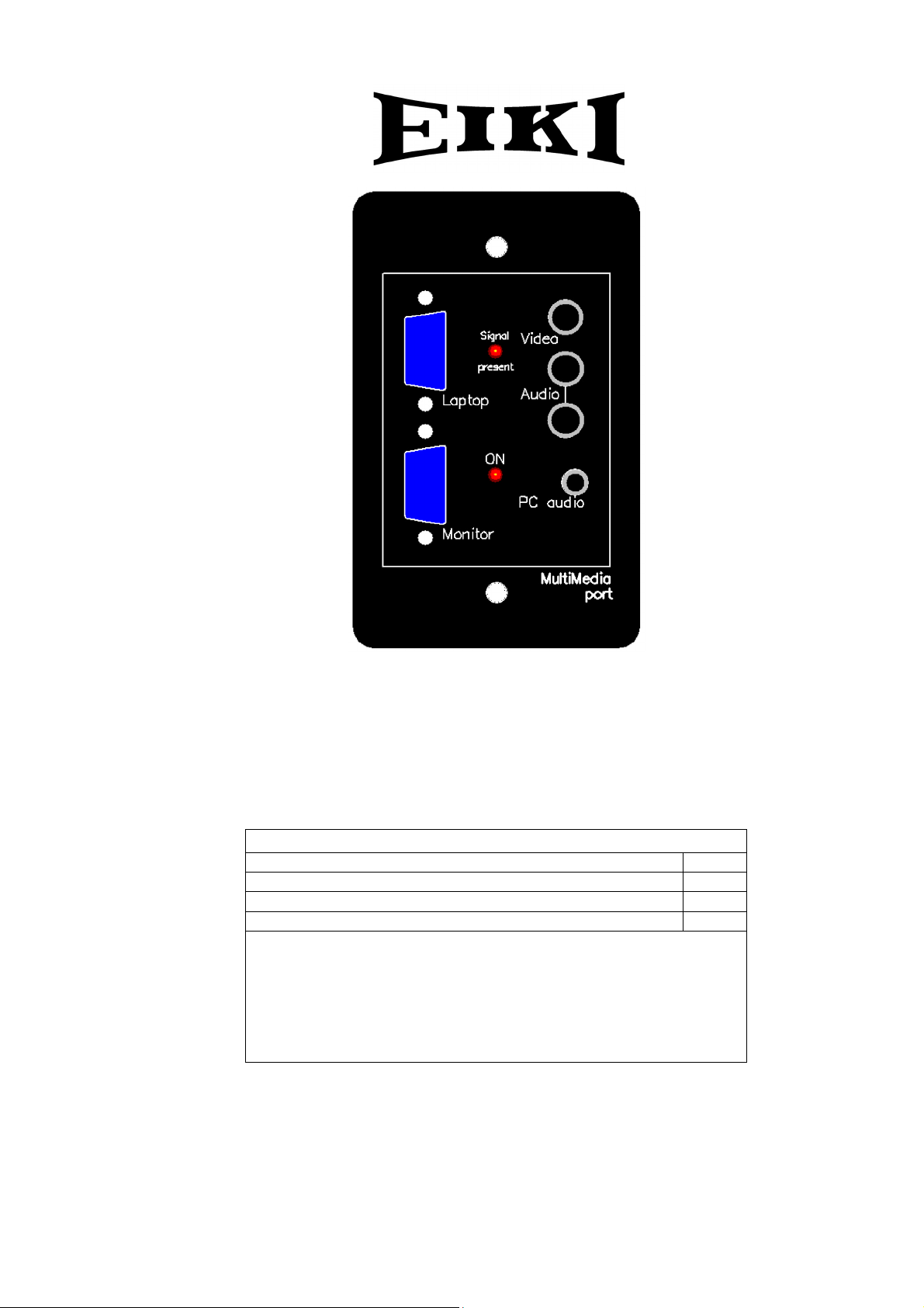
Multi Media Port
Instruction Manual
Eiki A-6
Package contents
Item Qty.
Multi Media Port 1
Interface cable 1
Screw terminal plugs 2
Please note:
Because its function can be shared with other equipment in a
system, a DC power supply is not included.
For standalone use, the power supply you use should be
capable of supplying 9 to 16 volts DC at up to 100mA.
Page 2
r
p
f
A
V:E1.03
To the System IntegratorR
Thank you for choosing Eiki A-6.
The Eiki A-6 Multi Media Port is ideal
for “smart classroom” projector
installations that combine fixed PC
and AV equipment with the ability to
plug in portable devices such as
laptops. The A-6 is a compact, easy
to install integrated wallplate and
VGA-AV switcher that is an ideal
companion to the MCS-1 Multi
Control System.
NOTE: This symbol and recycle system apply to EU
countries only and do not apply to countries in othe
areas of the world.
Please dispose of this equipment at your local
community waste collection/recycling centre. In the
European Union there are separate collection systems
for used electrical and electronic
Your EIKI product is designed
and manufactured with high
quality materials and
components which can be
recycled and reused.
This symbol means that
electrical and electronic
equipment, at their end-of-life,
should be disposed o
separately from your household
roducts.
For your safety
Please ensure that any wiring used to
connect an A-6 to other equipment is
kept clear of mains wiring and follows
applicable local wiring codes. Under no
circumstances may an A-6 be
connected directly to power mains
wiring.
Please ensure that the power supply
you are using meets your local safety
regulations and that its voltage does
not exceed 16 volts DC. Unregulated
power supplies can output voltages
that are well above what is shown on
their label.
EIKI A-6
Tested To Comply
With FCC Standards
FOR HOME OR OFFICE USE
Federal Communication Commission Notice
Note: This equipment has been tested and found to comply with the limits for a Class B digital device, pursuant to
part 15 of the FCC Rules. These limits are designed to provide reasonable protection against harmful interference in
a residential installation. This equipment generates, uses and can radiate radio frequency energy and, if not
installed and used in accordance with the instructions, may cause harmful interference to radio communications.
However, there is no guarantee that interference will not occur in a particular installation. If this equipment does
cause harmful interference to radio or television reception, which can be determined by turning the equipment off
and on, the user is encouraged to try to correct the interference by one or more of the following measures:
– Reorient or relocate the receiving antenna.
– Increase the separation between the equipment and receiver.
– Connect the equipment into an outlet on a circuit different from that to which the receiver is connected.
– Consult the dealer or an experienced radio/TV technician for help.
Do not make any changes or modifications to the equipment unless otherwise specified in the instructions. If such
changes or modifications should be made, you could be required to stop operation of the equipment.
Model Number : A-6
Trade Name : EIKI
Responsible party : EIKI International, Inc.
ddress : 30251 Esperanza Rancho Santa Margarita CA 92688-2132
Telephone No. : 800-242-3454 (949-457-0200)
Page 3
Introduction
The A-6 Multi Media Port combines the following
functions:
• Input plate
• Four input Audio-video switcher
• Two input RGBHV switcher
• RGBHV splitter
in a single-gang wallplate. The Eiki A-6 greatly
simplifies installation and cabling and avoids the
need in most cases for video/audio and RGBHV
switchers.
Anyone who has ever had to manage AV
facilities will appreciate these unique features of
the MultiMedia Port:
• A fast-response “Signal Present”
indicator LED for the laptop input helps a
user to quickly set up a laptop so that it
is outputting a signal.
• MultiMedia Ports can be installed in
different parts of a room and “daisychained” to create an economical multipoint input solution with minimal wiring
and no central switchers.
• A “Monitor” output allows a desktop PC
to display its output on a projector and
its own monitor at the same time.
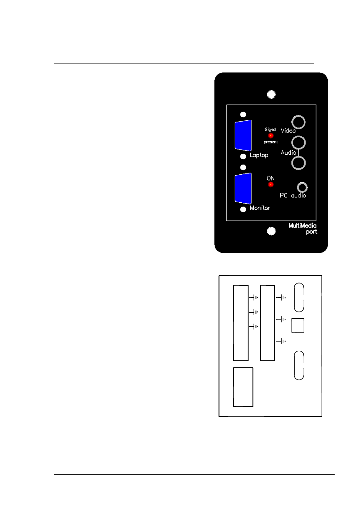
The diagrams on this page show the inputs and
outputs that are available on the A-6 Multi
Media Port. The rear connections use screw
terminal plugs to simplify the installation of
fixed wiring.
The Eiki A-6 is an ideal companion for the Eiki
MCS-1 and connects directly to it with the
supplied interface cable.
The A-6 may also be controlled by other
systems. It includes video sensor outputs that
may be read by external equipment. Or the A-6
may be used standalone and locked to any fixed
input arrangement by a combination of
connections on the interface cable.
Please note that the Cable Compensation
provision marked on the rear of the unit is not
implemented in current production.
Front view
V1in
V2in
V4in
Vout
RL1
RL2
+24v
& power
Control
A in 1
A in 2L
A in 2R
A in L
PC
A in R
A out L
A out R
Projector
PC
Long <--> Short
Cable Compensation
Rear view
Eiki A-6 manual Page 3
Page 4

(
)
r
(PC)
t
(laptop)
Input terminals
On the front of the unit there are the following connections:
• One VGA input
• One VGA monitor output. This follows the output of the switcher.
• Two RCA sockets for line audio, shared with a 3.5mm stereo jack
• One RCA socket for composite video input.
The audio and video inputs are accessed together as Input 3. The VGA input is
switched separately. If you want to use the audio inputs with the VGA input you
have to select them separately as AV input 3.
On the rear of the unit there are the following connections:
• One VGA input on HDDB15 connector
• One VGA projector output on HDDB15 connector
• Three audio inputs on screw terminal connectors. Input 1 is a mono input.
• Three video inputs on screw terminal connectors.
• One pair of stereo audio outputs on screw terminal connectors
• One Composite video output on screw terminal connectors
• Two breakout connections from the Control and Power socket for relay drive.
(See notes on the following page for more information.)
Audio input 4 would normally be used in conjunction with the rear PC input.
There is an internal 2 pin jumper that, when linked, converts to output to mono by
combining L and R audio signals.
With no control inputs asserted, AV 1 and the rear VGA input is selected.
Block diagram of the A-6 Multi Media port showing programming interface.
A out L
Connections
shown on a
light green
background
are on the rear
of the unit.
Those with a
grey
A in 1
A in 2 L
A in 2 R
Front L
Front R
PC audio
(L&R)
A in PC L
A in PC R
V1 in
V2 in
Video
V3 Front
V4 in
Rea
VGA in
Fron
L & R
Audio switcher
4 3 2 1
4 3 2 1
Video switcher
RGBHV
switcher
2 1
Audio
Buffer
Audio
Buffer
Video
Buffer
Sync
detect
RGBHV
Buffer
Sync
detect
background
are on the front.
Eiki A-6 manual Page 4
A out R
Vout
+24v
RL2
RL1
Control & Power
1. Relay drive 1
2. Relay drive 2
3.
4. RGB front/rear
5. AV swr LS bit
6. AV swr MS bit
7. RGBHV present
8. Video present
9. Gnd.
10. +9 to 24v DC
Rear
(Projector)
VGA out
Front
(Monitor)
Signal
Present
LED
Page 5

“
A typical application using an MCS-1 for control
Mains
Relay
RS-232
Video
RGBHV
External
relay
connections
Connect the
coil of a 12v
UR approved
DIN rail relay
to “RL1” and
+24v”.
The voltage
and current
limits are
determined by
the relay
used.
V1in
V2in
V4in
Vout
RL1
RL2
+24v
Control
& power
DVD-VCR
combo
A in 1
A in 2L
A in 2R
A in L
A in R
A out L
A out R
PC
PC
Projector
Rear
view
Desk
PC
External A/V
device, e.g.
Long <--> Short
Cable Compensation
camcorder
External PC,
e.g. laptop
Front
view
Audio
amplifier
RS232 ports
2-Aux.
1-Pgm.
DC In
MADE IN AUST RALIA
MultiMedia
Access
Port
9 - 12v
+ - centre
IR out
Port
1 - Gnd
2 - +12V
3 - Data
EIKI INDUSTRIAL CO., LTD
4 - IROut
5 - TxD 1
6 - RxD
4-12 BANZAI-CHO, KITA-KU
7 - TxD 2
OSAKA, 530-0028 JAPAN
8 - PIR in
RoHS
compliant
MCS-1
NANIWA BLDG.,
Eiki A-6 manual Page 5
Page 6

Programming an MCS-1 to control the A-6 Multi Media Port
• In the Eiki Control System Editor, select MCS-1 as your device.
• In “Edit behaviour” mode, double-click the key you wish to program. A
dialog like that shown will appear.
• You can choose the inputs of the A-6 you wish to select when the button is
pressed by using the drop-down items in the Multimedia Port section, as
shown.
• Eiki Control System Editor software version 2.7.15 or later has a “Relay
Output” drop-down item that allows you to operate an external relay which
can be used to control a motorised screen or lights, for example.
• Make sure that when you are programming keys that should not change the
state on the A-6 Multi Media Port, the selections are left at the default of
“No change”.
“AV 1 (rear)”
will select A in
1 and V1 in
inputs on the
rear of the unit.
Audio and video
inputs are
switched
simultaneously.
“RGB front” will
select the VGA
socket marked
“Laptop” on the
front of the unit.
Please note that
any audio
associated with an
RGB input must be
selected separately
using the
A/V Selection
drop-down. Audio
for RGB Front would
be selected with
“AV 3 (front)”
Eiki A-6 manual Page 6
Page 7

Interfacing to the MultiMedia Port.
If you wish to control the A-6 internal switchers in some other way, or configure the
unit as a standalone, fixed input wallplate, you will need to know the control port
connector pinouts for the ribbon cable. They are as follows:
Pin Function Type Comment
1 Relay output Logic Low RL1
2 Relay output Logic Low RL2 (not implemented on MCS-1)
3 GP output 2 Not used
4 RGBHV source Logic Low input Low = Front PC input
5 AV source 1 Logic Low input See table below
6 AV source 2 Logic Low input See table below
7 RGBHV sense Logic output
8 Video sense Logic output
9 GND
10 +24 v Power Any positive voltage from 9v to
30v. DC.
AV switcher truth table
Input Pin 5 Pin 6 Comments
AV in 1 (rear) H H Audio 1 is mono. Video 1. On rear
AV in 2 (rear) L H Audio and video 2 on rear
Video & Audio 3
(front)
A in PC (rear) L L Audio from rear PC socket
“H” = not connected.
“L” = connected to pin 9
H L Audio shared with front PC socket
Front video input
Video 4 input rear
Eiki A-6 manual Page 7
Page 8

U.S.A.
EIKI International, Inc.
30251 Esperanza
Rancho Santa Margarita
CA 92688-2132
U.S.A.
Tel : 800-242-3454 (949)-457-0200
Fax : 800-457-3454 (949)-457-7878
E-Mail : usa@eiki.com
Deutschland & Österreich
EIKI Deutschland GmbH
Am Frauwald 12
65510 Idstein
Deutschland
Tel : 06126-9371-0
Fax : 06126-9371-14
E-Mail : info@eiki.de
Eiki (Shanghai) Co., LTD
1. Dapu Road,
Golden Magnolia Plaza
#2109 Shanghai,
200023 China
Tel : 86-21-5396-0088
Fax : 86-21-5396-0318
E-mail : info@eikichina.com.cn
Canada
EIKI CANADA - Eiki International, Inc.
P.O. Box 156, 310 First St. - Unit 2,
Midland, ON, L4R 4K8, Canada
Tel : 800-563-3454 (705)-527-4084
Fax : 800-567-4069 (705)-527-4087
E-Mail : canada@eiki.com
Eastern Europe
EIKI CZECH spol. s.r.o.
Umělecká 15
170 00 Praha 7
Czech Republic
Tel : +42 02 20570024
+42 02 20571413
Fax : +42 02 20571411
E-Mail : easterneurope@eiki.de
Japan & Worldwide
EIKI Industrial Company Limited.
4-12 Banzai-Cho, Kita-Ku, Osaka,
530-0028 Japan
Tel : +81-6-6311-9479
Fax : +81-6-6311-8486
E-Mail : japan@eiki.com
For the latest software and information go to:
WorldWide Website http://www.eiki.com
 Loading...