

Page 1
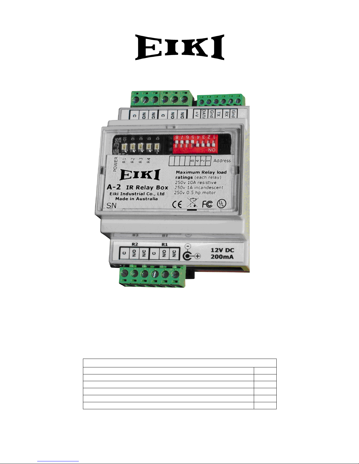
Eiki A-2
IR relay box
Instruction Manual
Package contents
Item Qty.
A-2 IR relay box 1
Screw terminal plugs for relay connection 4
Screw terminal plug for control connection 1
DC In plug 1
Manual 1
Page 2
To the System IntegratorR
Thank you for choosing Eiki A-2.
The A-2 IR Relay Box is part of the Eiki
control system family of products. It
is a simple, easy to set up and operate
IR or RS232 controllable 4 relay module
that allows for remote control operation
of many devices – projection screens,
lights, monitors etc or speaker
switching.
Before commencing installation, please
read these instructions carefully to get the
best results from your A-2.
Do not exceed maximum ratings.
For your safety
Please ensure that any wiring used to connect
A-2 to other equipment is kept clear of mains
wiring and follows applicable local wiring
codes. Mains wiring must only be carried
out by a qualified electrician.
Maximum switched load per relay
Resistive - 250 V, 10A
Motor - 250 V, 1/2 HP
Tungsten - 250 V, 1A
Make sure that the 12 volt power supply
you are using meets your local safety
regulations and that its voltage does not
exceed 16 volts DC. Unregulated power
supplies can output voltages that are well
above what is shown on their label.
NOTE: This symbol and recycle system apply to EU
countries only and do not apply to countries in othe
r
areas of the world.
Please dispose of this equipment at your local
community waste collection/recycling centre. In the
European Union there are separate collection systems
for used electrical and electronic
p
roducts.
Your EIKI product is designed
and manufactured with high
quality materials and
components which can be
recycled and reused.
This symbol means that
electrical and electronic
equipment, at their end-of-life,
should be disposed o
f
separately from your household
Federal Communication Commission Notice
Note: This equipment has been tested and found to comply with the limits for a Class B digital device, pursuant to
part 15 of the FCC Rules. These limits are designed to provide reasonable protection against harmful interference in
a residential installation. This equipment generates, uses and can radiate radio frequency energy and, if not
installed and used in accordance with the instructions, may cause harmful interference to radio communications.
However, there is no guarantee that interference will not occur in a particular installation. If this equipment does
cause harmful interference to radio or television reception, which can be determined by turning the equipment off
and on, the user is encouraged to try to correct the interference by one or more of the following measures:
– Reorient or relocate the receiving antenna.
– Increase the separation between the equipment and receiver.
– Connect the equipment into an outlet on a circuit different from that to which the receiver is connected.
– Consult the dealer or an experienced radio/TV technician for help.
Do not make any changes or modifications to the equipment unless otherwise specified in the instructions. If such
changes or modifications should be made, you could be required to stop operation of the equipment.
Model Number : A-2
Trade Name : EIKI
Responsible party : EIKI International, Inc.
A
ddress : 30251 Esperanza Rancho Santa Margarita CA 92688-2132
Telephone No. : 800-242-3454 (949-457-0200)
EIKI A-2
Tested To Comply
With FCC Standards
FOR HOME OR OFFICE USE
U
L
®
V:E1.05
Page 3
Eiki A-2 manual Page 3
IR relay box
Overview.
The A-2 IR relay box is a DIN-rail mountable
module that contains 4 SPDT (single-pole doublethrow) relays, each rated to switch a maximum of
10 Amps at 250 Volts.
The A-2 operates from 12 Volts DC. The power
supply you use must comply with local electrical
safety regulations and be capable of supplying up
to 200mA. It is permissible for this power supply to
be shared with other equipment in your system.
Four pre-defined operations are available for each
relay – On, Off, Momentary and Toggle.
An A-2 relay box may be assigned an address from
0 to 15 to allow multiple units to be connected to
the same control bus and controlled independently.
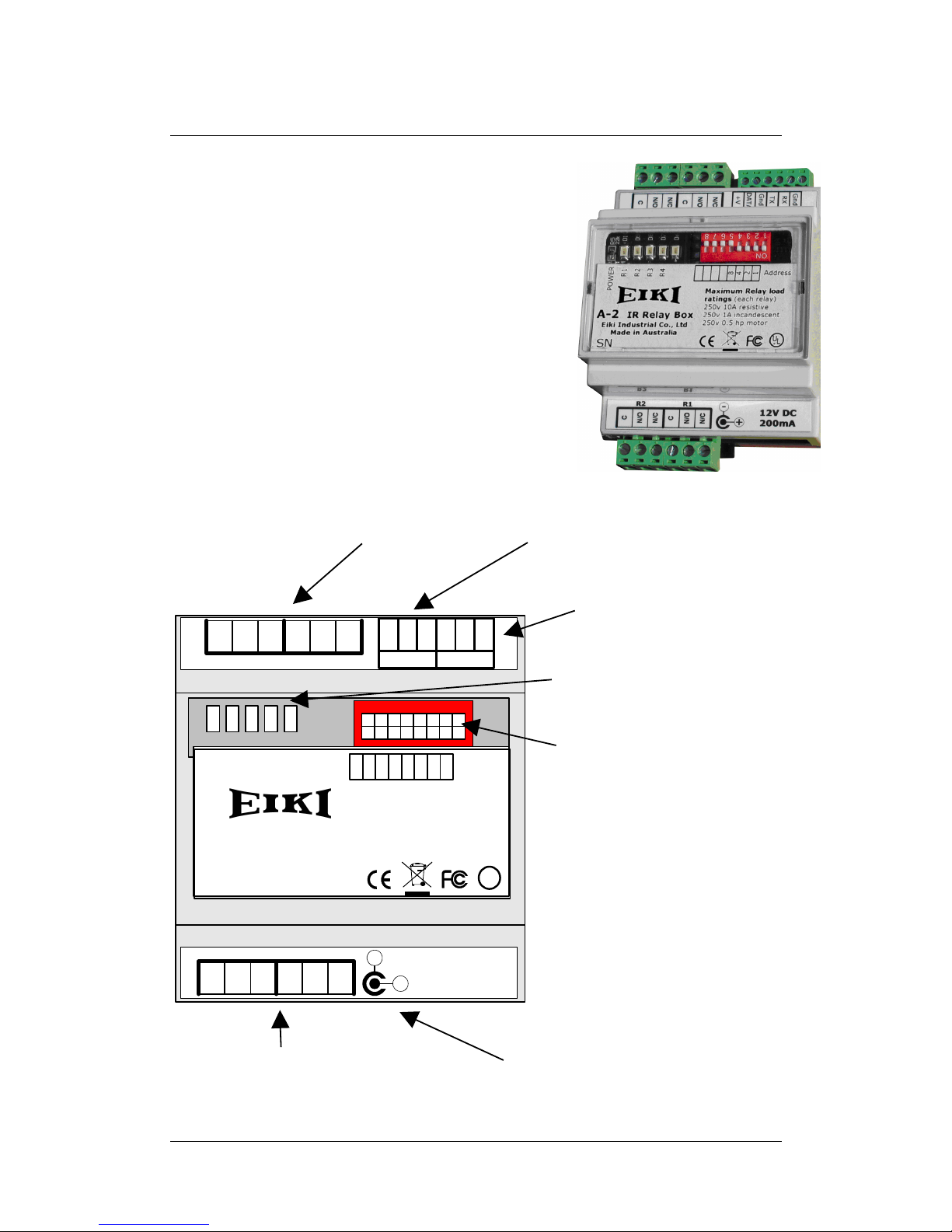
FIG.1. Module view
IR-BusRS232
R4R3
N/C
N/C
N/O
N/O
C
C
Gnd
RX
TX
DATA
+V
Gnd
N/C
N/C
N/O
N/O
C
C
12V DC
200mA
R2 R1
+
Address
A-2
IR Relay Box
Eiki Industrial Co., Ltd
Made in Australia
SN
R4
R3
R2
R1
POWER
1
2
4
8
U
L
®
Maximum Relay load
ratings (each rel ay)
250v 10A resistive
250v 1A incandescent
250v 0.5 hp motor
Relay
connections
IRBus connection – IR receiver or
control panel connects here.
RS232
connection
Unit Address
dipswitch
Indicator LEDs
Relay
connections
DC
Page 4

Eiki A-2 manual Page 4
Operation.
You can control an A-2 IR Relay Box by IR codes that are available in the Eiki
Control System Editor. This is very easy – if you choose the IR Relay Box as the
codeset, the commands are listed for you in the editor. You will not have to refer
to the table below.
You can also control an A-2 from 3
rd
-party equipment or a PC using RS-232.
Whether using IR or RS-232, you can assign each A-2 IR relay box a unique
address between 0 and 15 by using the dipswitches on the unit. This allows more
than one A-2 to be used in a system.
To control a relay in an A-2, first send a number corresponding to the address of
the unit. Next, send the command for the relay you wish to operate.
Codes from 0 to 15 are interpreted as address codes.
Codes from 16 to 31 are interpreted as command codes.
Table 1. Address and operation key codes
Key code Address Key code Operation
0 Address 0 16 Relay 1 - ON
1 Address 1 17 Relay 2 - ON
2 Address 2 18 Relay 3 - ON
3 Address 3 19 Relay 4 - ON
4 Address 4 20 Relay 1 - OFF
5 Address 5 21 Relay 2 - OFF
6 Address 6 22 Relay 3 - OFF
7 Address 7 23 Relay 4 - OFF
8 Address 8 24 Relay 1 - Momentary
9 Address 9 25 Relay 2 - Momentary
10 Address 10 26 Relay 3 - Momentary
11 Address 11 27 Relay 4 - Momentary
12 Address 12 28 Relay 1 - Toggle
13 Address 13 29 Relay 2 - Toggle
14 Address 14 30 Relay 3 - Toggle
15 Address 15 31 Relay 4 - Toggle
Example: In relay box 5 toggle relay 3 - Key codes: 5 30
ON and OFF operations set the appropriate relay to On or Off.
Momentary sets the relay to its On state for the duration of a key press, with a
minimum period of 0.5 seconds. Once the key is released the relay returns to its
Off state.
Toggle will reverse the relay’s current state. For example, if the relay is currently
On then a Toggle command will switch it Off.
Tip: If you need to send a sequence of relay commands to the same module, it is
sufficient to send the address code once only, at the start of the sequence.
An A-2 will respond to a signal with or without carrier and to a level of 0-5 volts
or greater. This makes it compatible with IR LED driver ports (e.g. from a control
processor) and 3
rd
-party IR receivers and systems as well as IRBus.
Page 5

Eiki A-2 manual Page 5
Table 2. RS-232 codes
RS-232 codes can be used by third-party equipment to control a relay box.
RS-232 codes are sent as 1200 baud, 8 data, 1 stop, no parity. Data is expressed
as hexadecimal, NOT ASCII.
The format is as follows:
<Product ID (2 bytes)> <Command type> <Key number> <checksum>
An A-2 relay box will reply to a successfully received command with “FEh 64h”,
however, you can’t use the A-2’s TxD connection where more than one A-2 is
connected as all units will respond and the ports will clash.
Address RS232 code (HEX) Operation RS232 code (HEX)
0 FE 64 02 00 64 Relay 1 - ON FE 64 02 10 74
1 FE 64 02 01 65 Relay 2 - ON FE 64 02 11 75
2 FE 64 02 02 66 Relay 3 - ON FE 64 02 12 76
3 FE 64 02 03 67 Relay 4 - ON FE 64 02 13 77
4 FE 64 02 04 68 Relay 1 - OFF FE 64 02 14 78
5 FE 64 02 05 69 Relay 2 - OFF FE 64 02 15 79
6 FE 64 02 06 6A Relay 3 - OFF FE 64 02 16 7A
7 FE 64 02 07 6B Relay 4 - OFF FE 64 02 17 7B
8 FE 64 02 08 6C Relay 1 - Momentary FE 64 02 18 7C
9 FE 64 02 09 6D Relay 2 - Momentary FE 64 02 19 7D
10 FE 64 02 0A 6E Relay 3 - Momentary FE 64 02 1A 7E
11 FE 64 02 0B 6F Relay 4 - Momentary FE 64 02 1B 7F
12 FE 64 02 0C 70 Relay 1 - Toggle FE 64 02 1C 00
13 FE 64 02 0D 71 Relay 2 - Toggle FE 64 02 1D 01
14 FE 64 02 0E 72 Relay 3 - Toggle FE 64 02 1E 02
15 FE 64 02 0F 73 Relay 4 - Toggle FE 64 02 1F 03
Example: For relay module 5, toggle relay 3:
Code: FE 64 02 05 69 FE 64 02 1E 02
ON and OFF operations set the appropriate relay to On or Off.
Momentary sets the relay to its On state for 0.5 seconds and returns it to the
Off state. You could send repeated commands to keep a relay on but for this to
work the commands must be sent with a delay of around 300mS to 400mS
between them. It is generally more reliable to use the ON and OFF commands if
extended momentary operation is needed.
Toggle will reverse the relay’s current state. For example, if the relay is currently
On then a Toggle command will switch it Off.
Tip: If you need to send a sequence of relay commands for the same module, it
is sufficient to send the address code once only, at the start of the sequence.
Page 6

Eiki A-2 manual Page 6
Setting the Address Dipswitches
You can control up to 15 IR relay boxes and/or Macro Boxes from a single control
panel. To do this, you must set each unit to a different address. Two units set to
the same address will obviously respond simultaneously.
Do not use address 0 when you have more than one unit – it is a global address.
Conversely, if you are only using a single unit, set its address to 0 and you won’t
need to send address codes.
With all 4 dipswitches off, the address is 0. Switches are numbered 1, 2, 4 and 8.
Switching on a switch adds its number to the address. For example, to set a unit
to address 9, switch on 1 and 8. Switching on all four switches results in an
address of 1 + 2 + 4 + 8 = 15.
After you send an address code, a unit set to that address will continue to
respond to command codes until a different address code is sent.
Installation examples
1. Controlling lights, motorised screen and switching speakers.
Control
Panel and/or
IR receiver
Gnd
Data
+V
Lights
Screen
N A
Power in
L R Common
Amplifier
* It is important for electrical
safety reasons to keep power
wiring and low voltage wiring
(e.g. speakers) separated. Using
the relays on the opposite sides of
the module is recommended.
Maximum load rating:
Resistive - 250 V, 10A
Motor - 250 V, 1/2 HP
Tungsten - 250 V, 1A
IR-BusRS232
R4R3
N/C
N/C
N/O
N/O
C
C
Gnd
RX
TX
DATA
+V
Gnd
N/C
N/C
N/O
N/O
C
C
12V DC
200mA
R2 R1
-
+
1
2
4
8
R4
R3
R2
R1
POWER
Address
Page 7

Eiki A-2 manual Page 7
2. Controlling a reversible DC motor.
3. Connecting multiple IR relay boxes together using the IRBus.
A-2 IR relay boxes can be powered from the IRBus as well as from the DC In
jack. This allows a number of them to be connected in parallel, using just 3 wires,
and powered from a single 12 volt power supply.
This supply must be capable of supplying enough current to power all units with
(worst case) all relays switched ON. Don’t forget to allow for the supply current of
the control panel you are using.
You cannot reliably power more than 500mA from the IRBus connection via the
DC In jack on a single IR relay box, because there is internal self-resetting overcurrent protection on the IRBus connection inside each unit. However, if you do
power IR relay boxes from the IRBus, there is limited reverse polarity protection,
so use care when wiring.
+
DC
Motor
-
+
DC
power
supply
-
IR-BusRS232
R4R3
N/C
N/C
N/O
N/O
C
C
Gnd
RX
TX
DATA
+V
Gnd
N/C
N/C
N/O
N/O
C
C
12V DC
200mA
R2 R1
-
+
1
2
4
8
R4
R3
R2
R1
POWER
Address
* Control panel
and module 12v
in wiring is not
shown for clarity.
To use:
Switch on relay 1
for Forward, relay
2 for Reverse.
12 volts
DC @ +
1 amp
Control panel
Gnd Data +12v
IR-BusRS232
R4R3
N/C
N/C
N/O
N/O
C
C
Gnd
RX
TX
DATA
+V
Gnd
N/C
N/C
N/O
N/O
C
C
12V DC
200mA
R2 R1
+
Address
A-2
IR Relay Box
Eiki Industrial Co ., Ltd
Made in Australia
SN
R4R3R2
R1
POWER
124
8
U
L
®
Maximum Relay load
ratings (each relay)
250v 10A resistiv e
250v 1A incandescent
250v 0.5 hp motor
IR-BusRS232
R4R3
N/C
N/C
N/O
N/O
C
C
Gnd
RX
TX
DATA
+V
Gnd
N/C
N/C
N/O
N/O
C
C
12V DC
200mA
R2 R1
+
Address
A-2
IR Relay Box
Eiki Industrial Co ., Ltd
Made in Australia
SN
R4R3R2
R1
POWER
124
8
U
L
®
Maximum Relay load
ratings (each relay)
250v 10A resistiv e
250v 1A incandescent
250v 0.5 hp motor
IR-BusRS232
R4R3
N/C
N/C
N/O
N/O
C
C
Gnd
RX
TX
DATA
+V
Gnd
N/C
N/C
N/O
N/O
C
C
12V DC
200mA
R2 R1
+
Address
A-2
IR Relay Box
Eiki Industrial Co ., Ltd
Made in Australia
SN
R4R3R2
R1
POWER
124
8
U
L
®
Maximum Relay load
ratings (each relay)
250v 10A resistiv e
250v 1A incandescent
250v 0.5 hp motor
Page 8

Eiki A-2 manual Page 8
U.S.A.
EIKI International, Inc.
30251 Esperanza
Rancho Santa Margarita
CA 92688-2132
U.S.A.
Tel : 800-242-3454 (949)-457-0200
Fax : 800-457-3454 (949)-457-7878
E-Mail : usa@eiki.com
Deutschland & Österreich
EIKI Deutschland GmbH
Am Frauwald 12
65510 Idstein
Deutschland
Tel : 06126-9371-0
Fax : 06126-9371-14
E-Mail : info@eiki.de
Eiki (Shanghai) Co., LTD
1. Dapu Road,
Golden Magnolia Plaza
#2109 Shanghai,
200023 China
Tel : 86-21-5396-0088
Fax : 86-21-5396-0318
E-mail : info@eikichina.com.cn
Canada
EIKI CANADA - Eiki International, Inc.
P.O. Box 156, 310 First St. - Unit 2,
Midland, ON, L4R 4K8, Canada
Tel : 800-563-3454 (705)-527-4084
Fax : 800-567-4069 (705)-527-4087
E-Mail : canada@eiki.com
Eastern Europe
EIKI CZECH spol. s.r.o.
Umělecká 15
170 00 Praha 7
Czech Republic
Tel : +42 02 20570024
+42 02 20571413
Fax : +42 02 20571411
E-Mail : easterneurope@eiki.de
Japan & Worldwide
EIKI Industrial Company Limited.
4-12 Banzai-Cho, Kita-Ku, Osaka,
530-0028 Japan
Tel : +81-6-6311-9479
Fax : +81-6-6311-8486
E-Mail : japan@eiki.com
For the latest software and information go to:
WorldWide Website http://www.eiki.com
 Loading...