

EIJKELKAMP WS-GP2 Quick Start Manual
16.92 Weather Station
WS-GP2 Weather Station for wind speed and direction, relative
humidity, air and soil temperature, rain and solar radiation
Quick Start Guide
Version 1.0
P.O. Box 4, 6987 ZG Giesbeek
Nijverheidsstraat 30,
6987 EM Giesbeek,
The Netherlands
T +31 313 880200
F +31 313 880299
E info@eijkelkamp.com
I http://www.eijkelkamp.com
Page 2
Introduction
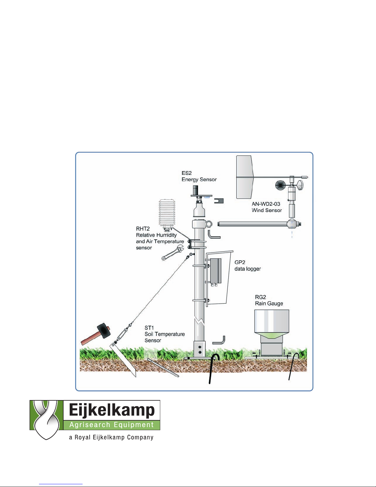
The WS-GP2 Weather Station measures wind speed and direction, air temperature,
relative humidity, solar radiation, rainfall and soil temperat ur e .
This guide explains how to choose a site, install the mast, mount and align the
sensors. Then, using a PC we show how to change the weather station program,
check the sensor readings, then acquire and display readings.
Description
The weather station has a 2m high by 48 mm diameter anodised aluminium mast.
Cross arm, connectors and fitti ngs are provided for sensors and a GP2 data logger.
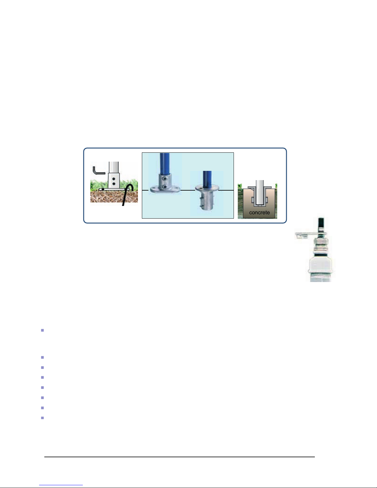
The mast attaches to the ground via the standard base. This may be pinned to the
ground by the stakes provided or bolted down on to concrete or rock.
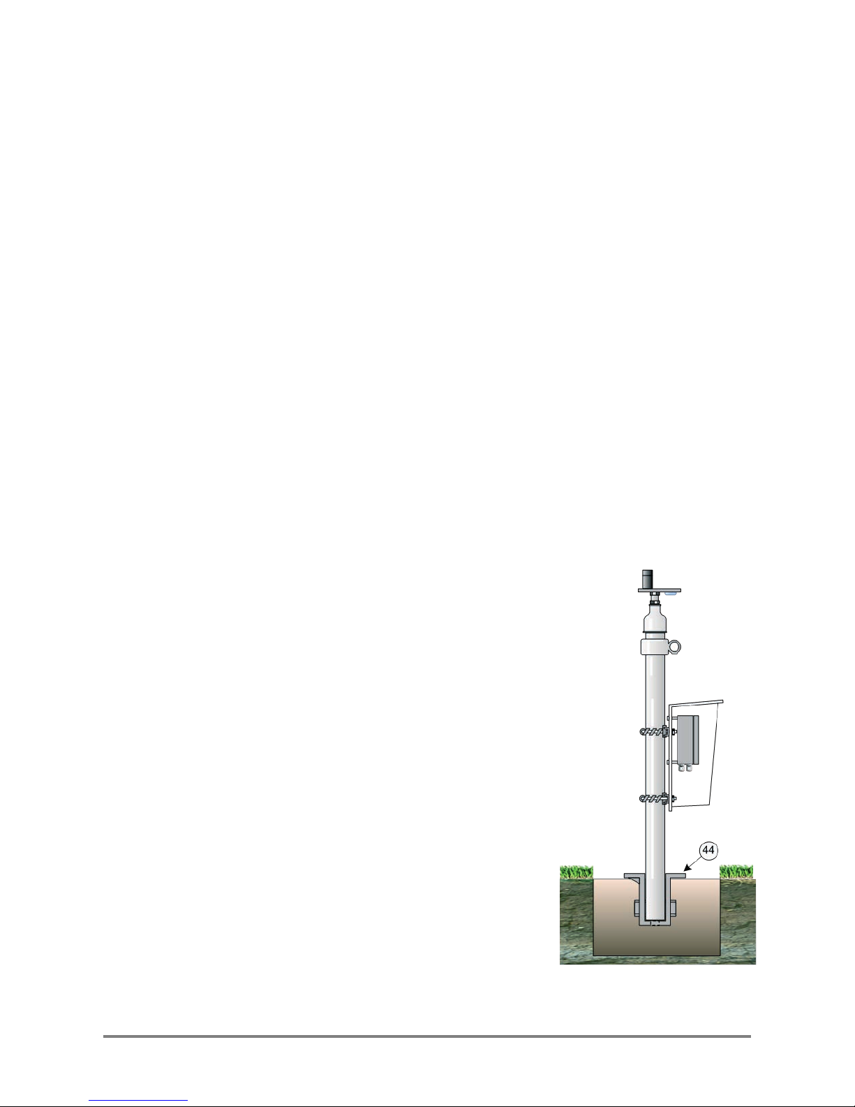
The M2-BASE is an optional extra suitable for fixing into concrete
A levelling mechanism fits on the top of the mast for mounting a type ES2
solar radiation sensor.
The cross arm is installed near the top of the mast and has adapter to take
a combined wind direction and speed sensor.
Below this can fit a bracket holding the combined air temperature and
humidity sensor in a radiation shield.
The RG2-BP rain gauge has a base-plate to be staked level on the ground.
1 Unpacking
Check your contents against your order - you should have:-
M2 mast with cross arm, steel guy ropes, baseplate, stakes, logger can opy , U-
bolts, and GP2 Logger and a logger canopy
See Figure 1 and the Parts Index on page Error! Bookmark not defined.
Wind speed and direction sensor AN-WD2-03
RH and air temperature sensor RHT2nl-03
Solar energy flux sensor ES2-05
Rain gauge RG2+BP-06
Soil Temperature sensor ST1-05
GP2 Logger, with GP2-USB cable and GP2 User Manual
Delta-T Software and Manuals CD including DeltaLINK3
You may need a pic kax e and shovel to prepare the site.
You will need a PC running DeltaLINK3 (supplied with the GP2 logger).
Standard
base
M2-BASE
Page 3
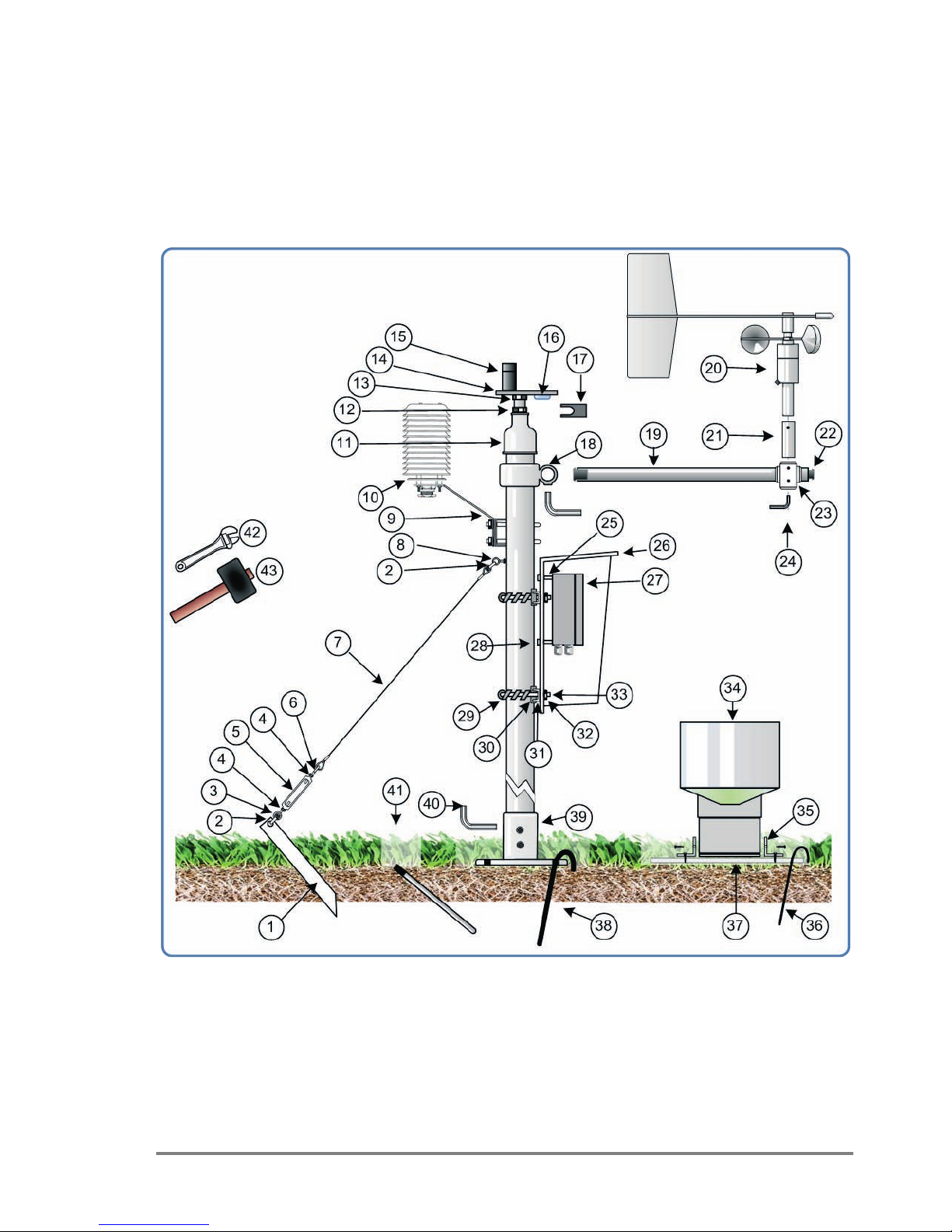
Identify Parts
Figure 1: WS-GP2 Weather Station Mast and Sensor Parts (not to scale)
Page 4
1) Ground stake (x3)
2) D-shackle (x6) size: 3/16 inch
3) Ring bolt (x3) size: M6
4) Lock nut. (x3 s ize: M6
plus x3 with a reverse screw thread)
5) Guy- line tensioning sha ck le /straining screws (x3).
6) Hook bolt (x3
7) Stainless steel guy rope (3x 1.5m)
8) Ring bolt & lock nut (size:M8)
9) Mounting bracket for RHT2 sensor.
10) RHT2 radiation shield.
11) Mast to ball & socket connector
12) Ball & socket levelling device.
13) M8 nut.
14) Levelling plate
15) ES2 solar radiation sensor
16) Bubble level.
17) Spanner for ball and socket device 22mm locknuts
18) Mast to cross arm connector
19) Cross arm (1m x 32mm) with 6.5 mm dia. holes at 4 positions
20) Combined wind speed and direction sensor.
21) Alignment hub
22) Cross arm end pl ug x2.
23) Cross ar m adapter
24) Allen key for cross arm adapter.
25) Stand offs for mounting GP2 to Logger Canopy ( 4x M4 x 15mm)
26) Logger canopy
27) GP2 data logger
28) Logger- canopy conectors
29) Protective spiral wrap for canopy U bolts (x2).
30) Protective strip (x4).
31) U bolt clamp plate (51mm x2)
32) Nuts & washers (x4 size: M6).
33) U Bolts (51mm x2)
34) RG2 rain gauge.
35) Right angle brackets (x2) with self- tapping screws
for mounting RG2 to base-plate.
36) Stakes for RG2 base plate (x4)
37) Base plate for RG 2
38) Stake for M2 Mast base-plate x2
39) M2 mast base
40) Allen key (8mm)
41) ST1 soil temperature probe.
42) Adjustable spanner
43) Mallet
44) Optional extra type M2-BASE for fixing mast in
concrete (7¼ x 5½ inch, internal depth 5 inch)
Page 5
2 Choose the Location
Results depend not just on sensor accura cy and reliability but also on how
representative the site is – so choose the site caref u lly .
Where data is to be compared to a “standard” meteorological site, the sensors should
be exposed in a similar way to sensors at the standard sites, i.e. over a level surface of
short grass and away from tre es or buildi ngs .
These are rough guidelines. Refer to meteorological publications for further advice.
e.g. http://www.wmo.int/web/www/IMOP/WebPortal-AWS/Index02.html
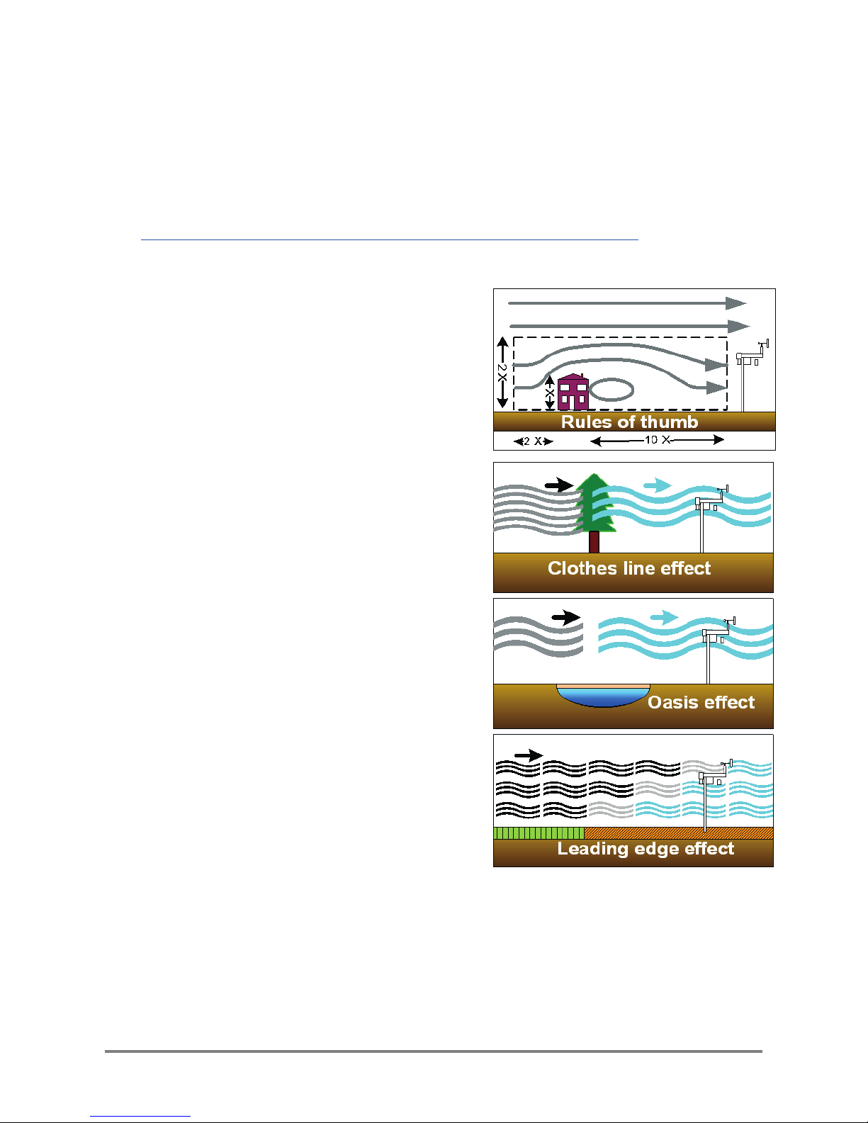
Rules of thumb
Near a building, mount the sensors outside the
zone of influence. Horizontally this extends
roughly twice the height of the building upstream
and ten times downstream. Vertically it extends
to about twice the height of the structure.
If the requirement is to measure the true local
conditions, e.g. a field of newly planted corn,
select a relatively uniform area of the terrain. Be
aware that, as a crop grows up towards the
sensors, the measured wind speed decreases
as the canopy approaches.
Sensors are also influenced by the changing
local thermal and humid ity microclimate above
the crop. There are no simple rules to follow –
but be aware of the following:
Clothes line effect: vegetation upwind may
affect vapour gradients and heat transfer.
Oasis effect: If an isolated source of water, e.g.
a lake or glacier, is surrounded by a relatively
arid area, then the relative humidity may be
affected if the wind direction draws air from the
water source.
Leading Edge effect: When air moves over the
boundary between two s urfaces that differ in
temperature, moisture content, roughness or
some other characteris tic, it takes time for the air
to adjust. The line of discontinuity is known as
the leading edge. The boundary layer will vary in
vertical extent with distance from the leading
edge as it adjusts to the new conditions.
Thermal plume effect: Avoid placing objects
directly under the air humidity and temperature sensor, such as a solar panel, which
can create a rising thermal plume when warmed by the sun.
Figure 2: Location
Page 6
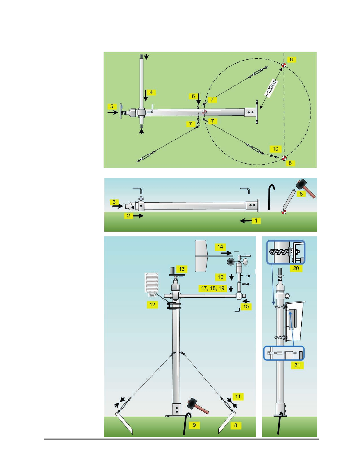
3 Assembly
Figure 4
Steps to
assembly
 Loading...