

EIJKELKAMP PlantControl D, PlantControl CX Operating Instructions Manual
PlantControl D
M1.19.52.E
Wireless Data Logger and Soil Moisture Sensors
Operating Instructions Ver. 3.46
P.O. Box 4, 6987 ZG Giesbeek
Nijverheidsstraat 30,
6987 EM Giesbeek,
The Netherlands
T +31 313 880200
F +31 313 880299
E info@eijkelkamp.com
I http://www.eijkelkamp.com

Contents
1. Introduction 3
Scope of delivery 3
Optional accessories / Optional Functions 3
Basic aspects 4
General features 4
Technical specifications 4
Quick start guide 5
PlantControl front panel 6
PlantControl menu structure 7
PlantControl electrical power connections 7
Introducing the repeater (range extender) 8
Sensor operation 9
Inserting/replacing the batteries 9
Switching on/switching off/testing reception 9
LED display on the sensor 10
Setting the sensor frequency band 10
Replacing the sensor felt 10
2. Commissioning 11
Step 1. Switching on your PlantControl 11
Step 2. Configuring your PlantControl central unit 11
Step 3. Initializing a repeater 12
Step 4. Repeater settings 16
Step 5. Initializing the sensors 17
Step 6. Sensor settings 18
Step 7. Commissioning the GPRS Modem 18
Further PlantControl menu items description 22
Menu Status 22
Menu Sensors 22
Menu Alarms 22
Erase logbook 23
System reset 23
3. Installation 24
Inserting the sensor into the soil 24
4. Moisture output in hPa suction pressure 28
5. Data readout and firmware update 30
Data analyses with PlantCare DataViewer 30
6. Troubleshooting 31
6. Deactivation / Re-Activation 32
Entire system 32
Individual sensors 32
7. Warranty 32
8. Disclaimer 32
9. Support 32
1. Introduction
Please read through these instructions carefully before configuring your PlantControl D central
unit and the soil moisture sensors.
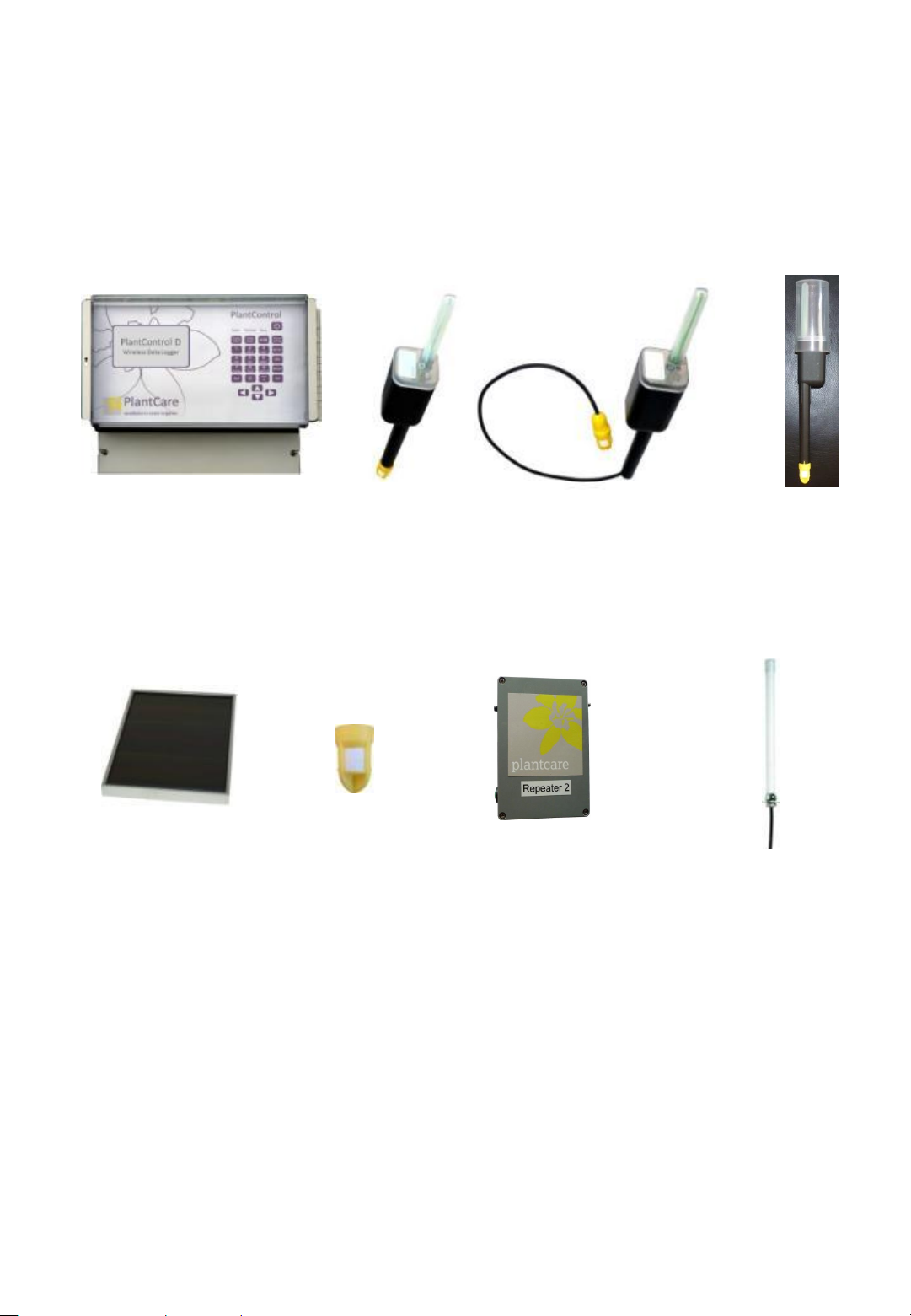
Scope of delivery
PlantControl D central unit (Data Logger)
Wireless soil moisture sensors (quantity and version acc. to order)
PlantCare DataViewer software for the display and analysis of the measured data
PlantControl D central unit
Optional accessories
Solar cell with
cable connection to
the Data Logger
Replacement tip with
felt for sensor (depending on
soil type, different felts
are available)
Optional functions
Wireless sensor
stick version
Wireless sensor
cable version
Repeater
(Range Extender)
Sensor with
protection cap
External antenna for enhanced
signal reception. PlantControl
central unit or GPRS Modem
Remote retrieval function
SMS-Alarm function
3

Basic aspects
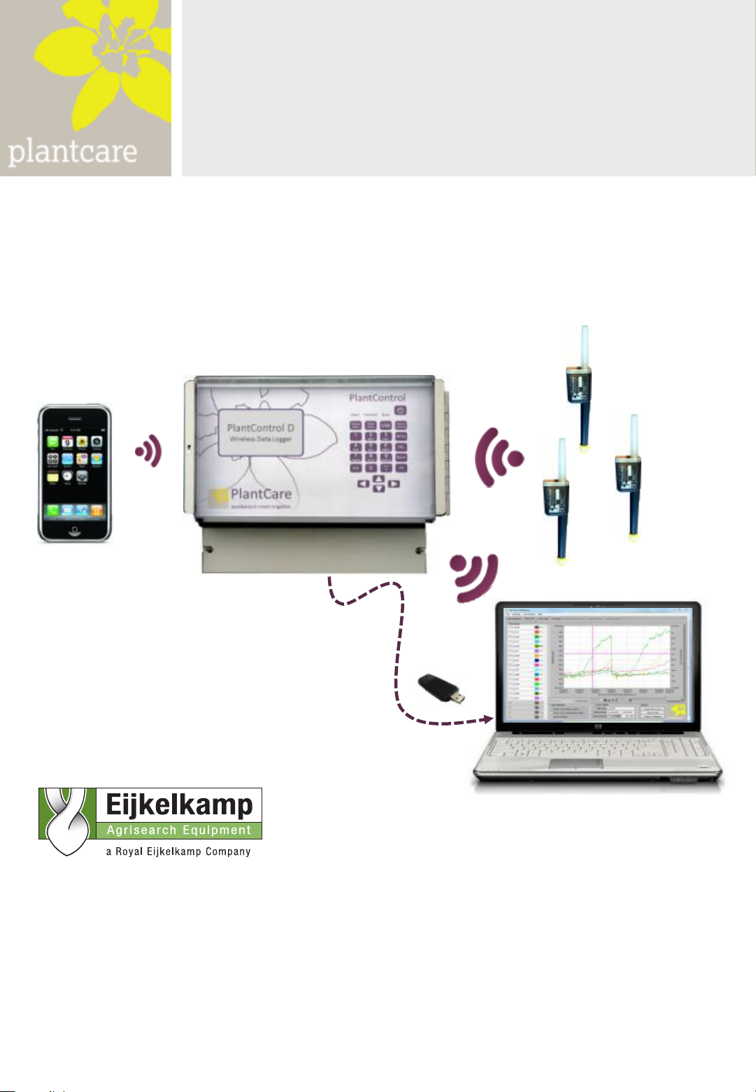
In combination with PlantCare’s wireless soil moisture sensors, the PlantControl D is used for the wireless
monitoring of soil moisture levels and soil temperature for scientific and agricultural applications. A
specially designed software allows the connection of up to 99 sensors, which are synchronized by the
PlantControl D central unit and coordinated. This means that the sensors transmit the measured data
sorted and in the correct sequence within a short period of time. A USB interface allows to export data
very easily. The optional remote retrieval function incl. a GPRS Modem allows the remote retrieval of data
over the mobile network, i.e. over virtually any distance (either automatically and/or by SMS request). In
addition, all relevant system data and alarm messages are transmitted as an E-Mail attachment. With the
optional SMS-Alarm function, alerts are sent by a SMS. A special software (PlantCare DataViewer) allows
quick analysis of irrigation data. Corrective actions can be carried out from a distance without extensive
analysis on the spot.
The worldwide patented PlantCare sensor technology is based on a micro-thermal method of measuring
soil moisture. A specially designed felt material, which is in moisture equilibrium with the soil serves as a
standardized interface between the soil and the sensor. For the measurement of soil moisture, the sensor
is heated for a short time and the cooling time is then determined, which varies depending on the soil
moisture level. The cooling time of the sensor thus provides a reliable indication of the water content in the
soil. The sensors require no maintenance and have no corrosion-prone parts.
In developing the Plant Control D, performance, the ease of use and reliability were given the greatest
priority.
General Features
Up to 99 wireless sensors can be connected.
Weatherproof IP67 housing (central unit and sensors)
Signal range up to 200 meters line-of-sight, dependent on the type of terrain and visual contact
between sensors and the central unit. With optional range extenders, this range can be extended to
several kilometers.
Licence-free transmission frequency: 868 MHz or 915 MHz, interchangeable
Measurement of soil moisture levels and soil temperature at freely selectable intervals.
Measurement in: relative % or hPa (for hPa 6 standard soils to choose from)
Speedily reaction to changes in moisture levels.
Reliable results even at minimum depths (from 5 cm).
Value measured is unaffected by salt or fertilizer content.
Precise recording of measurements through built-in quartz clock in PlantControl D central unit.
The PlantCare DataViewer Software allows an optimal display and analyses of the data.
Various options such as remote retrieval and SMS-Alarm functions are available.
Frost resistant
Operating temperature: -20° C to +50° C
Language setting German/English
Technical specifications PlantControl D
Up to 100.000 data sets can be recorded
USB interface for data export on USB stick
Power supply: 8 AA rechargeable batteries (inclusive), in combination with mains (110/230V)
or solar cell 12W
Dimensions: 29 x 23 x 15 cm
Technical specifications sensors
Can be used in all soil types
Power supply: 2 AA 1.5 V batteries
Battery life span approx. 1 year depending on measuring cycle
Dimensions: 4 x 4 x 29 cm (shortest version)
Available length:
Stick version: 18/35/60/100 cm
Cable version: 60/250 cm (other length available on request)
4

Technical specifications repeater (range extender)
Weatherproof IP67 housing
Signal range sensor to repeater up to 200 meters and repeater to repeater up to 3km (line-of-
sight and dependent on the type of terrain).
Power supply: 8 AA rechargeable batteries (inclusive), in combination with mains (230V AC)
or solar cell
Dimensions: 5.5 x 13 x 17 cm
Sensor measurement data
Moisture display:
• In relative %-units or
• hPa suction pressure for 6 standard soils
Measuring range soil moisture (at a soil temperature between 2° C to +37° C*):
• Relative %-units: 0 - 100%
• hPa: 0 – 400 hPa high sensitivity / > 400 - 800 hPa lower sensitivity
Measuring range soil temperature: -20°C to +50° C
Measuring accuracy:
• Soil moisture: +/- 3%
• Soil temperature: +/- 0.3° C
Reading accuracy:
• Soil moisture in relative %: 1%
• Soil moisture in hPa: 1hPa
• Soil temperature: 0.1 °C
* Sensors for soil moisture measurements at soil temperature range between 2° C to +50° C on request
Quick start guide
At the office
1. Connect cable for mains-connection or solar cell to the PlantControl central unit.
2. Outside Switzerland, pull out security film from the PlantControl central unit (already assembled with
batteries). Insert sensor batteries.
3. Define settings for the PlantControl D central unit: Menu Settings > Controller
4. Initialize repeater (if part of delivery scope): Menu Initialize > Repeater OK-button, hold the button
on the repeater for 5 seconds.
5. Initialize sensors: Menu Initialize > Sensors
6. Define sensor settings: Menu Settings > Sensors
7. For settings of optional functions such as remote retrieval and SMS-Alarm function, go to the
appropriate chapter in this manual.
On-Site:
1. Switch on sensors at the insertion place and check reception strength : Menu Status> Sensors. Insert
afterwards the sensor with the protection cap into the soil.
5
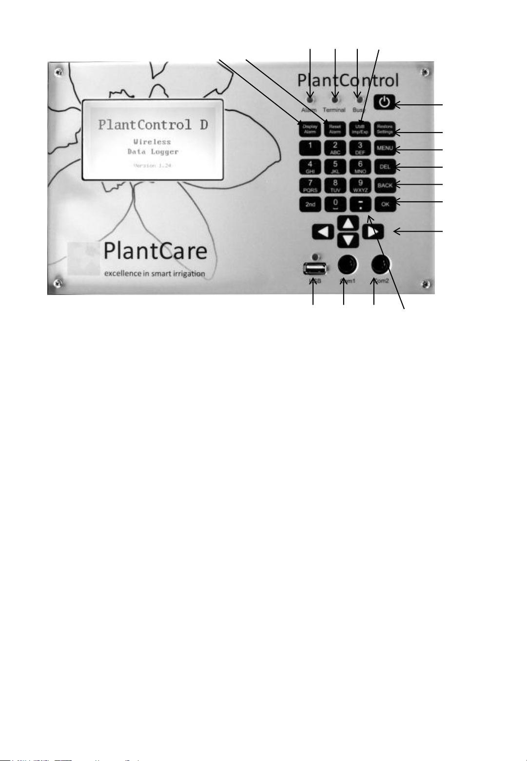
PlantControl: Front Panel
1: ON/OFF key
2: Restore-Settings: not yet activated
3: Main Menu
4: DEL = Deletes last entry
5: BACK = Goes back one menu level
6: OK = Confirm selection or entry
7: Cursor keys
8: Display Alarm: Displays active alarms
9: Reset Alarm: Resets alarms
10: USB Imp/Exp: Button to call the import-export functions via USB interface
11: Alarm-LED
12: GPRS-Terminal-LED: Flashes every 3 seconds when network connection is established
13: Busy-LED: Lights up when the central unit is busy (operating panel is blocked)
14: USB-Interface
15: Service Interface
16: Service Interface
17: Space key: Deletes entries in a text field
Special characters can be found under the key "1" and the "semicolon" key.
Key Lock: By simultaneously pressing the keys "2nd" and "MENU" on or off.
8 9
14 15 16 17
10 11 12 13
1
2
3
4
5
6
7
6
PlantControl Menu Structure
1 Status
2 Sensors
4 Settings
5 Initialize
13 Controller
14 Sensors
29 Identify
41 Controller
42 Sensors
44 GSM/GPRS
45 Repeater
46 Alarms
51 Sensors
54 Repeater
57 Erase logbook
58 System Reset
59 Code Input
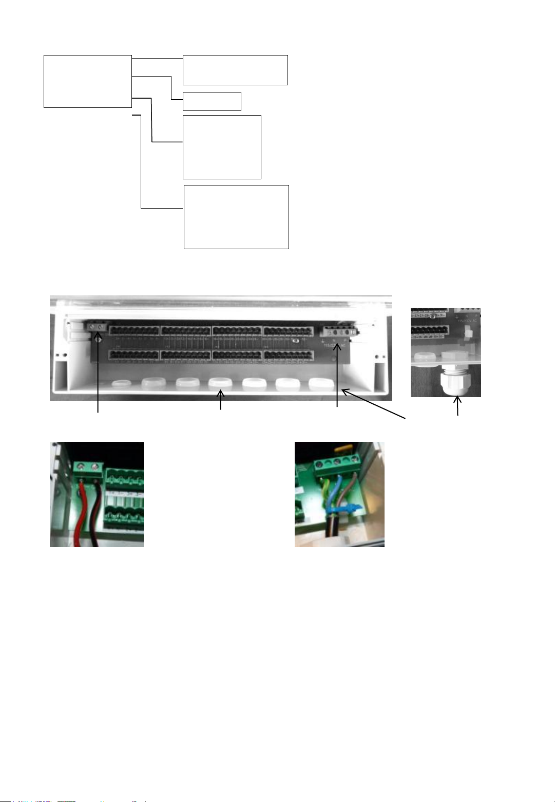
PlantControl Electrical Power Connections
Go to the required menu item by using the cursor
keys. Selectable menu items as well as data entry
fields are shaded in grey. Enter in selected menu
or data field by pressing the OK key.
Connection
solar cell
Please note that no mains plug is included in the delivery, as every country requires its own special plugs. For
each required cable entry, a cable gland is recommended, in order to protect the electronics. Do not connect to
the power supply, unless you have finished the cabling as described below.
To connect your specific mains plug or any other cable connection, please unscrew the lid at the bottom of the
casing.
Mains 115 or 230 VAC: The picture above shows the connection terminals for the mains. Besides the phase
(P) and the neutral line (N) a ground wire has to be used. The power cable is fed through one of the cable
entries and connected to the screw terminal.
Caution: Check first under the menu Settings> Controllers> AC Input, whether 115 or 230 volt is displayed. If
you would like to change the AC input, please contact your supplier.
Solar Cell: The solar cell is connected to the 16V DC screw terminals. For this, the cable is pulled through one
of the cable entries. Connect the black wire to GND and the red wire to 16 VDC.
After finishing the cabling, the cover has to be placed and screwed again. Please make sure that the rubber
seal on the lid as well as the opposite side is not dirty.
Removable plugs
for cable entry
Mains-Connection
115 or 230V AC
Example cable gland
7
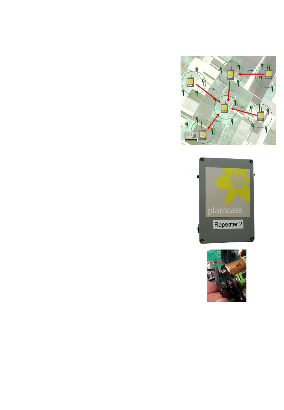
Introducing the Repeater (Range Extender)
Since the signal range between a sensor and the PlantControl central unit is limited to a maximum of 200
meters, repeaters with a signal range of up to 3 kilometers have been developed. If several such
repeaters are used, the signal range can be extended up to 30 km. Power is supplied by either an AC
adapter or a solar cell.
Configuration options
Up to 30 repeaters can be connected with a PlantControl.
Up to 10 repeaters can be connected to each other in a row
(max. 30 km).
Up to 5 repeaters can be connected to one repeater.
Up to 60 sensors can be connected with a repeater.
Note:
The first repeater must be positioned within 200 meters from
the PlantControl.
No sensors may be assigned to the first repeater.
A PlantControl system requires a minimum of two repeaters.
Signal range is up to 3 km line-of-sight and dependent on the
type of terrain.
The repeater frequency band is 868 MHz. Therefore the
PlantControl as well as the sensors must be set to 868 MHz.
Control button / Connections
A. Power connection (power supply or solar cell)
B. LED
C. Control button
D. Interface for external antenna (optional)
A
B
D
Switching on/ switching off/ checking power supply
Please note that repeater are usually delivered with built-in
rechargeable batteries (8x AA).
1. Unscrew the 4 screws and remove the front cover.
2. Attach the battery connector to the battery holder (see picture).
By doing so the repeater is switched on.
3. Mount the front cover.
4. Plug now the AC adapter or solar cell to the power connection.
5. To switch off the repeater the battery connector must be
removed from the battery holder. It is not enough to just pull out
the AC adapter or solar cell cable.
6. Check by pressing the control button, whether the repeater is
receiving sufficient power. If the LED flashes, the repeater is
operational. If the LED does not flash then either there is
currently not enough power available (if a solar cell is used, the
repeater enters in a sleep mode if the battery voltage is < 8.2V in
and is only ready for operation again when the battery voltage
rises again) or the repeater is defective.
Operating (check also chapter "Initializing the repeater")
By pressing the control button, the repeater sends a test
message to the Plant Control. The test Telegram can be used to
identify the repeater (see also Plant Control menu Sensors>
Identify.)
To initialize a repeater, hold down the control button for 5
seconds (see also chapter "Initializing the repeater").
C
8
Sensor operation
Please note that the sensors are usually supplied without installed batteries.
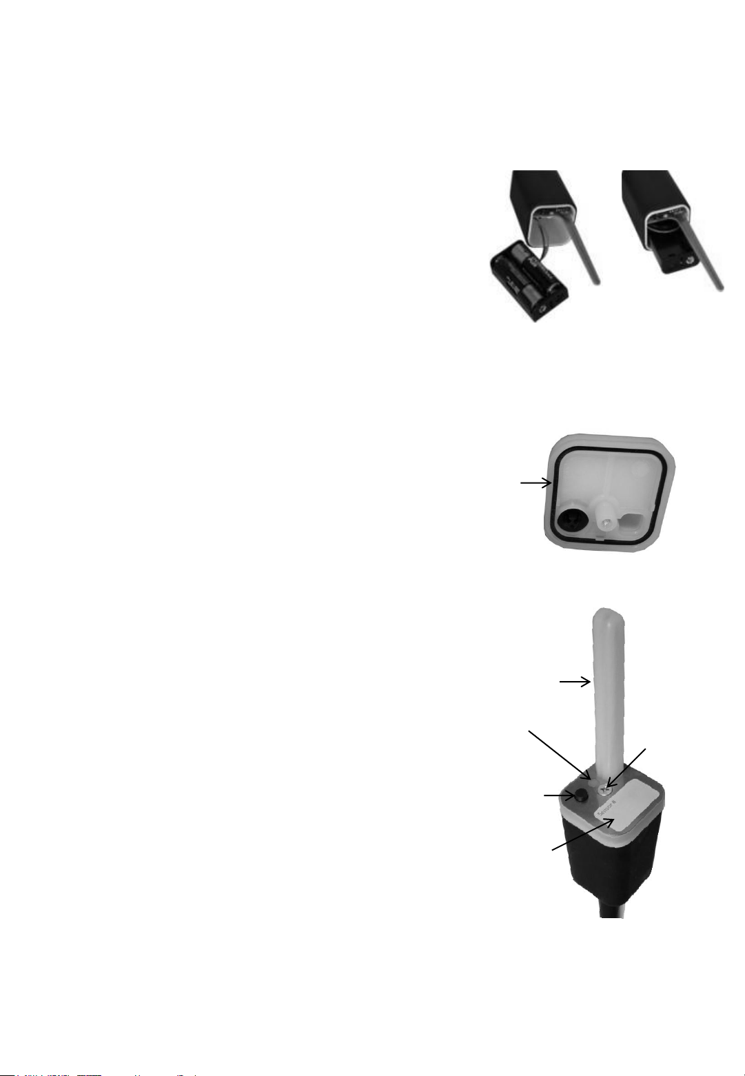
Inserting/replacing the batteries
Switch off the unit if it is still on.
1. Release the retaining screw to remove the sensor cover.
2. Carefully remove the battery holder from the casing.
3. Insert 2 AA batteries. Ensure correct polarity to avoid damaging
the sensor. Dispose of old batteries properly.
4. Reinsert the battery holder carefully into the casing, ensuring
that the wires are positioned between the battery holder and
the partition in the white interior casing.
5. Check if frequency band setting is correct for your country
(Europe generally 868 MHz - see also next page).
6. Replace the cover so that it sits on the white interior casing.
Ensure that the cover seal is located in its groove in the cover
and is free of any dirt. Reattach the cover by tightening the
retaining screw firmly but not too tightly.
7. Switch on the sensor. If the sensor has already been initialized,
all the settings will have been saved and it is ready for use
again immediately.
CAUTION: When you remove
the sensor cover, take care
to put it back on the same
sensor.
Switching on/ switching off/ testing reception
Switching on: Briefly press the ON/OFF button. The LED
will flash for a moment.
Switching off: Depress the ON/OFF button until the LED
lights up and goes out. Then release the button.
IMPORTANT: The sensor cannot be switched off if a
measurement is being taken. If so, wait for 2-3 minutes
and try again.
Testing reception
This is only possible if the sensor has been switched on
and already initialized and if moisture measuring is not
taking place:
Briefly press the ON/OFF button. The LED will flash for a
moment and a test telegram sent to the PlantControl.
After a few seconds, the reception strength and other data
can be read off the PlantControl display in Status >
Sensors.
On completion of a successful transmission, the LED will
briefly flash twice. Otherwise the LED will light up for 1
second.
Use this function, for example, when repositioning a
sensor.
Cover
Gasket
Antenna
LED Fixing Screw
ON/OFF
Button
Marking
Area
9
LED display on the sensor
Switching on: LED flashes for a moment.
Switching off: LED lights up and goes out.
Successful initialization: LED emits 1 long and 1 short flash.
PlantControl was in initialization mode and the sensor has been initialized successfully.
LED flashes 1x 12 seconds after switching on: Control unit was not in initialization mode and the
sensor has been started successfully.
This is what normally happens if the sensor has previously been initialized successfully and then
switched off and on again.
LED flashes 1x every ½ second after switching on Error:
Sensor has not been initialized yet.
LED stays on continuously Error:
The frequency band switch on the sensor has been changed and no longer matches the frequency
band on the PlantControl unit (switch off the sensor/correct the frequency band on the sensor/switch
on the sensor).
LED flashes continuously 2x in quick succession Error:
Replace batteries.
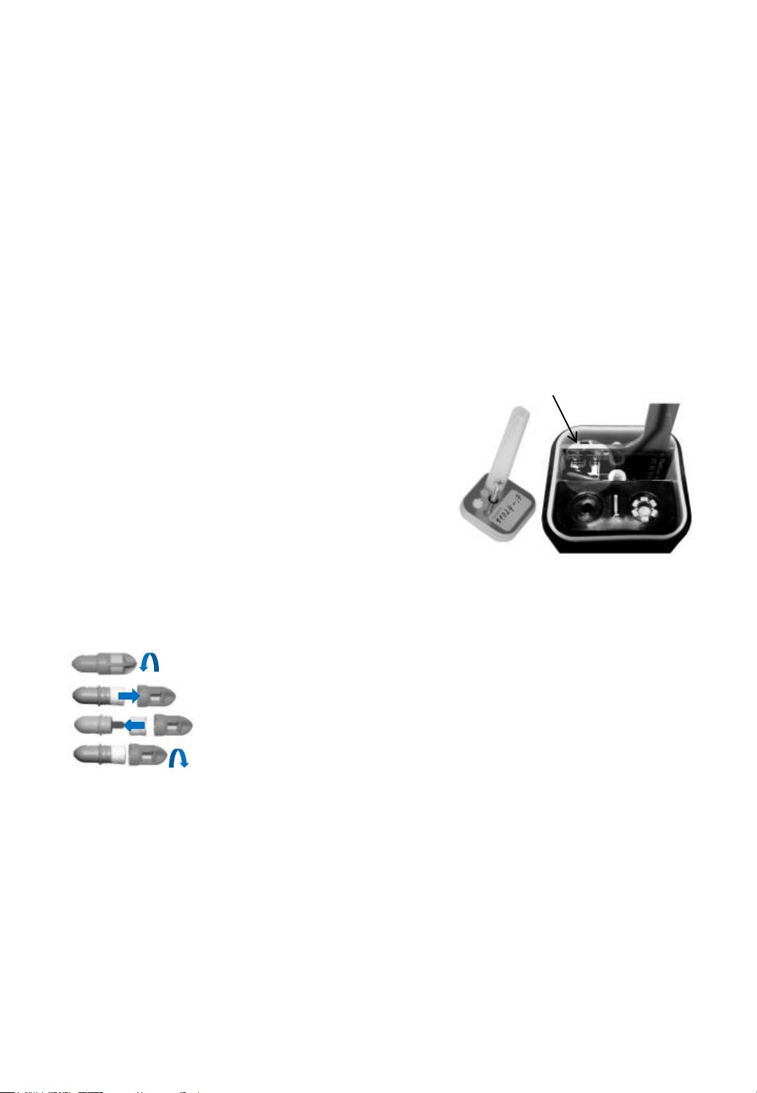
Frequency band 868/915 MHz
sliding switch
Setting the sensor frequency band
The frequency band must have the same setting as
defined in the controller. Q.v. also Settings > Controller >
“Frequency band”
The factory setting for the frequency band is 868 MHz.
1. Switch off the sensor and unscrew the retaining
screw to remove the sensor cover.
2. Use the sliding switch to set the frequency band
permitted in your country. The frequencies are
marked on the PCB.
Replacing the sensor felt
10
 Loading...