

EIJKELKAMP 09.06 Operating Instructions Manual
OPERATING INSTRUCTIONS
09.06 RAINFALL SIMULATOR
A
B
C
Contents
On these operating instructions ....................................................................................................................... 2
1 Description.................................................................................................................................................. 2
1.1 Rainfall simulator .............................................................................................................................. 2
1.2 Accessories....................................................................................................................................... 3
2 Technical specifications ............................................................................................................................... 4
3 Safety instructions ...................................................................................................................................... 4
4 Calibration .................................................................................................................................................. 4
5 Installation .................................................................................................................................................. 6
6 The use .................................................................................................................................................... 6
7 Application .................................................................................................................................................. 6
8 Troubleshooting........................................................................................................................................... 6
9 Maintenance ............................................................................................................................................... 7
P.O. Box 4, 6987 ZG Giesbeek, NL
T +31 313 880200
F +31 313 880299
E eijkelkamp@eijkelkamp.com
www.eijkelkamp.com
1
M1.09.06.E© March 2005
On these operating instructions
!
If the text follows a mark (as shown on the left), this means that an important instruction
follows.
If the text follows a mark (as shown on the left), this means that an important warning
follows relating to danger to the user or damage to the apparatus.The user is always
responsible for its own personal protection.
1 Description
With the rainfall simulator, one measures the runoff and soil loss generated by a standardised rainshower on a
plot with standard surface area. The duration, intensity and kinetic energy of the shower are such that a high
sensitivity of the test results for differences in soil properties is obtained.
1.1 Rainfall simulator
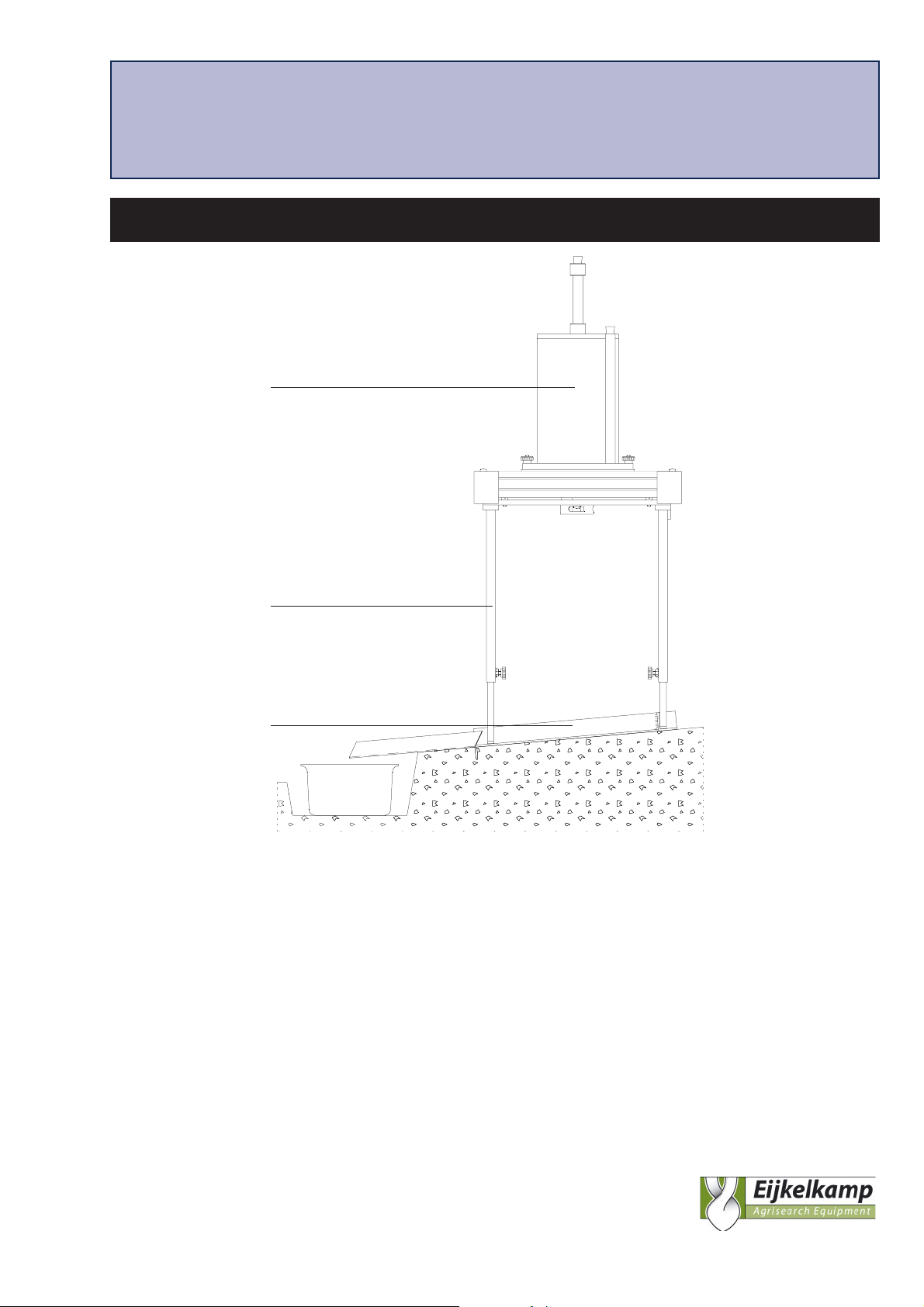
Essentially the rainfall simulator consists of three parts (see figure page 1):
A sprinkler (A) with a built-in pressure regulator for the production of the standard rain shower.
An adjustable support (B) for the sprinkler.
An aluminium ground frame (C), which is placed on the soil and prevents the lateral movement of water
from the test plot to the surrounding soil.
1
2
9
3
10
4
5
6
7
8
11
12
14
h
2

Sprinkler
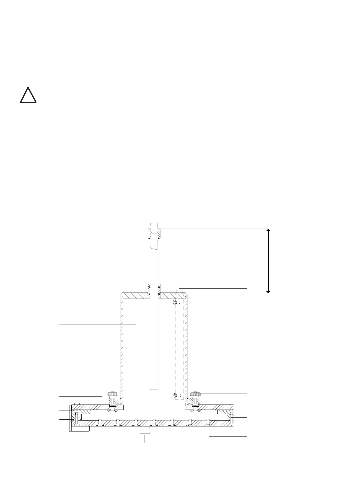
The sprinkler (A) consists of a calibrated cylindrical reservoir (3) with a capacity of approximately 2300 ml, which is
in open connection with the sprinkling head. The waterlevel can be read on the reading pipe (10) which is closed
using a plug (9). Water is released from the sprinkling head through 49 capillaries (14). The pressure head and the
length and the inner diameter of the capillaries determine the release rate. The pressure head on the capillaries can
be increased or decreased by moving the aeration tube (2) upward or downward. The magnitude of this pressure
head regulation is sufficient to correct for influence of the viscosity of the water used on the discharge rate of the
capillaries. It is meant to control the intensity of the required standard shower. The lower ends of the capillaries are
fitted with a short piece of tubing (7). The inner and outer diameters of this tubing control the drop size and the
drop frequency. The sprinkler can be filled through the filling opening, which is normally closed with a plug (8).
Adjustable support
The adjustable support (B) is used for positioning and levelling the sprinkler. Two levels (16) and four knobs (18)
are used to level the support (B) on which the sprinkler is placed. The stainless steel adjustable legs (17) are
positioned on the ground frame (C).
Ground frame
The aluminium ground frame (C) is fixed on the soil using four large nails. The frame is meant to prevent the
lateral movement of water from the testplot to the surrounding soil.
A gutter (19) is installed on the down stream site of the plot for the collection of the runoff and sediment in
the sample collection box (20).
1.2 Accessories
Soil wetting jar
The soil-wetting jar, a plastic box with perforated lid, is used to wet the plot area before sampling.
Water storage tank
With use of a tube, the water storage tank (21) with contents of 20 liter can be connected to the sprinklers’
filling opening. By doing so, the sprinkler can be filled with water.
Sample collection box
Sample material is collected in the plastic sample box with contents of 2 liter.
Sample bucket
The plastic sample box is used to store and transport the sample material.
Transport case
The rainfall simulator and accessories can be stored or transported in the aluminium transport case (22). The
transport case is equipped with two grips, a hinge, and two locks on which the yellow brass padlock can be
fitted.
2 Technical specifications
3
 Loading...