

Page 1
0197
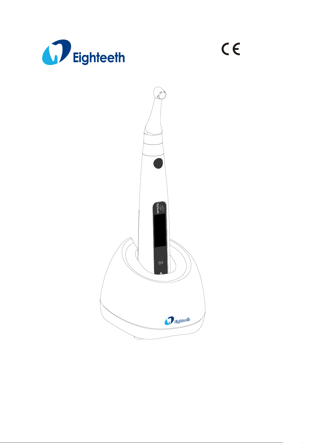
E-connect S
Page 2

Page 2 / 59
USER MANUAL
Page 3

Page 3 / 59
Content
1. Scope of E-connect S ....................................................................................................................... 5
1.1 Parts Identification ............................................................................................................ 5
1.2 Components and Accessories ........................................................................................ 6
1.3 Options (sold separately) ................................................................................................ 6
2. Symbols used in the User Manual ................................................................................................. 8
3. Before Use ......................................................................................................................................... 10
3.1 Intended Use ................................................................................................................... 10
3.2 Contraindications ............................................................................................................ 10
4. Installing the E-connect S ............................................................................................................. 12
4.1 Installation of the contra angle...................................................................................... 13
4.2 Install the file ................................................................................................................... 13
4.3 Connecting measuring wire .......................................................................................... 14
4.4 Connecting charge base ............................................................................................... 14
5. Use Interface ..................................................................................................................................... 17
5.1 Panel key ........................................................................................................................... 18
5.2 Screen display ................................................................................................................... 19
5.3 Terms and definition ......................................................................................................... 23
6. Setting................................................................................................................................................. 25
6.1 Selecting memory ........................................................................................................... 25
6.2 Setting parameters ......................................................................................................... 25
6.3 Preset programs ............................................................................................................. 28
6.4 Advanced setting ............................................................................................................ 30
6.5 Parameter logic ............................................................................................................... 32
7. Operation ........................................................................................................................................... 36
7.1 Charge.............................................................................................................................. 36
7.2 Motor operation ............................................................................................................... 37
7.3 Apex operation and not suitable condition .................................................................. 39
Page 4

Page 4 / 59
8. Maintenance ...................................................................................................................................... 45
9. Error Warning ................................................................................................................................... 48
10. Troubleshooting ............................................................................................................................. 49
11. Technical Data ................................................................................................................................ 52
12. EMC Tables ...................................................................................................................................... 53
13. Statement ......................................................................................................................................... 58
Page 5
Page 5 / 59
1. Scope of E-connect S
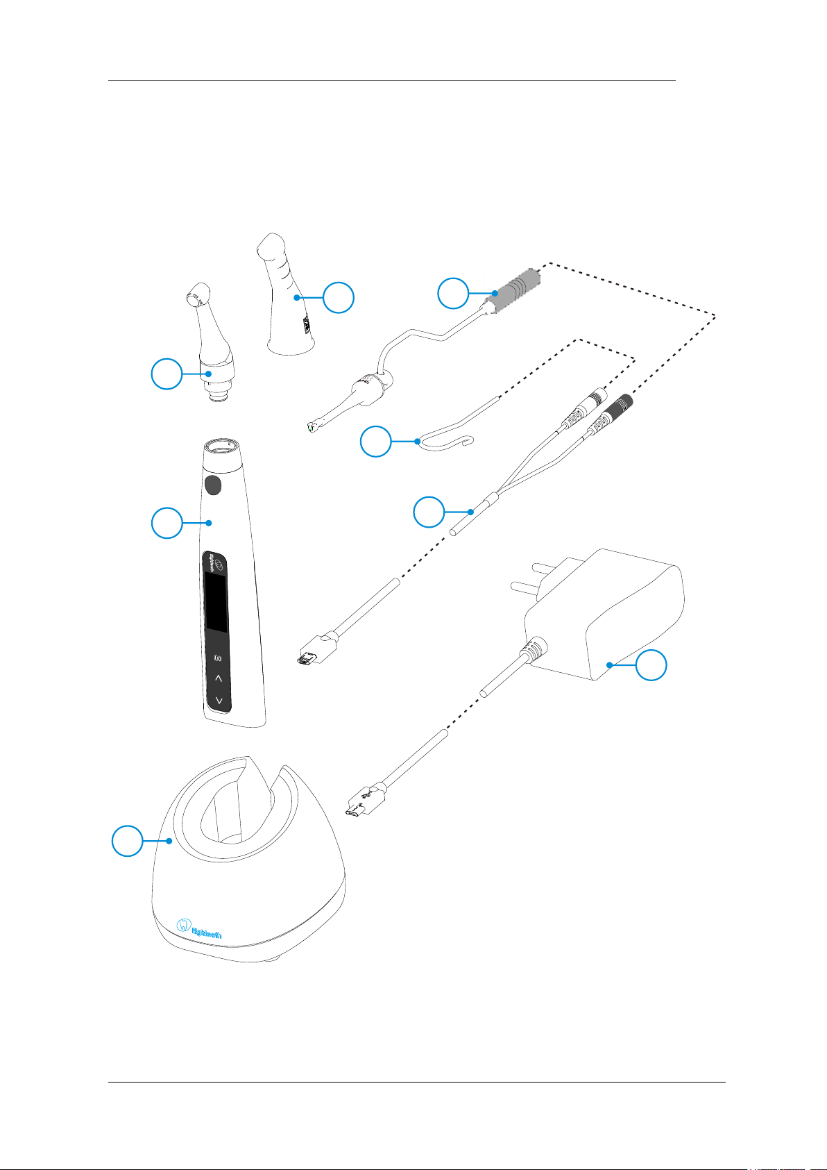
1.1 Parts Identification
1
2
3
4
5
6
7
8
1.Charge Base
2.Handpiece
3.Contra Angle
4.Insulating Sleeve
5.File Clip (2 pcs)
Page 6
Page 6 / 59
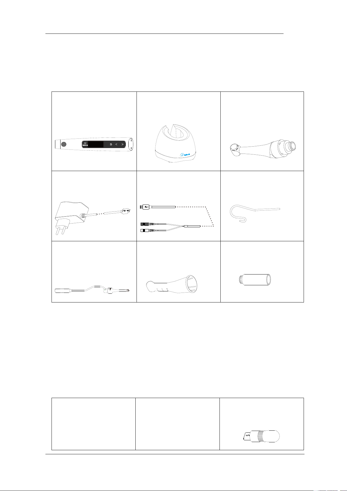
1.2 Components and Accessories
Motor Handpiece (1pcs)
Part No. 6051032
Charge Base (1pcs)
Part No. 6051033
Contra Angle (1pcs)
Part No. 6041003
Adapter (1pcs)
Part No. 6016001
Measuring Wire (1pcs)
Part No. 6015011
Lip Hook (2pcs)
Part No. 6072002
File clip (2pcs)
Part No. 6051005
Insulating Sleeve (1pcs)
Part No. 6004027
Spray Nozzle (1pcs)
Part No. 6051037
1.3 Options (sold separately)
Disposable Sleeve
Part No. 6031009
Handpiece Base
Part No. 6005002
Apex Tester (1pcs)
Part No. 6016001
Page 7

Page 7 / 59
Page 8
Page 8 / 59
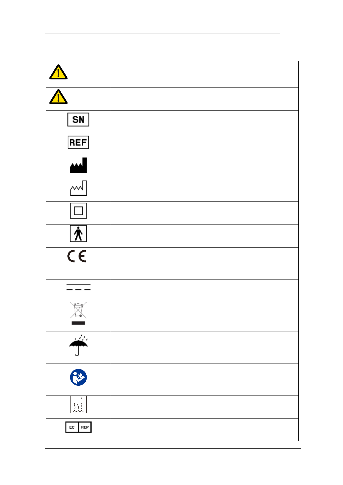
2. Symbols used in the User Manual
WARNING
If the instructions are not followed properly, operation may
lead to hazards for the product or the user/patient.
NOTE
Additional information, explanation of operation and
performance.
Serial number
Catalogue number
Manufacturer
Date of manufacture
Safety class II device
Type BF applied part
0197
CE marking
Direct current
Do not dispose of with normal household waste
Store in a dry place
Consult instructions for use
134 C
Can be autoclaved up to a maximum temperature of 134°
Celsius
Authorized Representative in the European Community
Page 9

Page 9 / 59
Manufacturer’s LOGO
Page 10

Page 10 / 59
3. Before Use
3.1 Intended Use
E-connect S is exclusively designed for dentists for use with dental root canal
instruments in continuous rotation and in reciprocating movement with integrated
apex locator.
This device must only be used in hospital environments, clinics or dental offices
by qualified dental personnel.
3.2 Contraindications
The integrated apex locator of the E-connect S is contraindicated in cases
where patient/user carry medical implants such as pace makers or cochlear implants
etc.
Do not use the device for implants or other non-endodontic dental procedures.
Safety and effectiveness have not been established in pregnant women and
children.
WARNING
Read the following warnings before use:
1. The device must not be placed in humid surroundings or anywhere where it can
come into contact with any type of liquids.
2. Do not expose the device to direct or indirect heat sources. The device must be
operated and stored in a safe environment.
3. The device requires special precautions with regard to electromagnetic
compatibility (EMC) and must be installed and operated in strict compliance with the
EMC information. In particular, do not use the device in the vicinity of fluorescent
lamps, radio transmitters, remote controls, portable or mobile RF communication
devices and do not charge, operate or store at high temperatures. Comply with the
specified operating and storage conditions.
4. Gloves and a rubber dam are compulsory during treatment.
5. If irregularities occur in the device during treatment, switch it off. Contact the
agency.
6. Never open or repair the device yourself,otherwise, void the warranty.
Page 11

Page 11 / 59
Page 12

Page 12 / 59
4. Installing the E-connect S
Page 13
Page 13 / 59
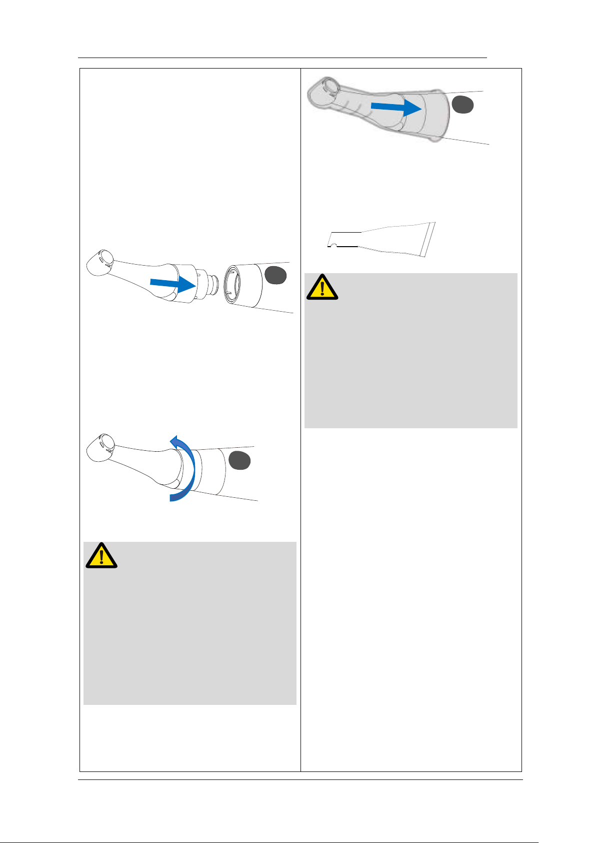
4.1 Installation of the contra
angle
Make sure 4 pins on contra angle
alignment the slots of handpiece, plug
them together until it “click” securely into
place.
The contra angle can be 340 degrees
rotated without take off, make it easy to
watch the LCD in treatment by rotating
the contra-angle.
WARNING
Make sure the assembly is connected
properly, otherwise might cause
unexpected motor reverse, even hurt
the patients
After connecting the contra angle and
handle, pull it gently to make sure the
connection is good.
The improve insulation of the contra
angle during combine apex, we
You can also use disposable sleeve
(sold separately) instead of insulating
sleeve
NOTE
Without the insulating sleeve, when
performing the apex measurement with
handpiece, wear appropriate insulated
gloves, and make sure the contra angle
does not touch the lips. It is advisable to
use a rubber dam when performing
such treatments.
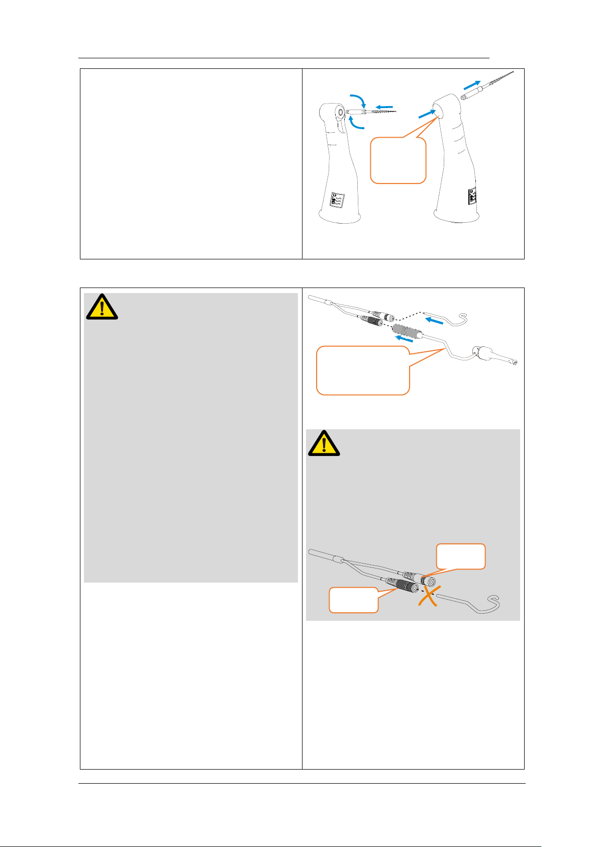
4.2 Install the file
Turn the file back and forth until it is
lined up with interior latch groove and
slips into place, lock the file into the
contra angle.
Hold down the push button on the
contra angle and can release the file.
Page 14
Page 14 / 59
Single apex
function only
recommend using an insulating sleeve.
WARNING
Inspect the file head before inserting the
file. Do not use the damaged file head.
Make sure the motor is stopped when
inserting and removing files.
Be careful when inserting and removing
files to avoid injury to fingers.
Take care not to touch the Main switch
when putting files in. this will cause the
file to rotate.
Pull the file gently to make sure that the
file is secure in handpiece properly,
otherwise it may pop out and hurt the
patient.
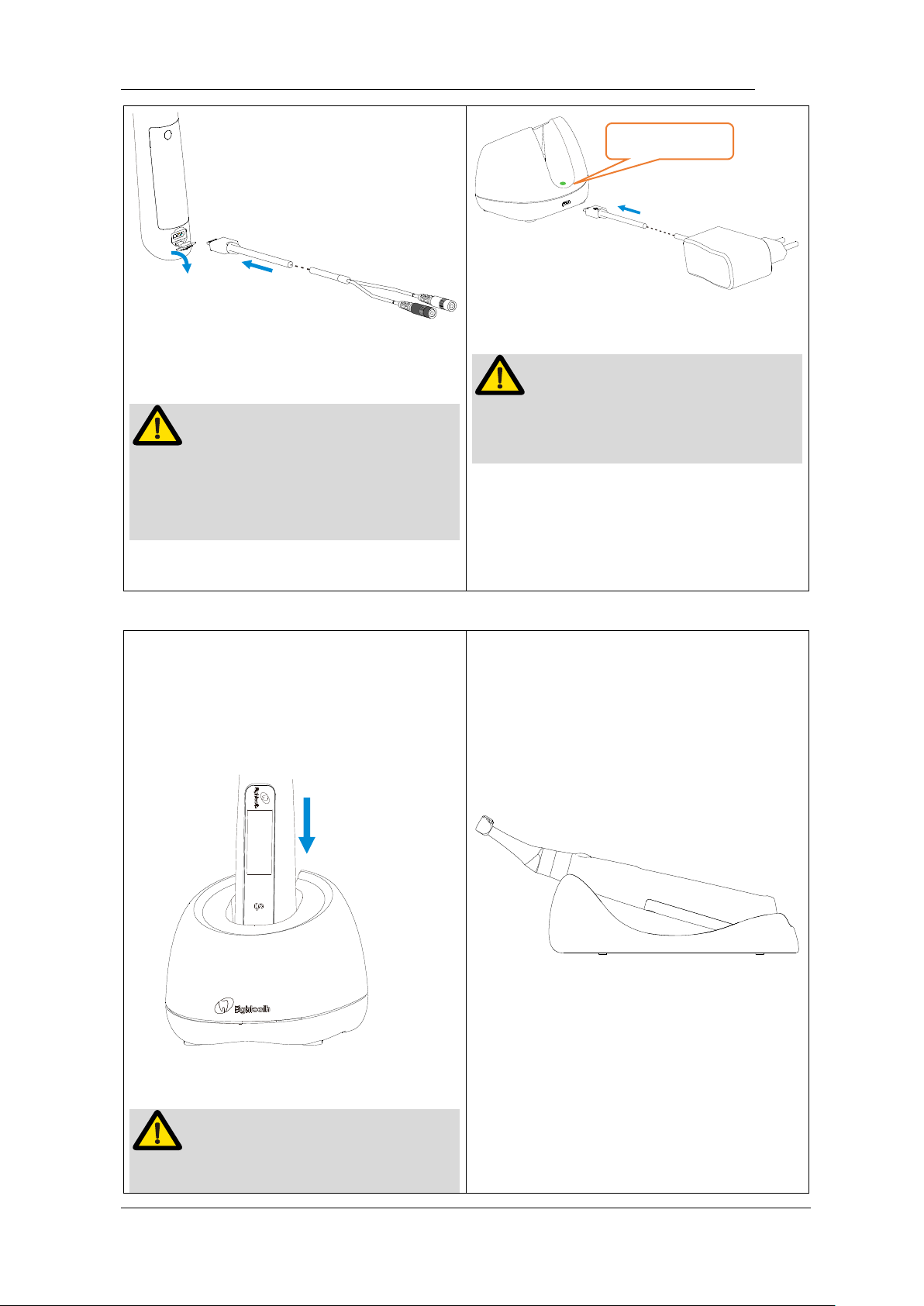
4.3 Connecting measuring
wire
If want activity apex measurement
function, uncap the USB cover on
handpiece, insert measuring wire.
NOTE
Match colors to connect the lip hook and
file clip, if connect lip hook with black
slot, apex auto start will have no
function.
4.4 Connecting charge base
Plug the USB of adapter into the
charge base, and plug the other end
into a power outlet, the Power LED on
charge base will light up (green).
Push
Button
Black
White
Page 15
Page 15 / 59
Insert lip hook into white slot, insert file
clip into black slot.
NOTE
It’s not necessary to connect file clip
during motor combine apex function,
only during single apex function.
NOTE
Only the original adapter could be
used.
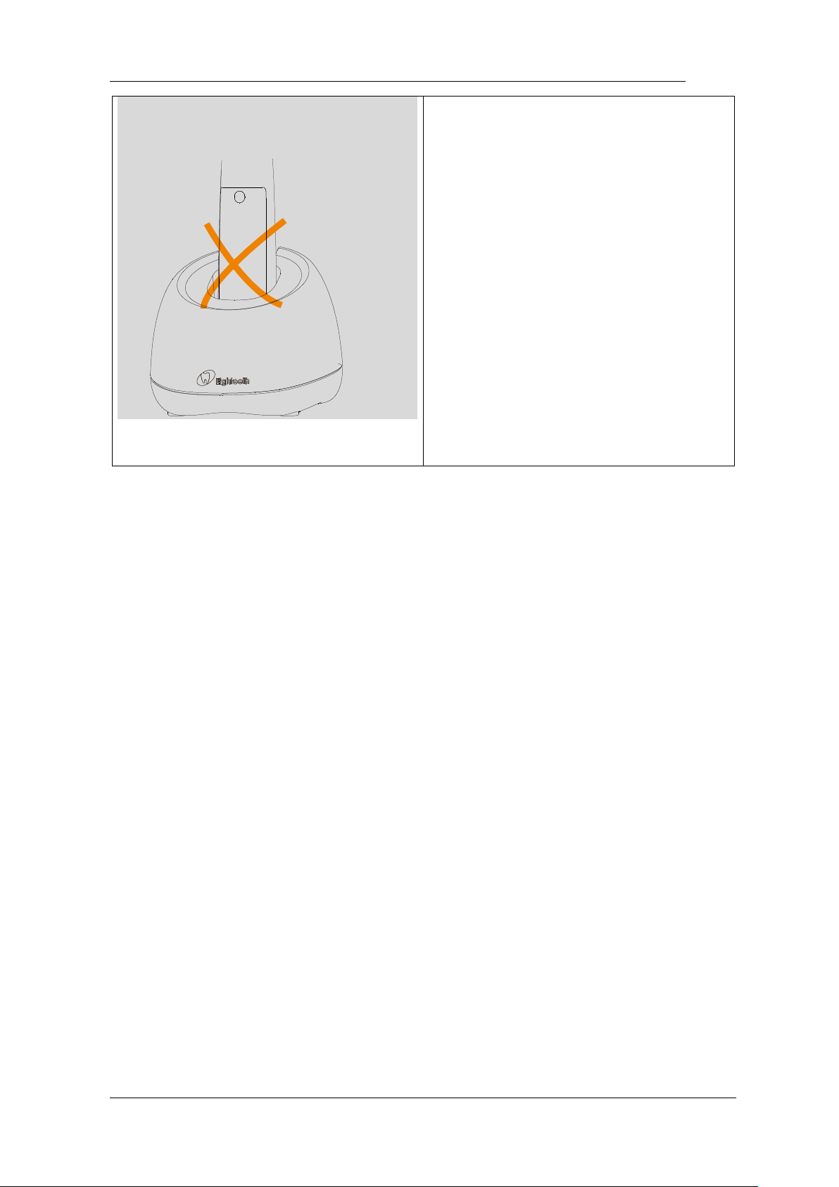
Put the handpiece all the way into the
charge base, the charge state will show
on the screen.
NOTE
Put the handpiece into the charge base
If only need a base to put the device on
dentist element of dental chair ( without
charge function ), handpiece base is
recommended ( sold separately ) to
instead of charge base.
Power LED
Page 16
Page 16 / 59
in the right direction, otherwise the
handpiece will not be recharged.
Page 17

Page 17 / 59
5.Use Interface
Page 18

Page 18 / 59
5.1 Panel key
① ● Main switch
② Display Screen
③ S Setting key
④ < Decrease key
Turn Power On
Press ● more than 0.5 seconds to
turn on the instrument
Memory Change
Press < or > during standby
state
Operation mode Change
Press S once during standby state,
press < or > to change, then
press ● or wait 5 seconds to
confirm
Parameter Adjustment
Press S till target parameters, press
< or > to adjust, then press ●
or wait 5 seconds to confirm
Preset Program Selection
Long press S to entry preset
program during standby state, press
< or > to change, then press ●
to confirm
Turn Power Off
Holding down press S then press
●
Page 19
Page 19 / 59
⑤ > Increase key
Advanced setting
During power off state, holding down
press S then press ● to entry
advanced setting, Press S till target
setting, press < or > to adjust,
then press ● to confirm
5.2 Screen display
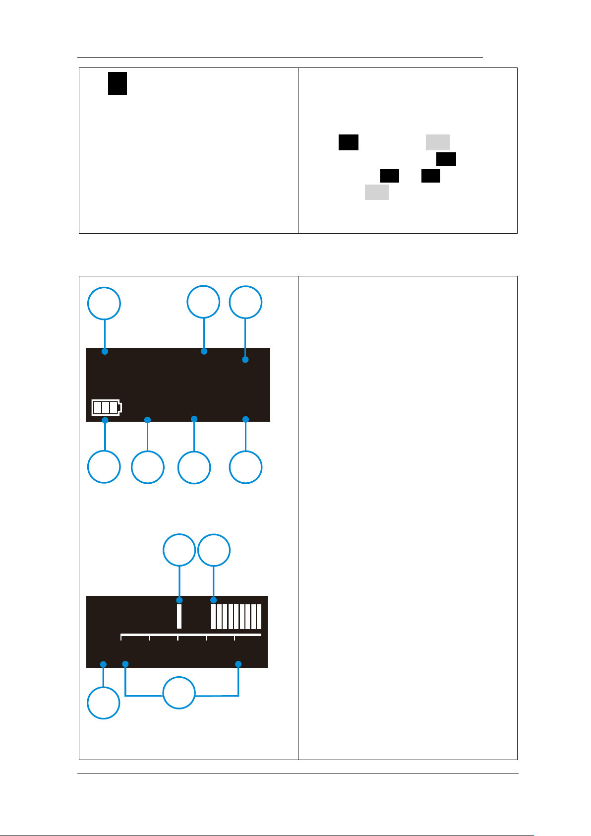
M1
350
rpm
Fwd
Ncm3.0
32
1
4 5 6 7
rpm
N.cm
3
5
0
5
4
3
2
1
1 2
3
4
Standby interface
① Memory mode number
② Speed of this memory
program
③ Unit of speed: Revolutions
Per
minute
④ Residual battery power
⑤ Operation mode
⑥ Torque of this memory
program
⑦ Unit of torque: Newton
centimeter
Standard working mode
Page 20
Page 20 / 59
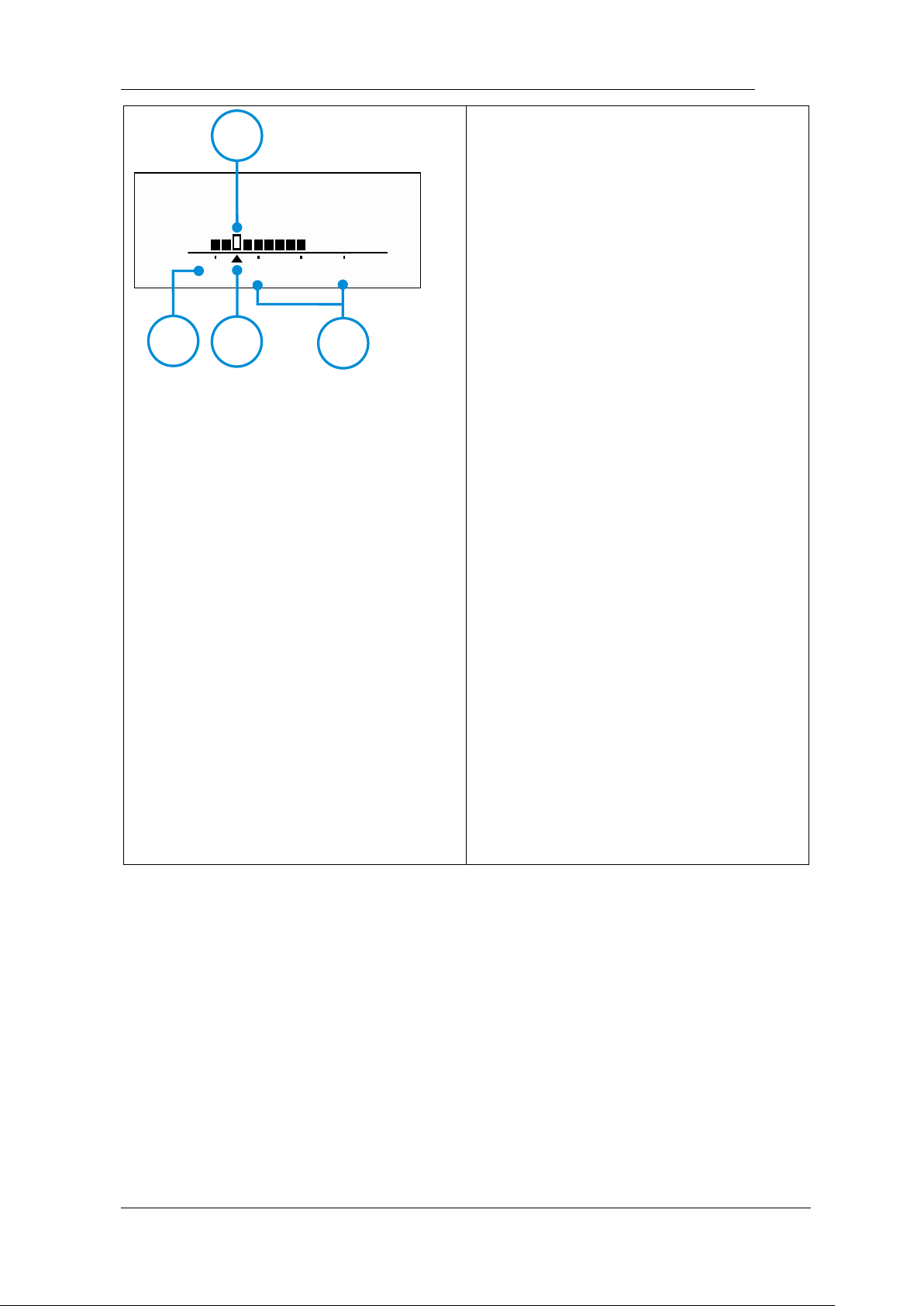
Ref erencepoi nt
AP
1
32
1
2 3
4
① The set maximum torque
② Real time torque
③ Torque display scale
④ The preset speed
Reference point interface
① Flash bar of apical reverse
position
② Apex (Major/Anatomic apical
foramen)
③ 0.5mm meter reading (Very
near Minor/Physiological apical
foramen)
④ 1mm-3mm (Estimate
dimension) distance scale from
apex (Estimate dimension)
Page 21
Page 21 / 59
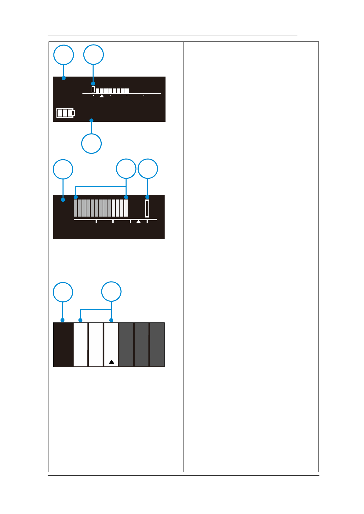
M0
EAL
AP 1 32
1
2
3
3
1
2
0
5
2
A
P
1
3
m m
0
.
5
03020100-
1
0
4
2
1
Canal measurement standby
interface
① Memory mode number
M0 is apex stand-alone memory
② Electronic apex locator
③ Apex flash bar
Canal measurement start interface
① Indication number
The number has no represent of
actual length, only for indication
② Canal length indicator bar
③ Apex flash bar (apex stand-
alone mode) or reference point
flash bar (motor combine with apex
mode)
Canal measurement approach apex
interface
① The estimate dimension from
apex (Major/Anatomic apical
foramen)
② Canal length indicator bar
Page 22

Page 22 / 59
Page 23

Page 23 / 59
5.3 Terms and definition
Fwd
Forward ( Clockwise rotation )
Rev
Reverse ( Counter clockwise rotation )
Be applied to special file, inject calcium hydroxide and other
solutions
REC
Reciprocation
Be applied to reciprocating file, path file and rotary file
protection by setting some special angle
ATC
Adaptive torque control
Up to setting torque, the motor will move with reciprocating
mode; when torque reduce to normal value, the motor will
clockwise rotate
EAL
Electronic apex locator
In the mode, the device will work like a stand-alone apex
locator
AP
Apex
Major apical foramen or Anatomic apical foramen
R.L
Torque reverse less
The motor will not reverse rotation no matter how large the
torque load is
Reference point
During combined length determination, normally apical
reverse must active before reaching major apical foramen,
setting apical reverse position by change the flash bar
FWD Angle
Forward angle (Clockwise rotation angle), activating in REC
and ATC operation mode
REV Angle
Reverse angle (Counter Clockwise rotation angle), activating
in REC and ATC operation mode
Memory Mode
Such as M0-M10
Page 24

Page 24 / 59
Operation Mode
Such as FWD, REV, REC and ATC
Page 25
Page 25 / 59
6.Setting
6.1 Selecting memory
M1
350
rpm
Fwd
Ncm3.0
2
1
3 4
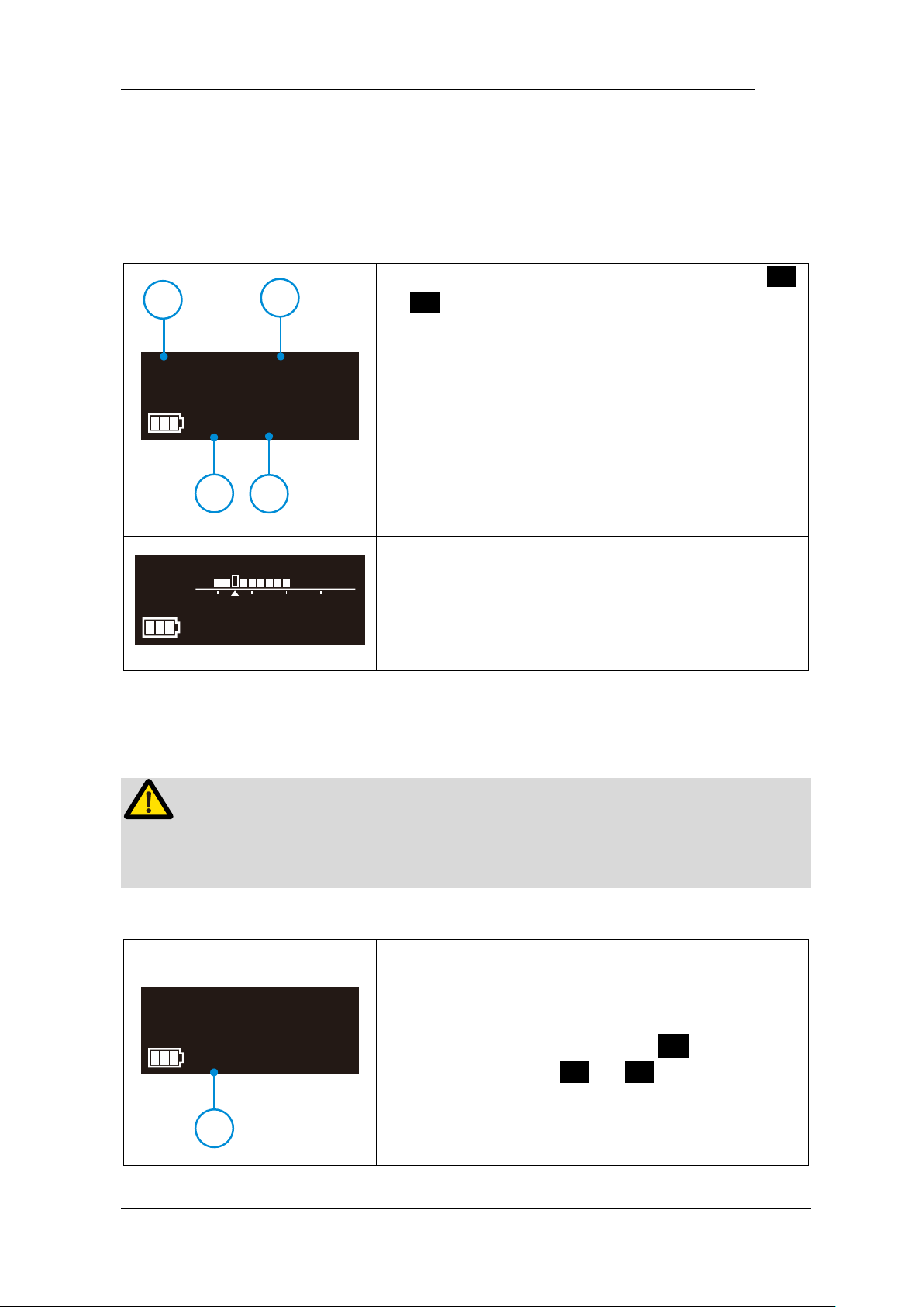
E-connect S has 11 memory programs, press <
or > to change during standby state, the
memory number (○,
1
) will change according.
M1-M10 is standard working memory for canal
shaping, every memory has its own speed (○,2),
mode (○,3) and torque (○,4), all this these
parameters can be changed (See chapter 6.2
Setting parameters).
M0
EAL
AP 1 32
M0 is special memory for stand-alone apex locator
function (See chapter 7.3 Apex operation and
not suitable condition).
6.2 Setting parameters
WARNING
All the parameters must be set according to files, make sure all the parameters are
expected before starting the motor, otherwise has risk of file broken.
M1 350 rpm
Fwd
Ncm
3.0
1
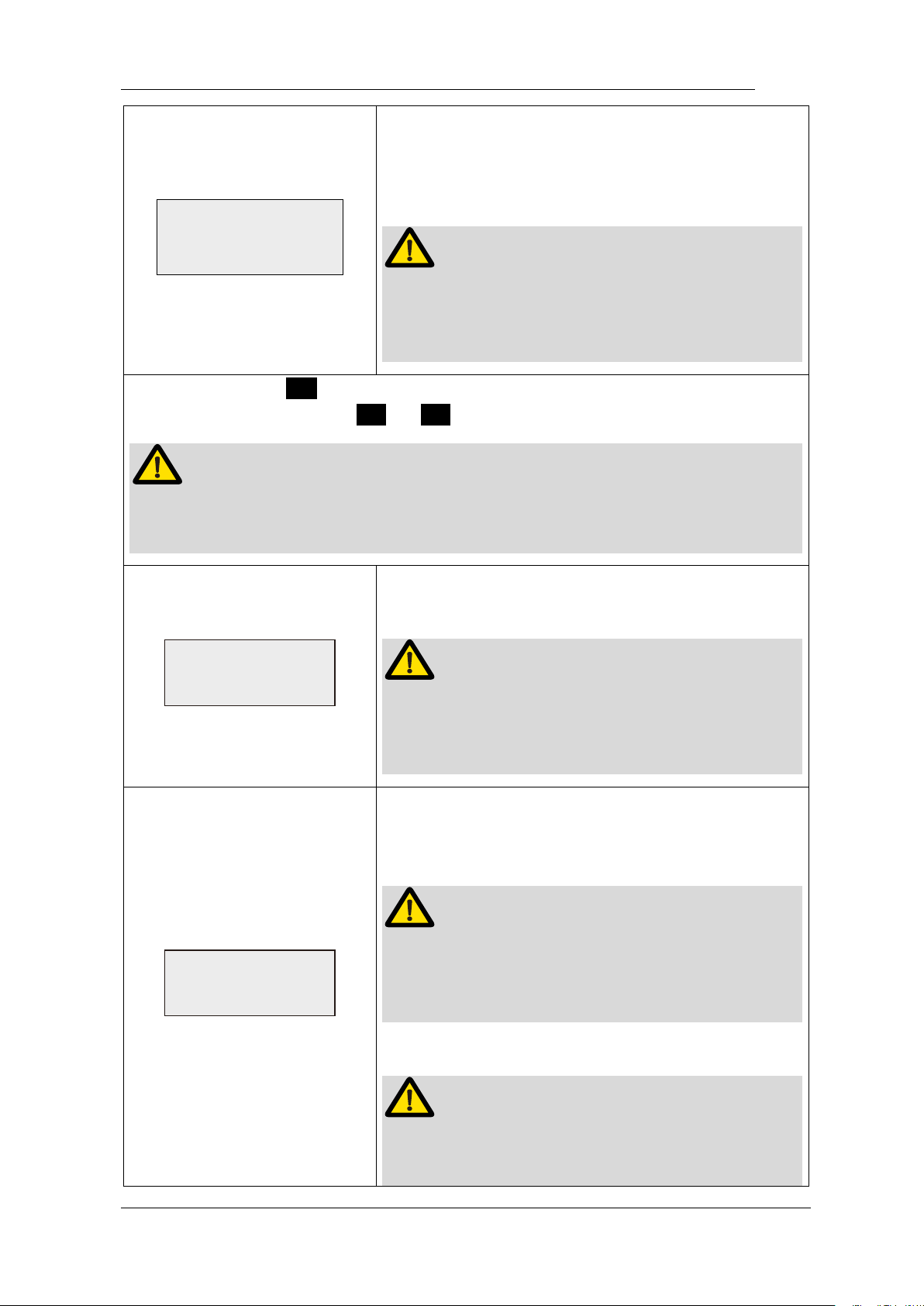
Before start the motor, check the operation mode
(○,1) is correct, otherwise press S once during
standby state, press < or > to change.
Page 26
Page 26 / 59
Oper at i on Mode
Fwd
E-connect S has 4 operation modes: FWD, REV,
REC and ATC (See chapter 5.3 Terms and
definition to get the explanations of these
modes).
NOTE
When choice REV mode, a slow beep alarm
sound appears after starting the motor, used for
indicating counter clockwise rotation happening.
Repeatedly press S to check all the next level parameters of this operation
mode are expected, press < or > to change if not.
NOTE
The parameter will differ in difference mode according to certain logic (See
chapter 6.5 Parameter logic).
Speed
300 rpm
The speed setting can be adjusted from 120 rpm to
1000 rpm.
NOTE
The speed of REC and ATC operation mode is
difference according to certain logic (See chapter
6.5 Parameter logic).
Torque Limit
3.0 Ncm
The torque setting can be adjusted from 0.5 N·cm
to 4.0 N·cm, and R.L (torque reverse less) is also
available.
NOTE
The torque of REC and ATC operation mode is
difference according to certain logic (See chapter
6.5 Parameter logic).
WARNING
When choice R.L (torque reverse less), a slow
beep alarm sound appears after starting the motor.
Page 27
Page 27 / 59
Be careful to use this function, very professional
skill is needed, otherwise has risk of file broken.
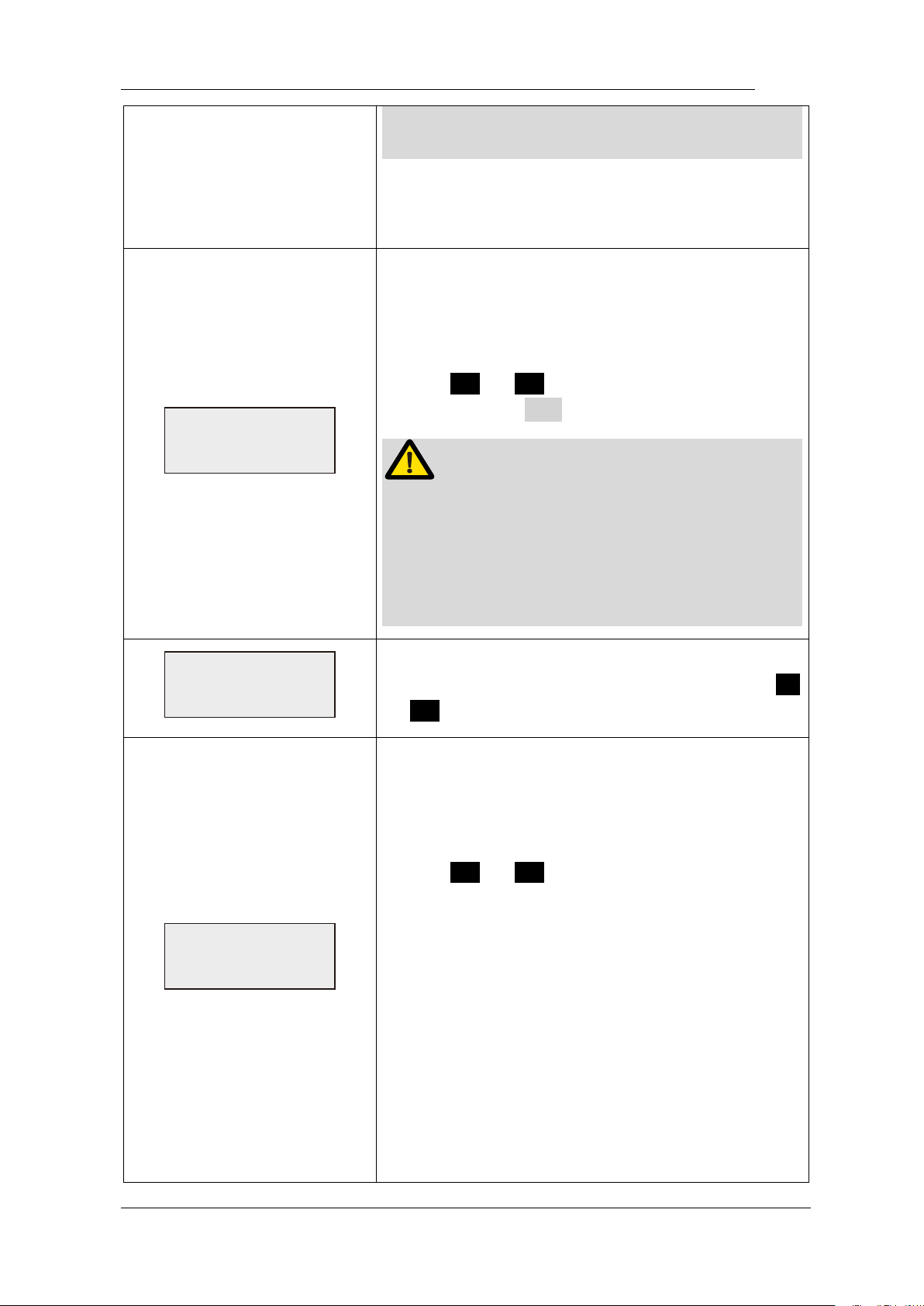
Auto Start
ON
E-connect S integrated apex locator, if the lip hook
is connecting with patient’s lip, when the endo file
entering root canal, the motor will start
automatically.
Press < or > to shut off this function if not
expected, press ● to start and stop the motor.
WARNING
The motor will start automatically if handpiece
(without insulating sleeve) or file touch the
patient’s lip or operator’s fingers (without
insulating glove), take care to avoid this, the file
rotated by motor has risk of injure someone.
Auto Stop
OFF
When the endo file out of root canal, the motor will
not auto stop with default setting, Press <
or > to select auto stop “ON” if needed.
Apical Action
Reverse
Because of integrated apex locator, when the file
reaches the reference point, the motor will
response according to setting, it can be Reverse,
SlowDown, Stop and Off.
Press < or > to change.
Reverse: rotation direction changing till the file
upward a little bit by operator, rotation direction will
change back again.
SlowDown: rotation slowdown when approach the
reference point, will reverse if reach.
Stop: rotation stop when reach the reference point,
upward a little bit and will rotate again.
Off: rotating as usual even if reach the reference
point.
Page 28
Page 28 / 59
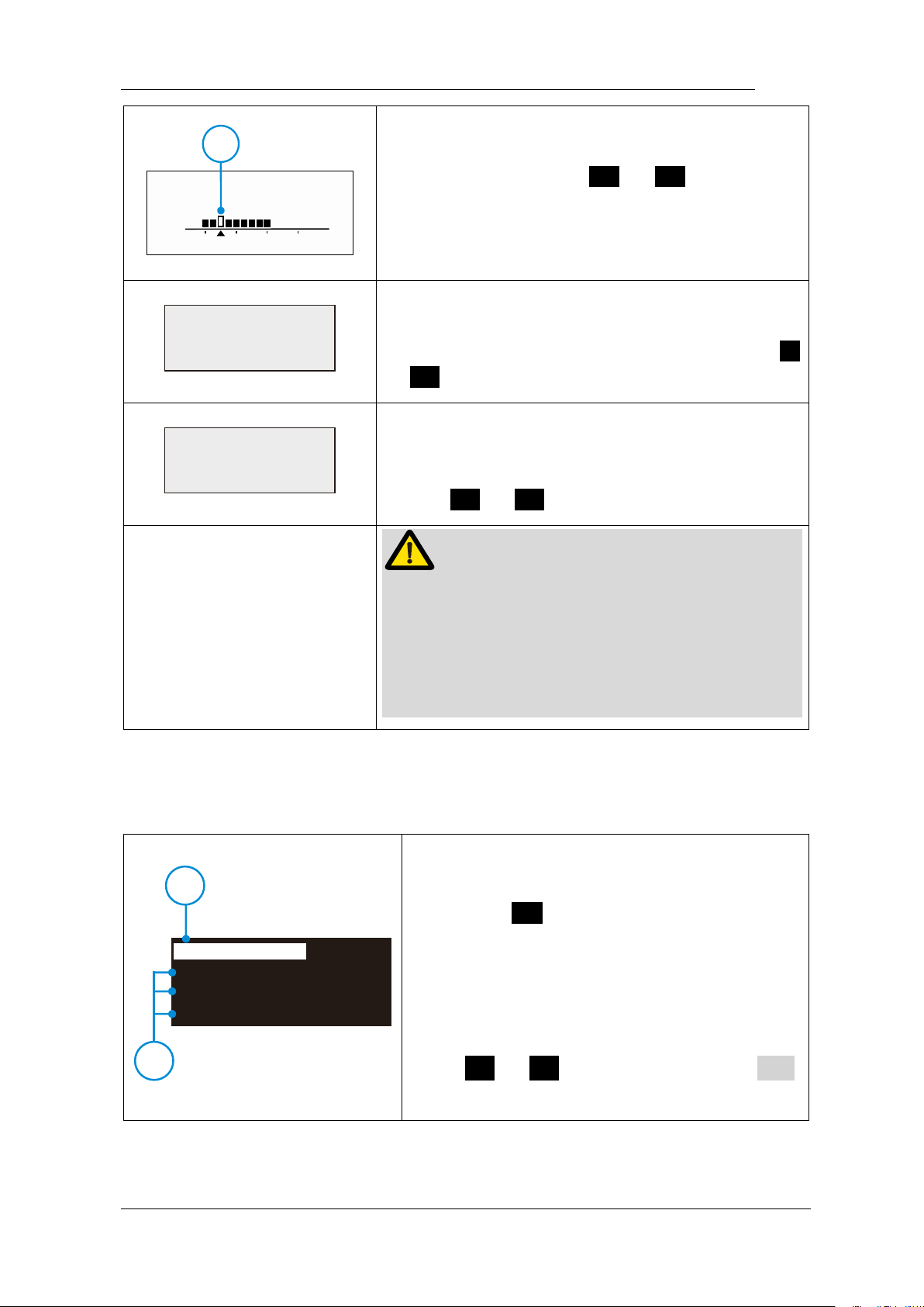
Referencepoi nt
AP
1
32
1
During combined length determination, normally
apical reverse must active before reaching major
apical foramen, Press < or > to set apical
reverse position by change the flash bar (○,1), the
motor will reverse while reaching the flash bar
every time.
FWD Angle
120°
Activating in REC and ATC operation mode.
forward angle (Clockwise rotation angle) can be
adjusted by operator from 30° to 370°, Press <
or > to change.
REV Angle
150°
Activating in REC and ATC operation mode.
reverse angle (Counter Clockwise rotation angle)
can be adjusted by operator from 30° to 370°,
Press < or > to change.
NOTE
The sum of FWD Angle and REV Angle must be
greater than 120°, the motor system has closed
the angle not needed. For example: if you set
FWD Angle 30°, the REV Angle must be setting
greater than 90°.
6.3 Preset programs
350 rpm
CW
Ncm3.0
1
2
M1
Protaper SX&S1
Protaper S2
Protaper F1
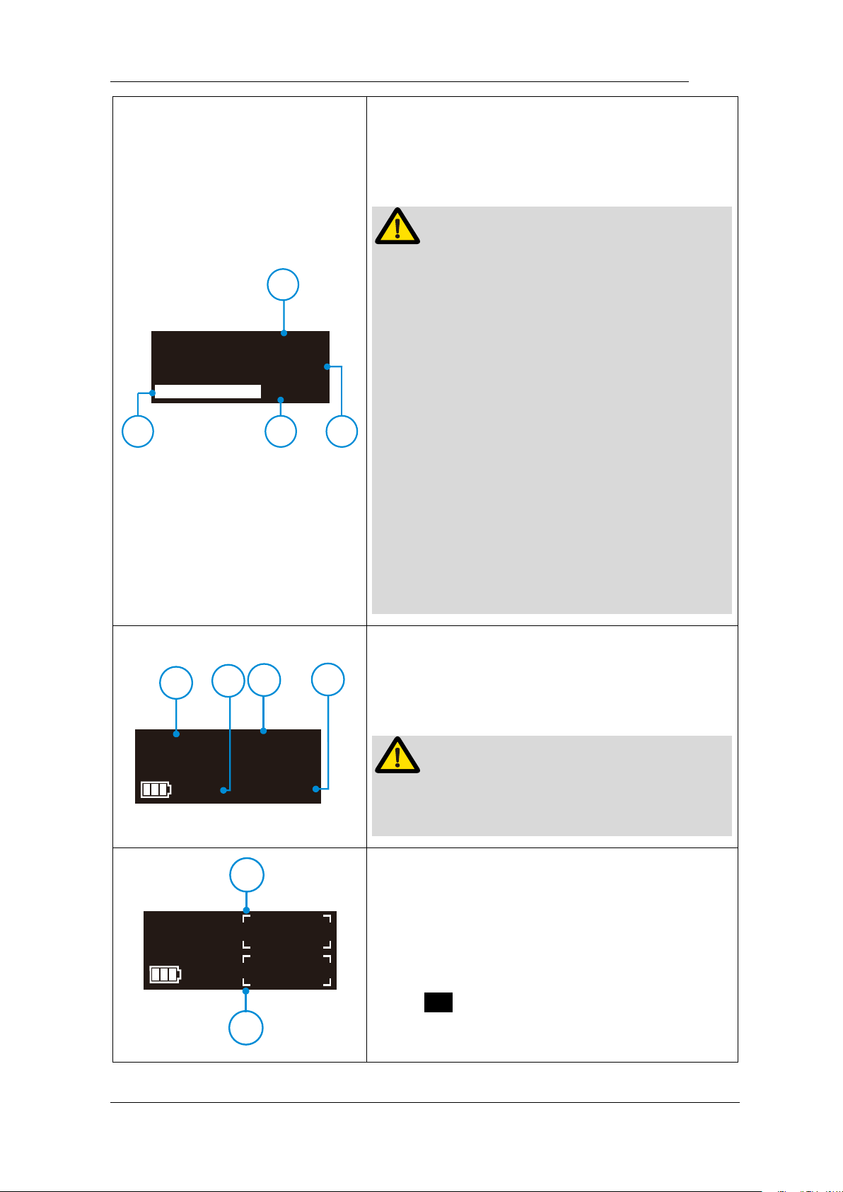
For convenience, we preset some common file
system.
Long press S to entry preset program
during standby state, the interface will show as
left.
M1 (○,1) meanings the current memory mode,
you can replace it by preset program (○,
2
)
press < or > to change, then press ●
to confirm.
Page 29
Page 29 / 59
300 r pm
CW
Ncm
2.5
2
1 3
OneShape
OneFlare
2Shape
OneCurve
4
If you selecting “OneCurve” (○,1), the
operation mode (○,2), speed (○,3) and torque
limit (○,4) will change according to the file
system default setting.
NOTE
Protaper
○,
R
, GATES
○,
R
, Pro.Glider
○,
R
, and
Wave one
○,
R
is a registered trademark of
Dentsply.
Mtwo
○,
R
, Flex.Master
○,
R
, Reciproc
○,
R
and R-
Pilot
○,
R
is a registered trademark of VDW.
K3XF
○,
R
, TF
○,
R
is a registered trademark of
SybronEndo.
OneG
○,
R
, OneShape
○,
R
, OneFlare
○,
R
,
2Shape
○,
R
and OneCurve
○,
R
is a registered
trademark of Micro-Mega
XPendo.Shaper
○,
R
, XPendo.Finisher
○,
R
,
iRace
○,
R
, BT-Race
○,
R
and BioRace
○,
R
is a
registered trademark of FKG
OneCurve
300 rpm
Fwd
Ncm
2.5
1
3 4
2
And the memory mode (○,1) will change
according, also operation mode (○,2), speed
(○,3) and torque limit (○,4) will charge
according to the file system default setting.
NOTE
All of memory mode (from M1-M10) can be
replaced with same mothed.
OneCurve
350
rpm
Fwd
Ncm
3.0
1
2
The parameters of “OneCurve” can also be
changed make it different from default setting,
and there will be 4 corners around the
parameter (○,1)(○,
2
).
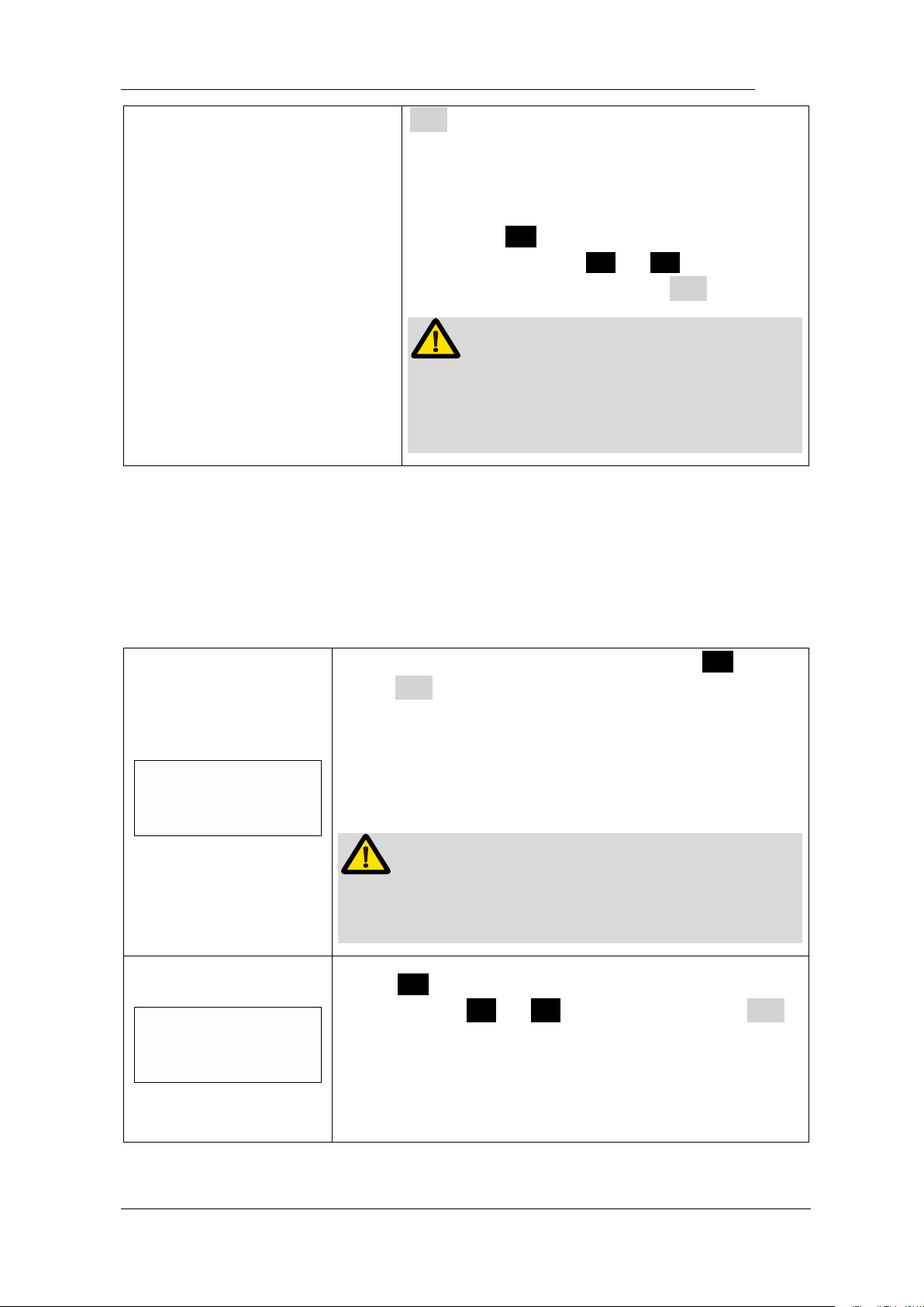
If want to change back to default setting, long
press S to entry preset program during
standby state, select “OneCurve” and press
Page 30
Page 30 / 59
● to confirm, the default setting will be
recalled, and the 4 corners around will
disappear.
If want to change back to M1 (or M2-M10),
long press S to entry preset program during
standby state, press < or > to select M1
(or M2-M10) again, then press ● to confirm
WARNING
Changing the default setting is not
recommended only if you are very sure it can
be changed, otherwise has risk of file broken.
6.4 Advanced setting
Ver si ons
E.1.1.008
During power off state, holding down press S then
press ● to entry advanced setting, the version
number software will appear on the display screen.
E-connect S can update software very easy without
tools and software. Contact your distributor to update if
necessary.
NOTE
After updating, all of the setting parameters will be
covered.
Aut o Power Of f
10 Mi n
Press S again, the “Auto Power Off” time can be
change, press < or > to adjust, then press ●
to confirm.
The “Auto Power Off” time can be set from 3-15
minutes.
Page 31
Page 31 / 59
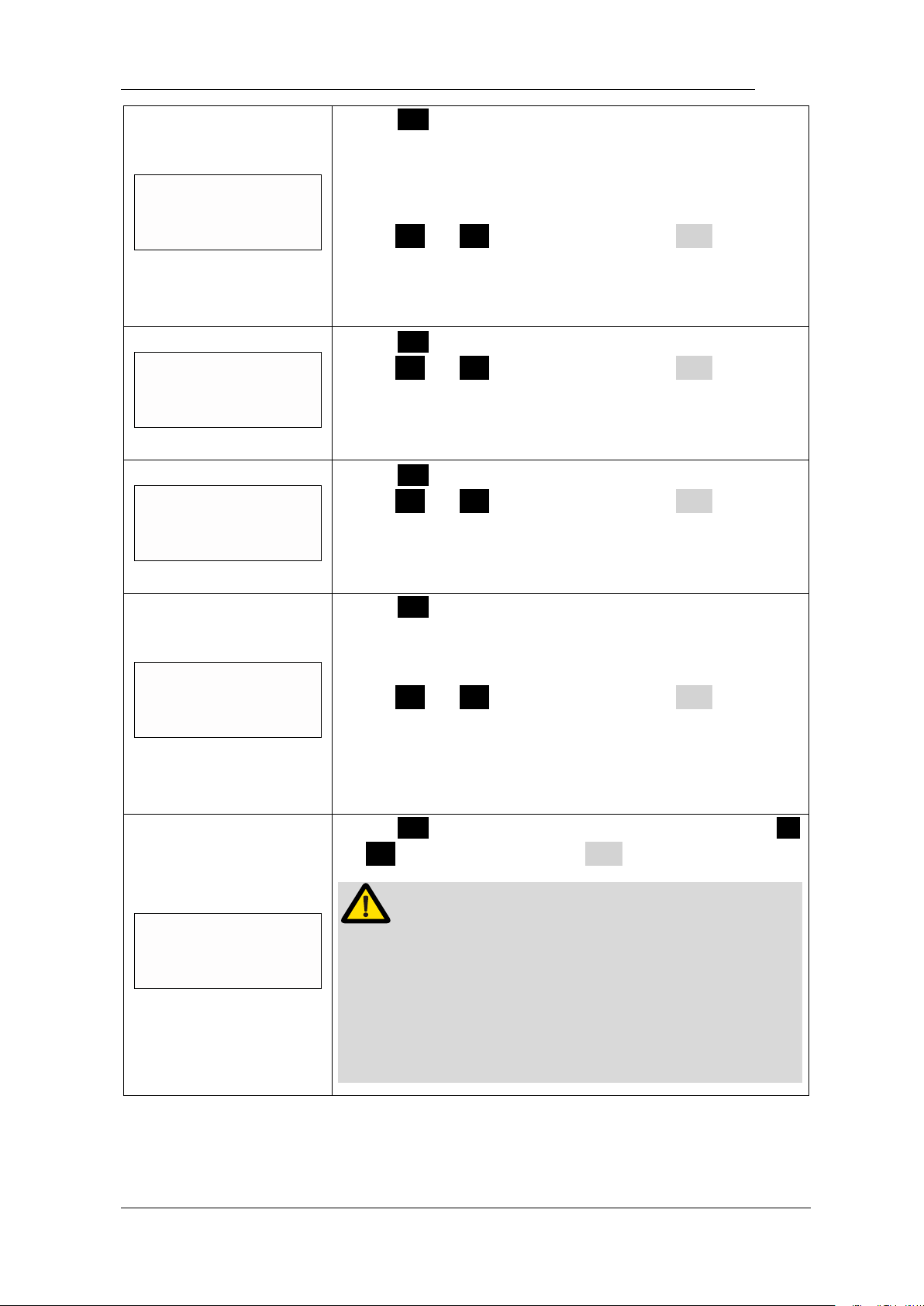
Auto Ret urn ti me
5 Sec
Press S again, the “Auto Return time” can be
change, it means when setting parameters just like
speed and torque, the system will back to standby
interface if there is no operation in 5 seconds.
press < or > to adjust, then press ● to
confirm.
The “Auto Return time” can be set from 3-15 seconds.
Beeper Vol ume
Vol . 2
Press S again, the “Beeper Volume” can be change,
press < or > to adjust, then press ● to
confirm.
The “Beeper Volume” can be set from 0-3.
Habi t hand
Right Hand
Press S again, the “Habit hand” can be change,
press < or > to adjust, then press ● to
confirm.
The right hand and the left hand can be set.
St art up memory
M1
Press S again, the “Start memory” can be change, it
means every time turn power on, which memory mode
will appear first.
press < or > to adjust, then press ● to
confirm.
M1 and Last (the memory mode number when you turn
power of ) can be set.
Cal i br at i on
OFF
Press S again, entry “Calibration” function, press <
or > to select “ON”, press ● to start calibration.
WARNING
Before calibrating, making sure the original contra
angle is installed, and do not install the file.
The torque will not correct if calibration without original
contra angle or any load on contra angle chuck, and
has risk of file broken.
Page 32
Page 32 / 59
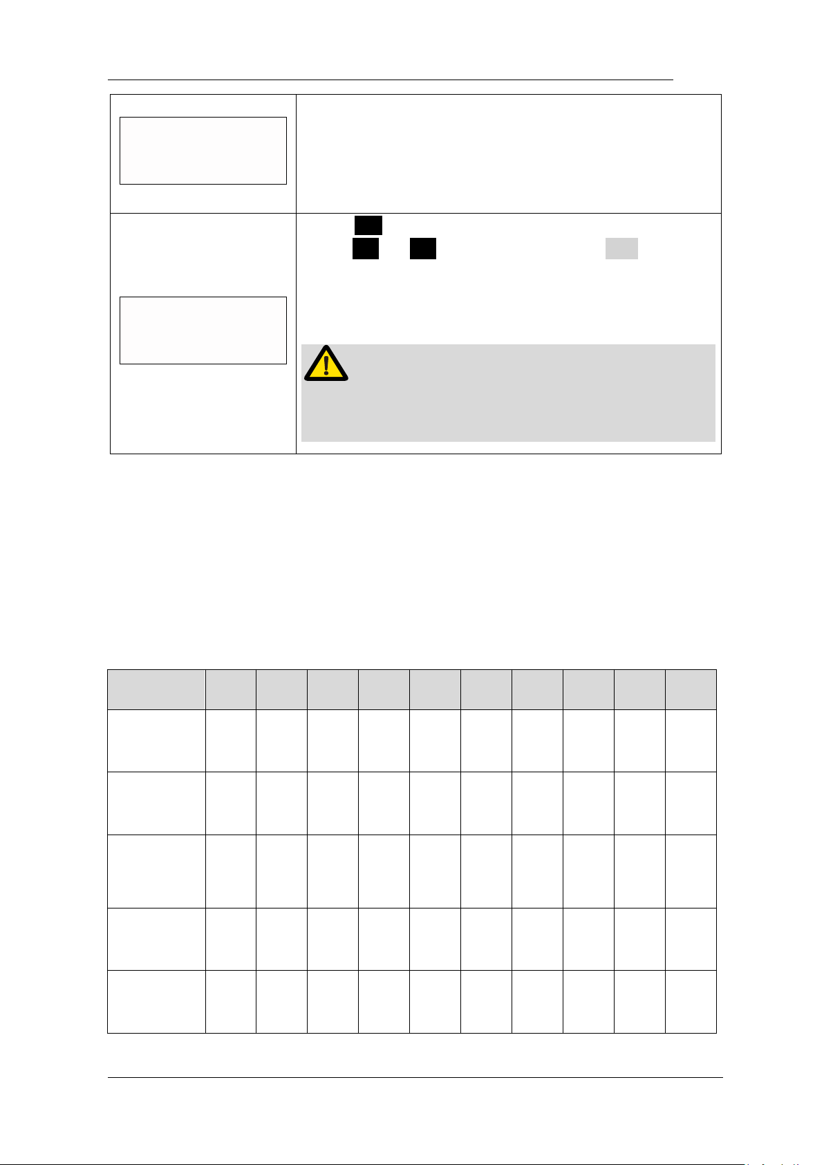
Calibration
1000 r pm
The motor speed will increase from 120 to 1000 rpm.
When the speed up to 1000 rpm, the calibration
successful and automatic power off.
R settingsestore
OFF
Press S again, entry “Restore setting” function,
press < or > to select “ON”, press ● to start
recovering, all the parameters be set by operator will be
recovered by default factory setting (See chapter 6.5
Parameter logic).
NOTE
After restore setting, all the parameters will be covered,
record what you need before this operation.
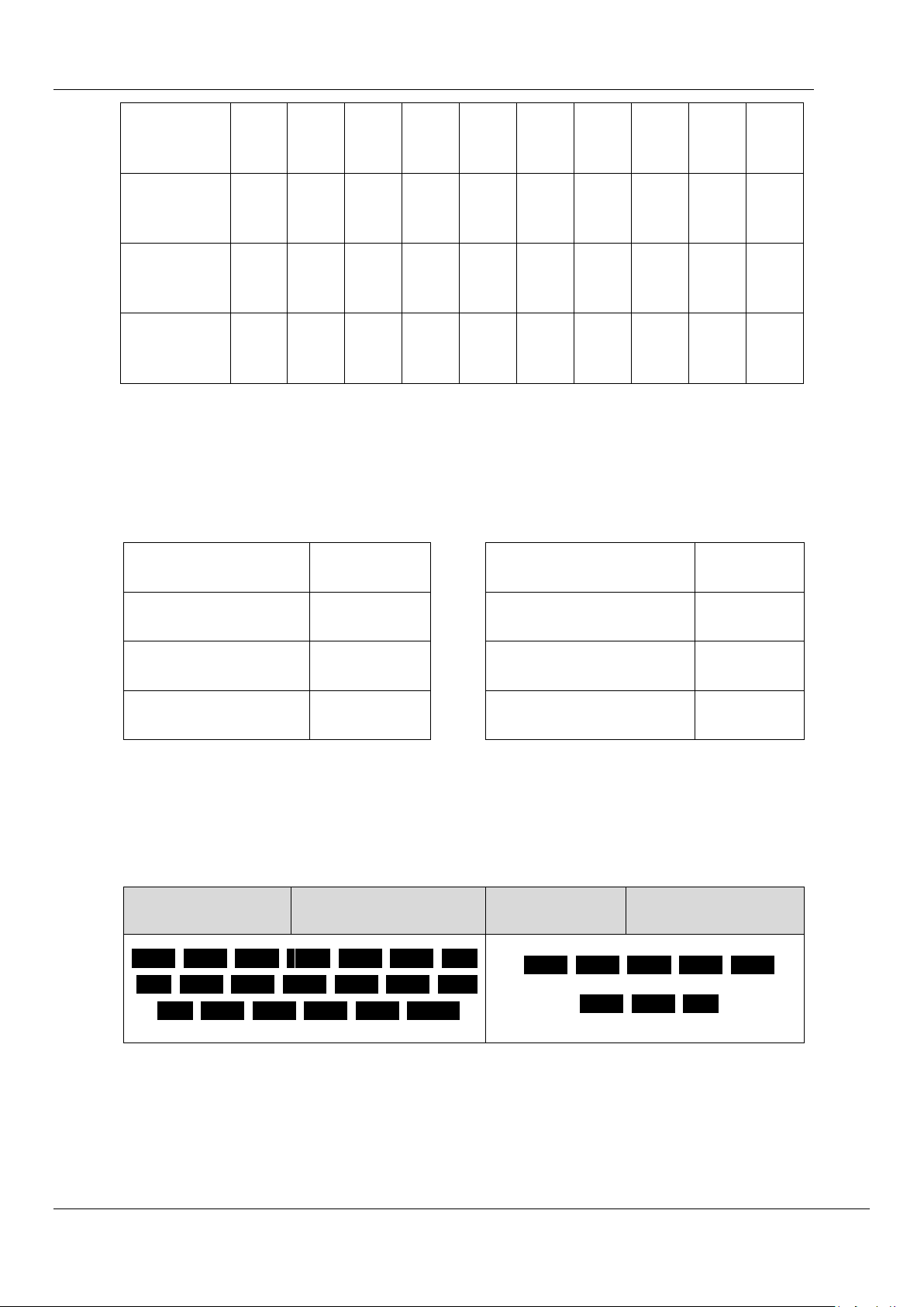
6.5 Parameter logic
The default memory settings are listed below, the setting can be changed as
needed.
Function
M1
M2
M3
M4
M5
M6
M7
M8
M9
M10
Operation
Mode
FWD
FWD
REC
REC
ATC
ATC
REV
REV
FWD
FWD
Speed
(rpm)
300
400
350
450
450
300
350
500
800
1000
Torque Limit
(N·cm)
3.0
2.0
N/A
N/A
1.5
1.5
2.5
2.0
1.5
1.0
Auto
Start
ON
ON
ON
ON
ON
ON
ON
ON
ON
ON
Auto
Stop
OFF
OFF
OFF
OFF
OFF
OFF
OFF
OFF
OFF
OFF
Page 33
Page 33 / 59
Apical
Action
REV
REV
REV
REV
REV
REV
REV
REV
REV
REV
Reference
point
02
02
02
02
02
02
02
02
02
02
FWD
Angle
N/A
N/A
30
40
370
210
N/A
N/A
N/A
N/A
REV
Angle
N/A
N/A
150
160
50
50
N/A
N/A
N/A
N/A
The default advanced settings are listed below, the setting can be changed as
needed.
Auto Power off
10Min
Startup memory
M1
Auto Return time
5Sec Language
English
Beeper Volume
2 Calibration
OFF
Habit hand
Right hand
Restore settings
OFF
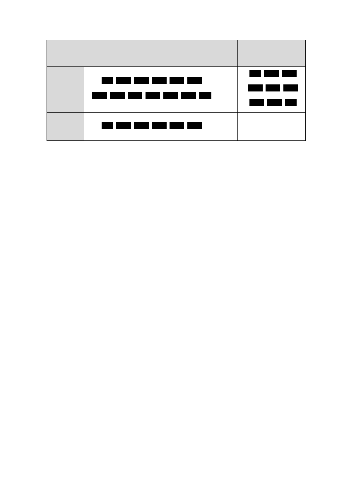
The speeds (rpm) in different operation mode are not the same, details are
listed below.
Fwd
Rev
REC
ATC
120 150 200 250 280 300 350
400 450 500 550 600 650 700
750 800 850 900 950 1000
150 200 250 300 350
400 450 500
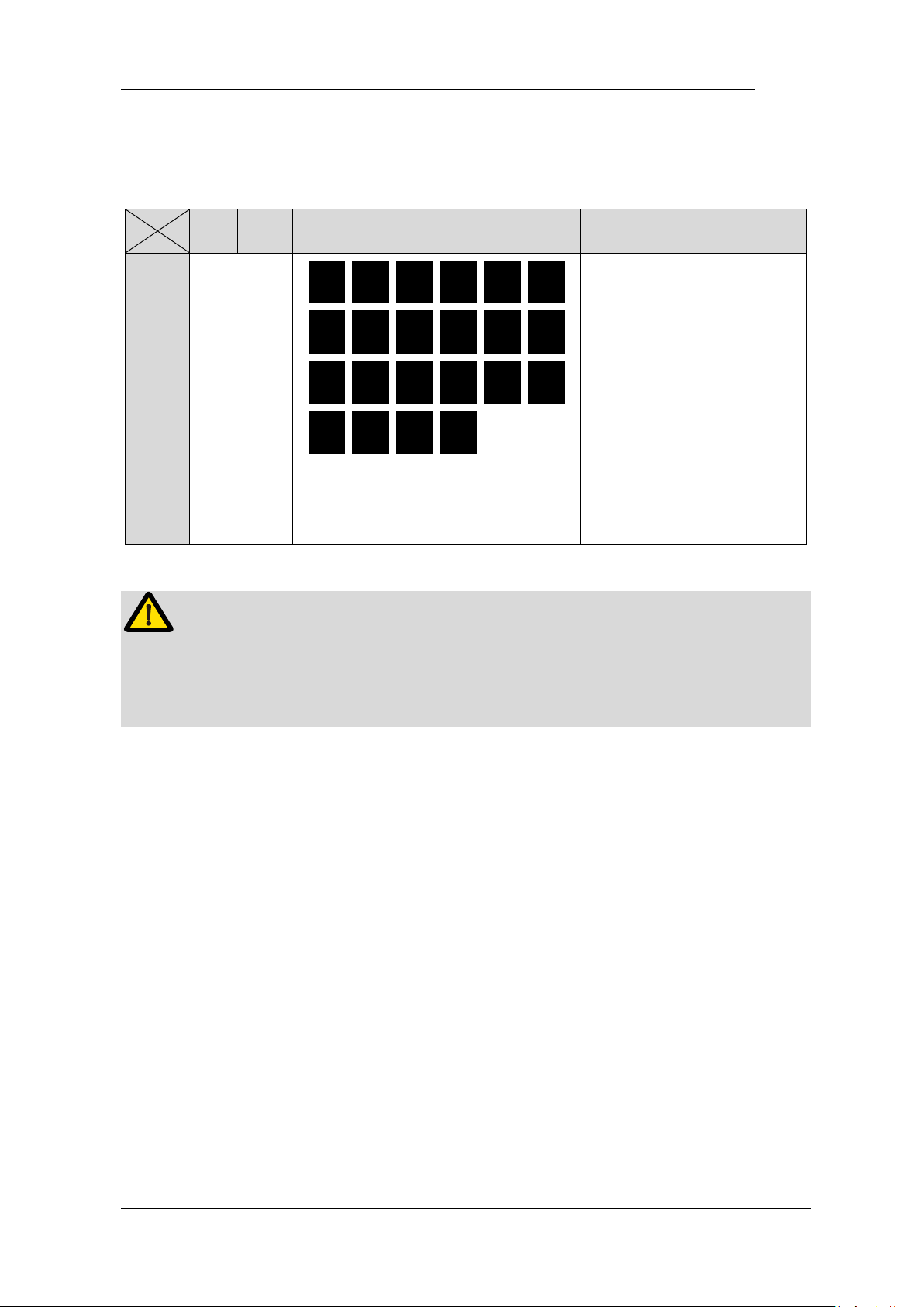
The torques (N·cm) in different operation mode are not the same, and even in
the same operation mode, when the speed changing, the possible torque is
difference, details are listed below.
Page 34
Page 34 / 59
Speed
(rpm)
Fwd
Rev
REC
ATC
120-700
0.5 0.8 1.0 1.5 1.8 2.0
2.2 2.5 3.0 3.2 3.5 4.0 R.L
N/A
0.5 0.8 1.0
1.5 1.8 2.0
2.2 2.5 3.0
700-1000
0.5 0.8 1.0 1.5 1.8 2.0
N/A
N/A
Page 35
Page 35 / 59
The FWD Angle (degrees) and REV Angle (degrees) in different operation
mode are not the same, details are listed below.
Fwd
Rev
REC
ATC
FWD
Angle
N/A
30
40
50
60
70
80
90
100
120
150
160
180
200
230
250
260
280
300
320
340
360
370
The same with the front
table
REV
Angle
N/A
The same with the front table
The same with the front
table
NOTE
The sum of FWD Angle and REV Angle must be greater than 120°, the motor
system has closed the angle not needed. For example: if you set FWD Angle 30°,
the REV Angle must be setting greater than 90°.
Page 36
Page 36 / 59
7.Operation
7.1 Charge
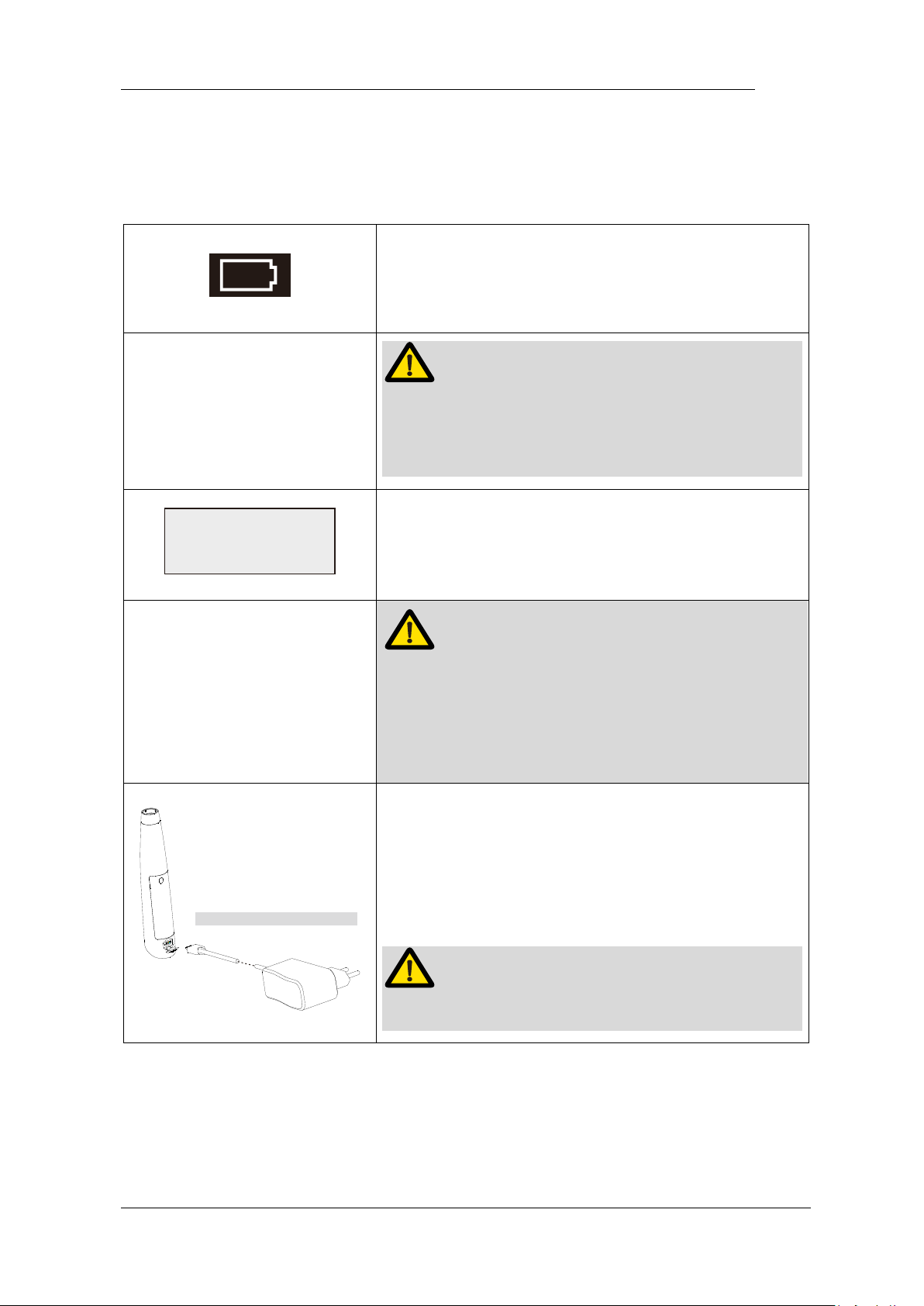
Displays the present remaining amount of the
battery.
Less than 15% remains, please charge.
NOTE
If the power if less than 15%, must be recharged
within 30 days, otherwise the battery will be
damaged.
LowPower
Please Charge
If continue to use, the torque and speed will low
than the setting value, and low power warming will
appear on screen, and the device will stop work.
NOTE
The remaining amount of battery mark indicates a
voltage. When a load is applied to the motor
handpiece, the remaining amount of battery mark
appears to become lower.
Alternative charging method
Charge without charge base also available, using
adapter connect to handpiece directly, the charge
state will show on the screen.
Charge with charge base is recommended (See
chapter 4.4 Connecting charge base).
NOTE
Only the original adapter could be used.
Page 37
Page 37 / 59
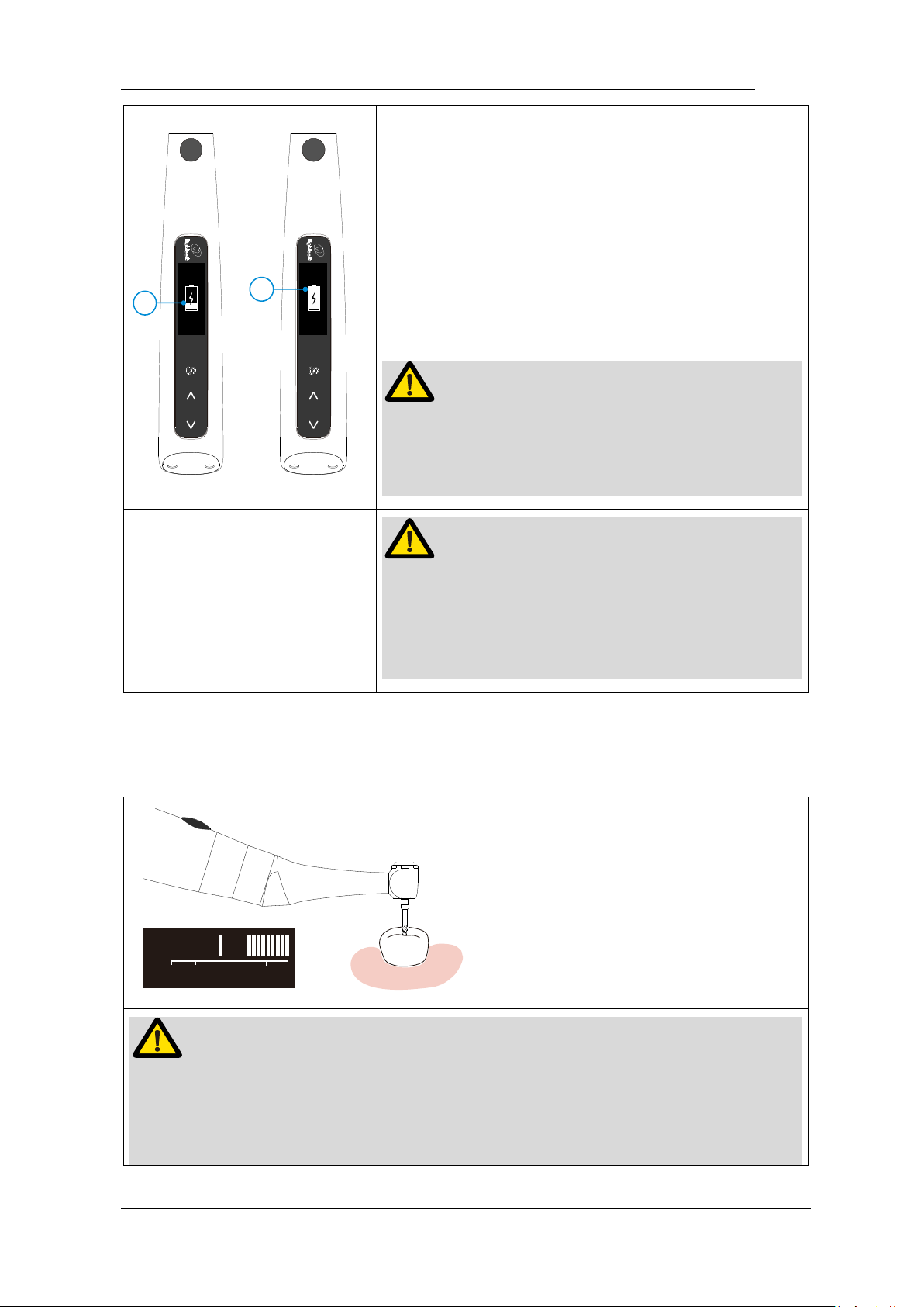
1
2
Charging indication appears on the screen, and
flashes slowly (○,1), when battery is fully charged
or in a state near full charge, the flash will stop and
show like picture (○,
2
).
Fully charged will take about 4 hours, depending
on residual battery power and battery state.
It can be recharged 300-500 times, depending on
the operating conditions of the device.
NOTE
When changing, other function will forcibly stop,
take from charge base, press main switch, the last
function will recall.
WARNING
Do not change the battery, only trained technician
or distributor can change the battery, the electronic
parts will be damaged if use a wrong battery or
install with a wrong way.
7.2 Motor operation
rpm
N.cm
3
5
0
5
4
3
2
1
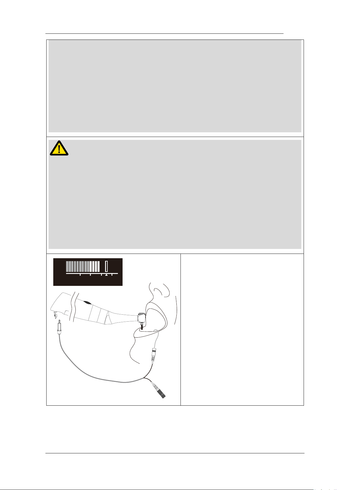
When using as a stand-alone motor,
the torque bar will show on the screen
(more information about torque
bar, please see chapter 5.2 Screen
display).
WARNING
Use the E-connect S outside the oral cavity to make sure that the device is
functioning properly.
Change file on time to avoid file separation within the canal. File may separate
Page 38
Page 38 / 59
because of cyclic / torsional fatigue.
Heavy force / hand pressure on endo motor while using may even cause file
separation.
Do not press the button to release the files while the motor is running, otherwise
the file may pop out and even hurt the patient.
Electromagnetic noise in surroundings environment may interfere with the device
operation, do not rely on device’s automatic control completely, always pay
attention to the feedback from display.
NOTE
If there is any abnormal functioning, stop using the device and report to company.
The file separates more easily at high speeds, please follow the manufacturer’s
recommendations of the speed and check the settings of the Endo motor before
use.
Do not use the files are except nickel-titanium or stainless steel.
Gloves and a rubber dam are compulsory during treatment.
Do not forget to remove the file from the Contra-angle after its use.
3
1
0
5
2
A
P
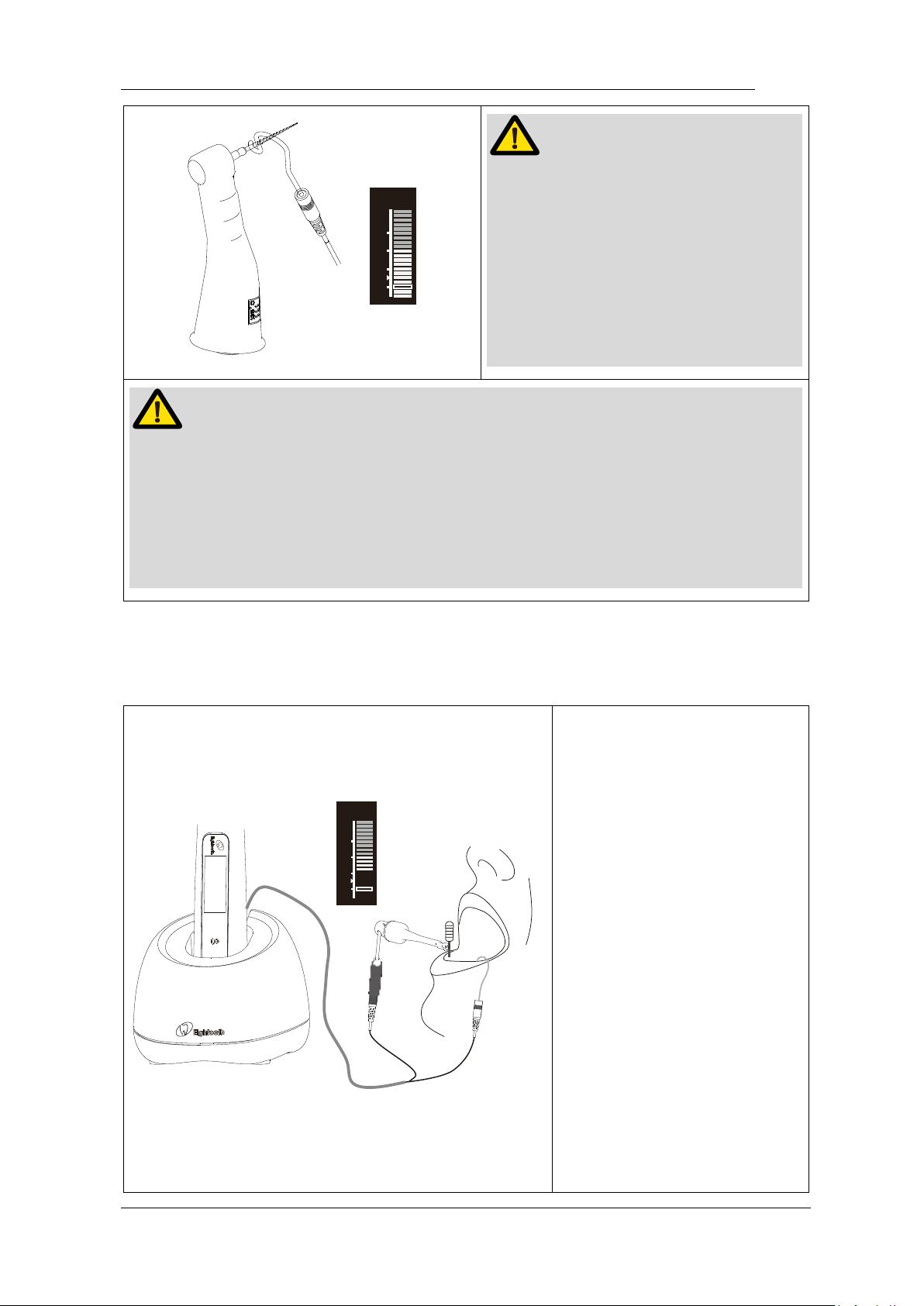
When using motor combine apex
function, the measure wire must be
connecting with motor by USB socket,
and white slot connects with lip by lip
hook, keep the black slot idle.
The reference point bar will show on
the screen (more information about
reference point bar, please see
chapter 5.2 Screen display).
Page 39
Page 39 / 59
3
1
-
2
2
A
P
NOTE
We strongly recommend check the
function every time before use.
Touch the lip hook with the file in the
contra angle and check that all the
bars on the meter on the screen light
up, and the motor should be reversed
continuously.
NOTE
The will not be able to perform a precise measurement for every time, especially
in cases of abnormal or unusual morphology of the root canal. The user need
coordinate with x-ray to check the results of the measurement.
If the meter does not move when you enter the file, it is possible that the unit is not
working normally, therefore, stop using.
7.3 Apex operation and not suitable condition
3
1
0
5
2
A
P
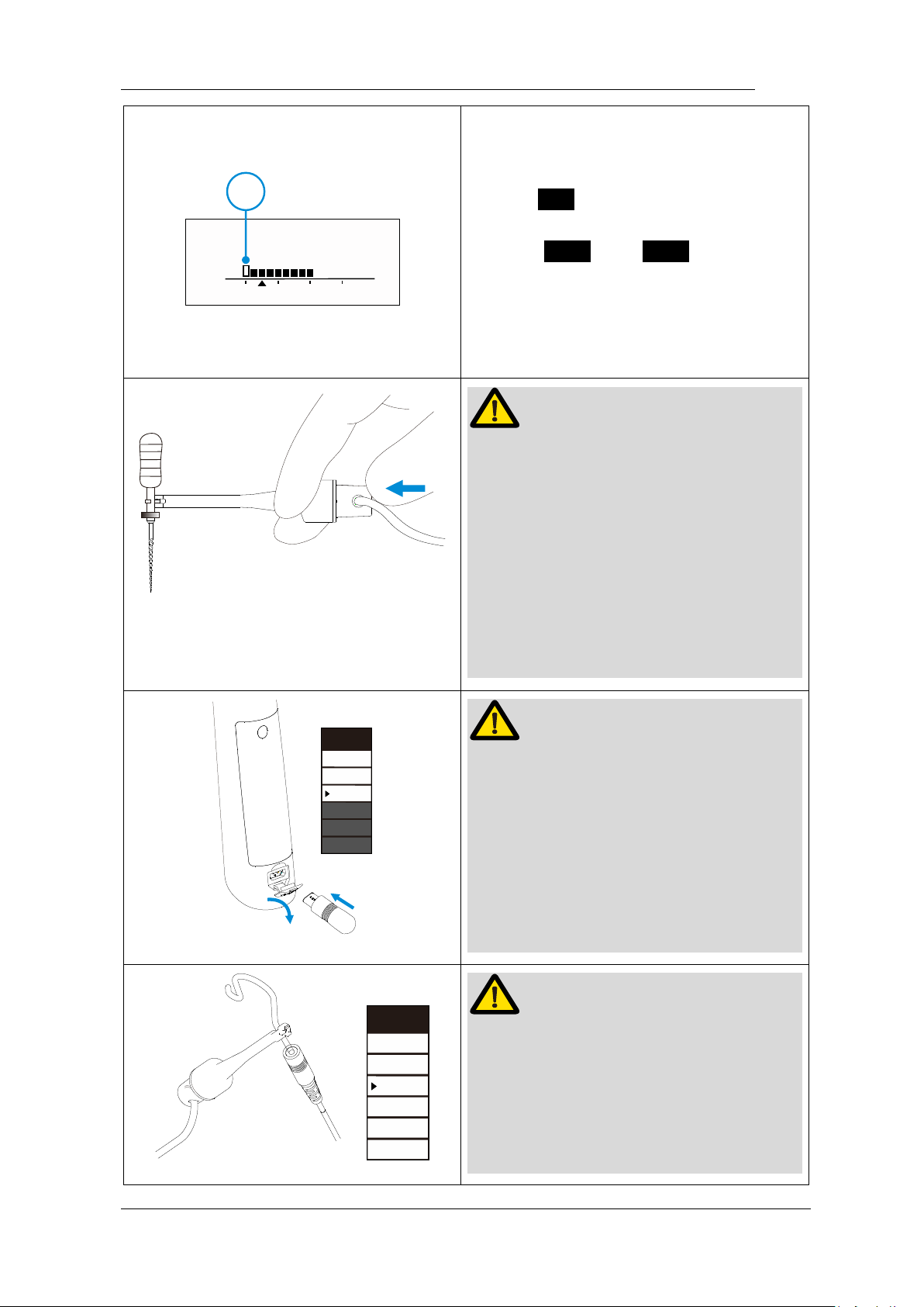
When using as a stand-alone
apex locator. We suggest put
the handpiece on the charge
base to get better visual
angle.
the measure wire must be
connecting with motor by
USB socket, white slot
connects with lip by lip hook,
and black slot connect with
file clip.
the canal length indicator bar
will show on the screen
(more information about
canal length indicator bar,
please see chapter 5.2
Screen display).
Page 40
Page 40 / 59
Ref erencepoi nt
AP
1
32
1
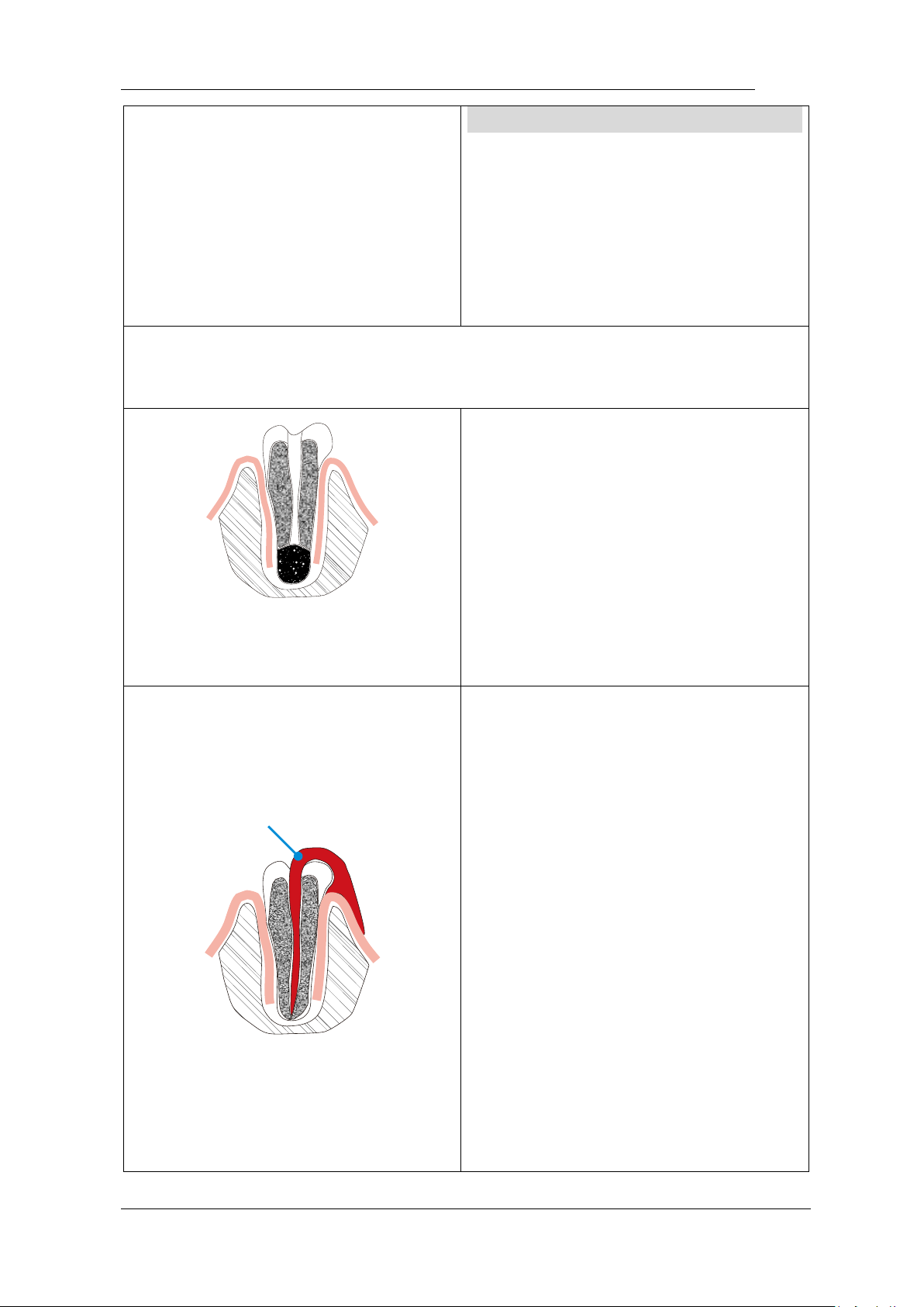
The reference point can be adjusting
when use stand-alone apex function.
Press S to active reference point
interface during M0 standby state,
Press < or > to change
reference point by change the flash bar
( ○,1 ), a continuous beeping with
appear when reach the reference point.
NOTE
The file clip must hold the file correctly.
Push the button of file clip in the direction
shown by the arrow, clip the holder onto
the metal upper part of the file and then
release the button.
The file clip must be nearly vertical with
file handle, otherwise will damage the tip
of the file holder.
m m
0.5
0
3
0
2
0
1
0
0
-
1
0
4
NOTE
We recommend using Apex Tester to
check the accuracy of apex locator every
time before use.
Insert the Apex Tester into handpiece
USB socket during M0 mode, check the
highlight number must between 01-03
(0.3mm-0.8mm on the top)
OVE
R
0
3
0
2
0
1
0
0
-
1
0
4
NOTE
We recommend check the connection of
apex locator every time before use.
Touch the lip hook with metal part of file
clip, check all the bars on the meter on
the screen light up, and “over” flash on
Page 41
Page 41 / 59
the top.
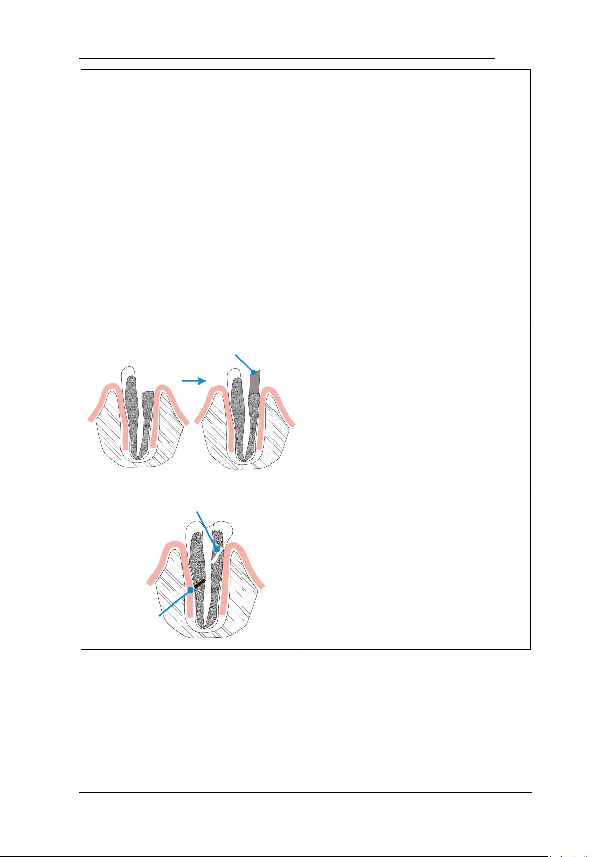
Unsuitable situation of root canals for Electric Measurement
Cannot obtain precise measurements if the root canal conditions as below
Root canal with a large apical
foramen
The root canal cannot be accurately
measured because of the lesion or
incomplete development of the apical
foramen. The results may show that the
length measured is shorter than the
actual one.
Clean
Root canal blood overflow from the
opening
If blood spills from the root opening and
contacts the gums, it will cause leakage
of electricity, which cannot be accurately
measured. Wait for the bleeding to stop
completely. Clean the root canal and the
opening, completely empty the root
canal blood, and then measure it.
The root canal uses a chemical
solution to flow out from the opening
If a chemical solution flows out of the
root canal, it is impossible to get an
accurate measurement.
It is important to remove the overflow
Page 42
Page 42 / 59
from the opening.
Build-up (e.g. cement)
Broken crown
If the crown is broken, a segment of the
gingival tissue enters the lumen, and the
contact between the gingival tissue and
the root file causes electrical leakage,
which cannot be accurately measured.
In this case, the appropriate material
should be used to isolate the gingival
tissue.
Branch
Crack
The crack tooth Leakage through
branch of the root canal
Broken teeth can cause electrical
leakage and cannot be accurately
measured.
Branch tubes can also cause leakage.
Page 43
Page 43 / 59
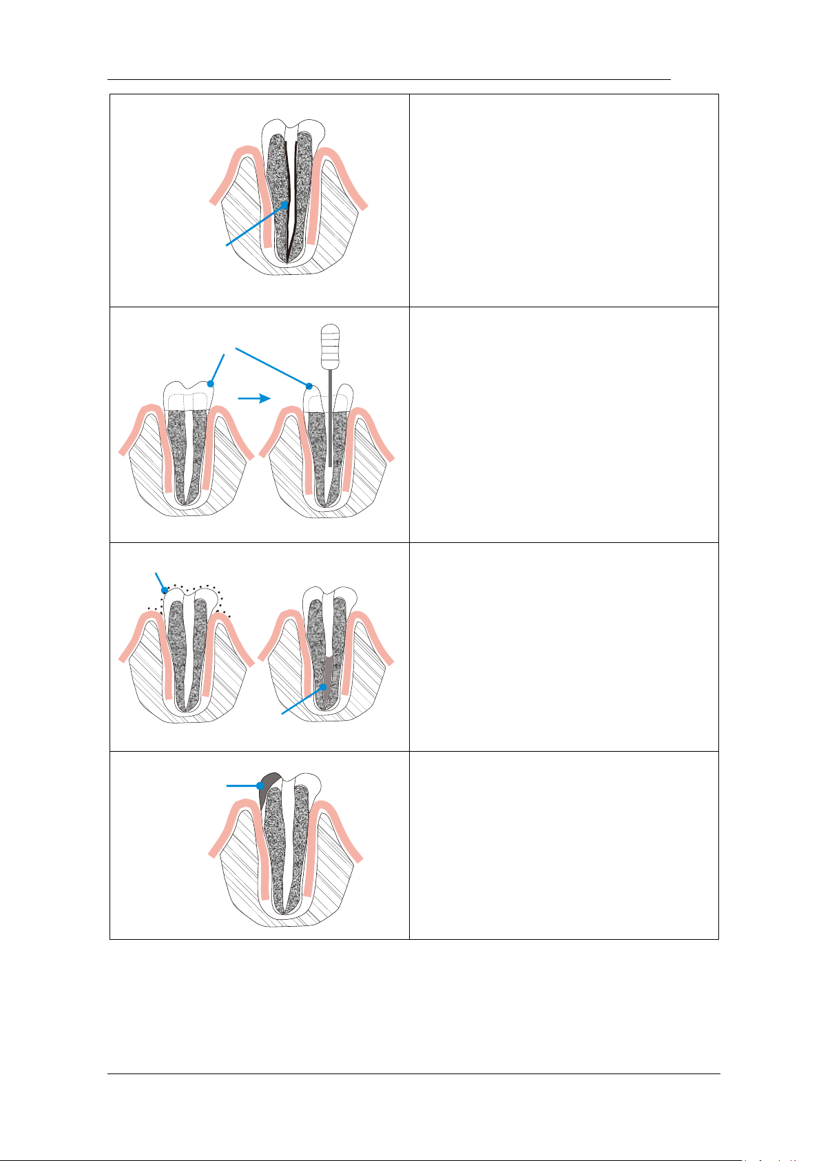
Gutta-percha
Retreatment canal which was filled
with gutta-percha
The gutta-percha must be completely
removed to eliminate its insulation, then
pass a small file all the way through the
apical foramen and then put a little saline
in the canal, but do not let it overflow the
canal opening.
Crown
Crown or metal prosthesis that
touches gingival tissue
Accurate measurement cannot be
obtained if the file touches a mental
prosthesis that is touching gingival
tissue. In this case, widen the opening at
the top of the crown so that the file will
not touch the mental prosthesis before
taking a measurement.
Debris
Pulp
Cutting debris on tooth Pulp inside
canal
Remove all cutting debris on the tooth.
Remove all the pulp inside the canal.
Otherwise an accurate measurement
cannot be obtained.
Caries
touches
gums
Caries touching the gums
In this case, electrical leakage through
the caries infected area to the gums are
impossible to obtain an accurate
measurement.
Page 44
Page 44 / 59
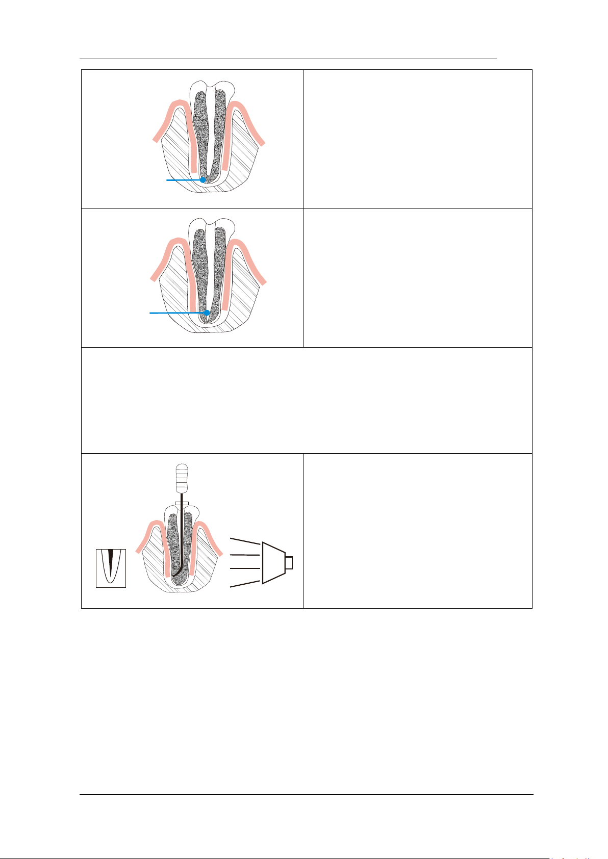
Blocked
Blocked canal
The meter will not run if the canal is
blocked. Opening the canal all the way
to the apical construction to measure it.
Too dry
Extremely dry canal
If the canal is extremely dry, the meter
may not work until it is quite close to
the apex. In this case, try to moisten
the canal with oxydol or saline.
Difference measuring result between Apex locator reading and Radiography
Sometimes the reading of the apex locator reading does not correspond to the Xray image. this does not mean inaccurate of apex locator or X-ray, depending on
the angle of the X-ray beam, the root tip may not be displayed correctly. The
position of the root tip seems to differ from its true position.
X-ray tube
X-ray photo
The X-ray photo shows that the actual
apex of the root canal is not the same as
the anatomic end. In fact, the apical
foramen is located at the coronal end. in
this case, X-ray may indicate that the file
needle has not reached the apical
foramen, even if it has actually reached
the apical foramen.
Page 45
Page 45 / 59
8.Maintenance
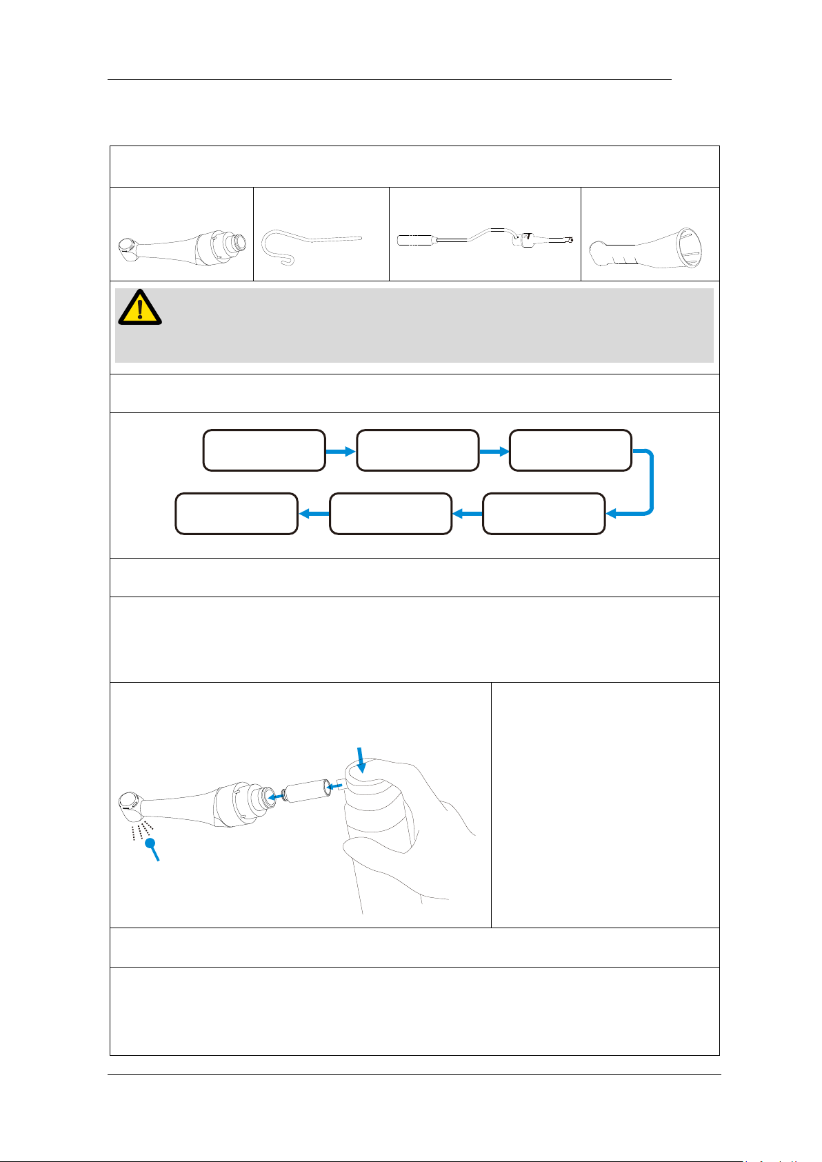
Autoclavable Components
Contra Angle
Lip Hook
File clip
Insulating Sleeve
WARNING
Only the components above can be autoclaved.
Autoclavable Procedure
Cleaning
Disinfection Lubrication
Packing
Sterilization
Storage
Cleaning: Clean the components with running water with a soft cloth.
Disinfection: Wipe the components with a piece of gauze that has been
dampened with Ethanol for Disinfection (Ethanol 70 to 80 vol%) and wrung out
thoroughly.
Lubrication: Only the contra angle needs to be
lubricated
Black oil
Before autoclaving, the
contra angle must be
lubricated.
Attaching the spray nozzle to
oil can and contra angle,
press the oil can button more
than 3 seconds, till all the
black oil flow out from the
head of the contra angle.
Packing: Pack the components in“Sterilization pouches”.
Sterilization: Steam sterilization at 134°C at least 4 minutes or
steam sterilization at 121°C at least 35 minutes.
Page 46
Page 46 / 59
Minimum drying time after sterilization: 10 minutes.
Storage: Keep the components in sterilization packaging in a dry and clean
environment.
WARNING
Comply with your national guidelines, standards and requirements for cleaning,
disinfection and sterilization.
Be careful to avoid cross contamination when performing maintenance.
Must be autoclaved after use for each.
Do not lubricate the motor handpiece.
Page 47
Page 47 / 59
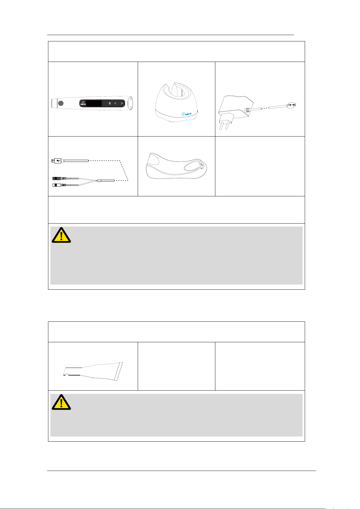
Disinfection components
Motor Handpiece
Charge Base
Adapter
Measuring Wire
Handpiece Base
Wipe the components with a piece of gauze that has been dampened with Ethanol for
Disinfection (Ethanol 70 to 80 vol%) and wrung out thoroughly.
NOTE
Do not use anything except Ethanol for Disinfection (Ethanol 70 to 80 vol%).
Do not use too much ethanol as it’s going into machine and damage the
components inside.
Single-use component
Disposable Sleeve
NOTE
Single-use handle sleeve must be disposed of and changed after every
treatment. In the event of non-compliance, the contamination risk increases.
Page 48
Page 48 / 59
9.Error Warning
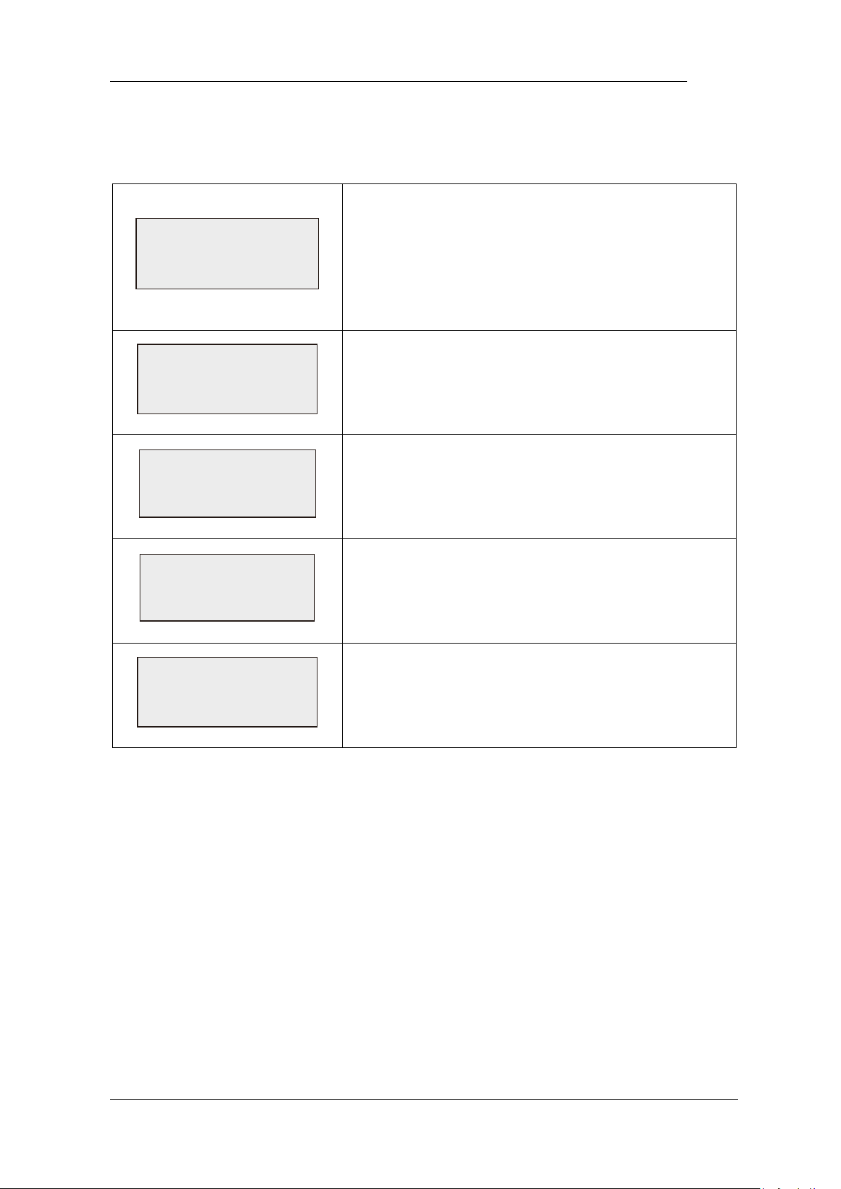
Overload
Restart Motor
When setting the torque limit as R.L or during
reverse processing, the Overload warning may
appear on the screen, it means a large load
happened greater than the motor force.
Press the Main switch to restart motor.
Overheat
See user manual
The temperature of motor is higher than
expectation, turn the power off and waiting more
than 5 minutes to let it cold down.
HWFault
See user manual
Hardware of the handpiece broken, contact your
distributor.
Moto rFaul t
See user manual
Motor of the handpiece broken, contact your
distributor.
LowPower
Please Charge
The power is very low, charge it immediately
Page 49

Page 49 / 59
10.Troubleshooting
When trouble is found, check the following points before contacting your distributor.
If none of these are applicable or the trouble is not remedied even after action has
been taken, the product may have failed. Contact your distributor.
Problem
Cause
Solution
Ref.
chap
The power is
not turned on.
The battery is flat.
Charge the battery.
7.1
Press the main switch too
short time.
Press the main switch
more than 0.5 seconds.
5.1
The power LED
on charge base
does not light.
Using a wrong adapter.
Use the original
adapter.
4.4
The adapter is not connected.
Check the connection.
4.4
The plug of the adapter is not
inserted into the outlet.
Check the connection.
/
There is no electricity in the
outlet.
Check the connection.
/
No charge
indicator flash
on handpiece
screen
Put the handpiece into the
charge base in the wrong
direction.
Check the direction.
4.4
Charge pin of charge base
unable to rebound.
Remove debris which
between move part and
base of the charge pin.
/
Contactors are dirty.
Cleaning the surface of
contactors.
/
The charge base broken.
using adapter connect to
handpiece directly, and
Contact your distributor.
/
Handpiece
The handpiece broken.
Check if there is a sound
of beep or motor, and
/
Page 50

Page 50 / 59
screen does not
appear
Contact your distributor.
The motor
doesn’t rotate.
M0 mode is stand-alone apex
locator function.
Changing to M1-M10.
6.1
The contra-angle is clogged
Clean or replace the
contra-angle.
/
Motor is protected by system
or broken.
Check the error warning.
9
Motor does not
run when the file
is inserted in the
canal.
The measure wire connecting
not properly.
Check the connection.
4.3
The lip hook not properly
hooked in the corner of the
patient’s mouth.
Check the connection.
7.2
7.3
The Auto start function is OFF
Turn the auto start
function ON if
necessary.
6.2
The motor Can’t
stop.
The Auto stop function is OFF.
Press main switch to
stop it, setting Auto stop
function ON if
necessary.
6.2
There is a short circuit inside
the motor handpiece or the
motor handpiece cord.
Press “S” button to stop
the motor and contact
your distributor.
/
Motor
spontaneously
starts running in
reverse.
Up to setting torque limit.
Check the torque limit is
enough or not.
6.2
Apical action setting to
Reverse
Change setting if it’s not
expected.
6.2
Setting to REV mode.
Change setting if it’s not
expected.
6.2
Motor does not
reverse.
R.L mode is set.
Change setting if it’s not
expected.
6.2
Torque reverse setting might
be too high.
Change setting if it’s not
expected.
6.2
Page 51

Page 51 / 59
Apical action setting Stop or
OFF.
Change setting if it’s not
expected.
6.2
Motor speed
changes
spontaneously.
Apical action setting Slow
Down.
Change setting if it’s not
expected.
6.2
Motor alternates
between
forward and
reverse rotation.
Operation mode setting to
REC or ATC.
Change setting if it’s not
expected.
6.2
No sound.
Beep volume set to 0.
Set beep volume to 1, 2
or 3.
6.4
Beep sound an
alarm even
though the
instrument is not
being used.
The motor is set to REV or
R.L mode.
If it is the expected
mode, ignore the alarm.
6.2
Canal
measurement is
unstable.
Complex root canal
environment.
Check situation of root
canals.
7.3
Cannot make a
measurement.
Measure wire, lip hook or file
clip connecting not properly.
Check the connection.
7.2
7.3
Lack electrical conductivity
between the shank and the
file.
Use a file that has
conductivity.
/
Unsuitable situation of root
canals.
Check the root canal
environment.
7.3
Page 52

Page 52 / 59
11.Technical Data
Manufacturer
Changzhou eighteeth medical technology Co.,Ltd
Model
E-connect S
Dimensions
21.5cm x 17.5cm x 9cm (Outer box)
Weight
800g
Contra-angle
Contra-angle compatible with rotary and reciprocating
instruments, equipped with a 2.35 mm shaft conforming
to ISO 1797-1:2011, Type 1
Power supply
Lithium ion battery: 3.7V, 1500mAh
Charger power supply
AC 100-240 V
Frequency
50/60Hz
Charger nominal
power input
5.5VA
Torque range
0.5Ncm – 4Ncm
Speed range
120-1000 rpm
Electrical safety class
Class II
Applied part
BF
Ambient conditions
Use: in enclosed spaces
Ambient temperature: 15°C / 35 °C
Relative humidity: <80%; non-condensing at 0°
Operating altitude < 2000 m above sea level
Transport and storage
conditions
Ambient temperature: -20 °C / +50 °C
Relative humidity: 20% - 80 %,
non-condensing at > 40 °C
Atmospheric pressure: 50 kPa - 106 kPa
Page 53

Page 53 / 59
12.EMC Tables
Guidance and manufacturer’s declaration – electromagnetic emissions
The E-connect S is intended for use in the electromagnetic environment specified below.
The customer or the user of the E-connect S should assure that it is used in such an
environment.
Emissions test
Compliance
Electromagnetic environment - guidance
RF emissions CISPR
11
Group 1
The E-connect S uses RF energy only for its
internal function. Therefore, its RF emissions are
very low and are not likely to cause any
interference in nearby electronic equipment.
RF emissions CISPR
11
Class B
The E-connect S is suitable for use in all
establishments, including domestic
establishments and those directly connected to
the public low-voltage power supply network
that supplies buildings used for domestic
purposes.
Harmonic emissions
IEC61000-3-2
Not
applicable
Voltage
fluctuations/flicker
emissions
IEC 61000-3-3
Not
applicable
Guidance and manufacturer’s declaration – electromagnetic immunity
The E-connect S is intended for use in the electromagnetic environment specified below.
The customer or the user of the E-connect S should assure that it is used in such an
environment.
Immunity test
IEC 60601 test
level
Compliance level
Electromagnetic
environment - guidance
Page 54

Page 54 / 59
Electrostatic
discharge (ESD)
IEC 61000-4-2
+6 kV contact
+8 kV air
+2, 4, 6 kV
contact
+2, 4, 8 kV air
Floors should be wood,
concrete or ceramic tile. If
floors are covered with
synthetic material, the
relative humidity should be at
least 30 %.
Electrical fast
transients/bursts
IEC 61000-4-4
+2 kV for power
supply lines
+1 kV for
input/output lines
Not applicable
Not applicable
The test is applicable since
the EUT
does not have AC/DC power
ports and signal/
interconnecting cable
longer than 3m.
Surge
IEC 61000-4-5
+1 kV line(s) to
line(s)
+2 kV line(s) to
earth
Not applicable
Not applicable
The test is not applicable
since the EUT does not have
AC power port.
Voltage dips,
short
interruptions and
voltage
variations on
power supply
lines
IEC 61000-4-11
<5% UT
(>95% dip in UT)
for 0.5 cycle
40% UT
(60% dip in UT )
for 5 cycles
70% UT
(30% dip in UT )
for 25 cycles
<5% UT
(>95% dip in UT)
for 5 sec
Not applicable
Not applicable
Not applicable
Not applicable
The test is not applicable
since the EUT does not have
AC power port.
Page 55

Page 55 / 59
Power frequency
(50/60 Hz)
magnetic field
IEC 61000-4-8
3 A/m
3 A/m
Power frequency magnetic
field should be at levels
characteristic of a typical
location in a typical
commercial or hospital
environment.
Note UT is the a.c. mains voltage prior to application of the test level.
Guidance and manufacturer’s declaration – electromagnetic immunity
The E-connect S is intended for use in the electromagnetic environment specified below.
The customer or the user of the E-connect S should assure that it is used in such an
environment.
Immuni
ty test
IEC
60601 test
level
Comp
liance
level
Electromagnetic environment - guidance
Conduct
ed RF
3 Vrms
150 kHz
to 80 MHz
3 V
Portable and mobile RF communications equipment
should be used no closer to any part of the E-connect S,
including cables, than the recommended separation
distance calculated from the equation applicable to the
frequency of the transmitter.
Recommended separation distance
1.2dP= 1.2dP=
80 MHz~800 MHz
2.3dP=
800 MHz~2.5 GHz
IEC
61000-46
V/m
Radiated
RF
Page 56
Page 56 / 59
IEC
61000-43
3 V/m
80 MHz to
2.5 GHz
3.5
V/m
Where P is the maximum output power rating of the
transmitter in watts (W) according to the transmitter
manufacturer and d is the recommended separation
distance in meters (m). Field strengths from fixed RF
transmitters, as determined by an electromagnetic site
survey, ashould be less than the compliance level in each
frequency range. b
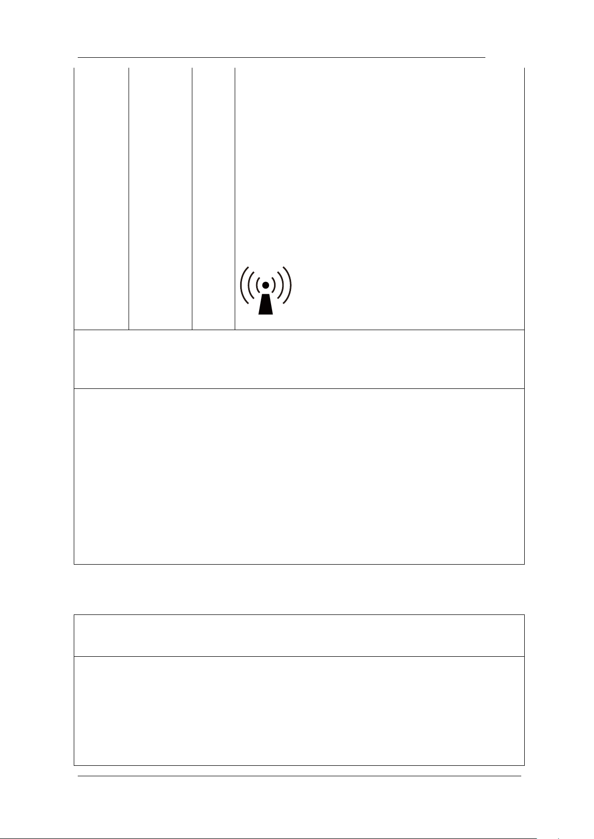
Interference may occur in the vicinity of equipment
marked with the following symbol:
NOTE 1: At 80 MHz and 800 MHz, the higher frequency range applies.
NOTE 2: These guidelines may not apply in all situations. Electromagnetic propagation is
affected be absorption and reflection from structures, objects and people.
a Field strengths from fixed transmitters, such as base stations for ratio (cellular/cordless)
telephones and land mobile radios, amateur radio, AM and FM radio broadcast and TV
broadcast cannot be predicated theoretically with accuracy. To assess the electromagnetic
environment due to fixed RF transmitters, an electromagnetic site survey should be
considered. If the measured field strength in
the location in which the E-connect S is used exceeds the applicable RF compliance level
above, the E-connect S should be observed to verify normal operation. If abnormal
performance is observed, additional measures may be necessary, such as reorienting of
relocating the E-connect S.
b Over the frequency range 150 kHz to 80MHz, field strengths should be less than 3 V/m.
Recommended separation distances between portable and mobile RF communications
equipment and the E-connect S.
The E-connect S is intended for use in an electromagnetic environment in which radiated
RF disturbances are controlled. The customer or the user of the E-connect S can help
prevent electromagnetic interference by maintaining a minimum distance between portable
and mobile RF communications equipment (transmitters) and the E-connect S as
recommended below, according to the maximum output power of the communications
equipment.
Page 57

Page 57 / 59
Rated maximum
output power of
transmitter
W
Separation distance according to frequency of transmitter
m
150 kHz to 80 MHz
1.2dP=
80 MHz to 800 MHz
1.2dP=
800 MHz to 2.5 GHz
2.3dP=
0.01
0.12
0.12
0.23
0.1
0.38
0.38
0.73
1
1.2
1.2
2.3
10
3.8
3.8
7.3
100
12
12
23
For transmitters rated at a maximum output power not listed above, the recommended
separation distance d in meters (m) can be estimated using the equation applicable to the
frequency of the transmitter, where P is the maximum output power rating of the
transmitter in watts (W) according to the transmitter manufacturer.
NOTE 1: At 80 MHz and 800 MHz, the separation distance for the higher frequency range
applies.
NOTE 2: These guidelines may not apply in all situations. Electromagnetic propagation is
affected by absorption and reflection from structures, objects and people.
Page 58

Page 58 / 59
13.Statement
All rights of modifying the product are reserved to the manufacturer without further
notice. The pictures are only for reference. The final interpretation rights belong to
CHANGZHOU EIGHTEETH MEDICAL TECHNOLOGY CO., LTD. The industrial
design, inner structure, etc, have claimed for several patents by EIGHTEETH, any
copy or fake product must take legal responsibilities.
Page 59

Page 59 / 59
Changzhou Eighteeth Medcial Technology Co., Ltd
Add: NO.99 Qingyang Road Xuejia Town, Xinbei District Changzhou City, 213125,
Jiangsu Province, China
Tel: +86-0519-85962691
Fax: +86-0519-85962691
Email: [email protected]
Web: www.eighteeth.com
Berwin Industy Ltd.
Tel: +44 0208 492 6388
Fax: +44 0208 492 0196
Add: 419, Harborne Road, Edgbaston, Birmingham, B15 3LB.
William Jefferson
[email protected]
Version: A0
BKY-CE-60-1007
Issued: Mar. 26, 2018
Copyright © Eighteeth Ltd, 2016.
All rights reserved.
 Loading...