

Page 1
1
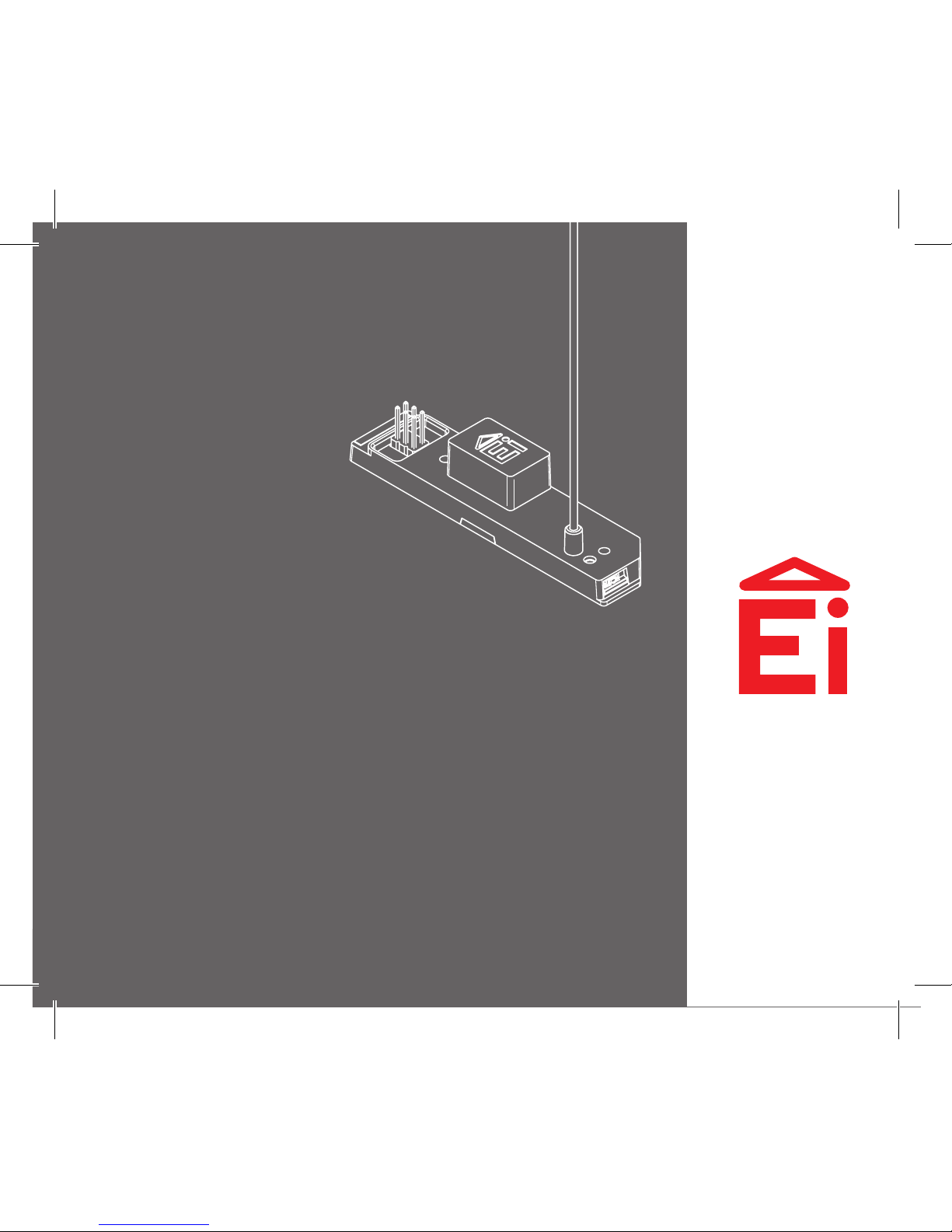
SmartLINK Module Ei3000MRF
for Mains Powered Multi-Sensor Fire / Smoke / Heat /
CO Alarms - Ei3000 Series
Instruction Manual
Read and retain carefully for as long as the product is being used. It contains vital
information on the operation and installation of your Alarm. The leaflet should be
regarded as part of the product.
If you are just installing the unit, the leaflet MUST be given to the householder. The
leaflet is to be given to any subsequent user.
Page 2

2
Page 3

3
1. Introduction 4
2. Installation and House Coding 6
3. System Installations 13
4. Additional Features 18
5. Troubleshooting and Indicator summary tables 22
6. Testing the System 29
7. Interconnected CO Alarms and Smoke Alarms 32
8. SmartLINK Troubleshooting 34
9. Technical Specifications 36
10. Guarantee 38
11. Limitations of Radio Communications 40
Contents
Page 4

4
1
Introduction
Page 5

5
The Ei3000MRF SmartLINK Module is the next generation RF module from Ei Electronics
designed to fit in the Ei3000 series, Easi-fit mains powered Alarms.
The primary function of the Ei3000MRF is to wirelessly interconnect all Ei Electronics Alarms
in a system by means of an RF signal i.e. when one Alarm senses a fire event, the Ei3000MRF
module fitted to that Alarm will transmit an RF signal that will activate the sounders in all
other RF Alarms in the system.
Other features include:
• Remote House coding, to reduce installation time for Alarm additions to existing sites.
• Data Extraction, to collect important information on the Alarm status, including
activations, tests, CO levels, faults etc.
• Monitoring (buddy system) where the strongest RF signal paths are selected between a
pair of devices as a means to monitor the RF connection.
• Live Monitoring, via the Ei1000G Gateway and the proprietary Cloud portal, to track
Alarm activations, tampering, faults etc. and provide for planned maintenance.
The Ei3000MRF module is simply plugged into the rear of the base of an Ei3000 series Alarm.
RF communication via this module eliminates the need to install long interconnect wires
between all the Alarms on different floors in different rooms. The Ei3000MRF is powered
from the Alarm it is connected to.
The module also has “multiple repeater” transmission – this provides multiple signal paths
to create a robust RF ‘mesh’ system and also increase the RF range.
Page 6

6
2
Installation and
House Coding
Page 7
7
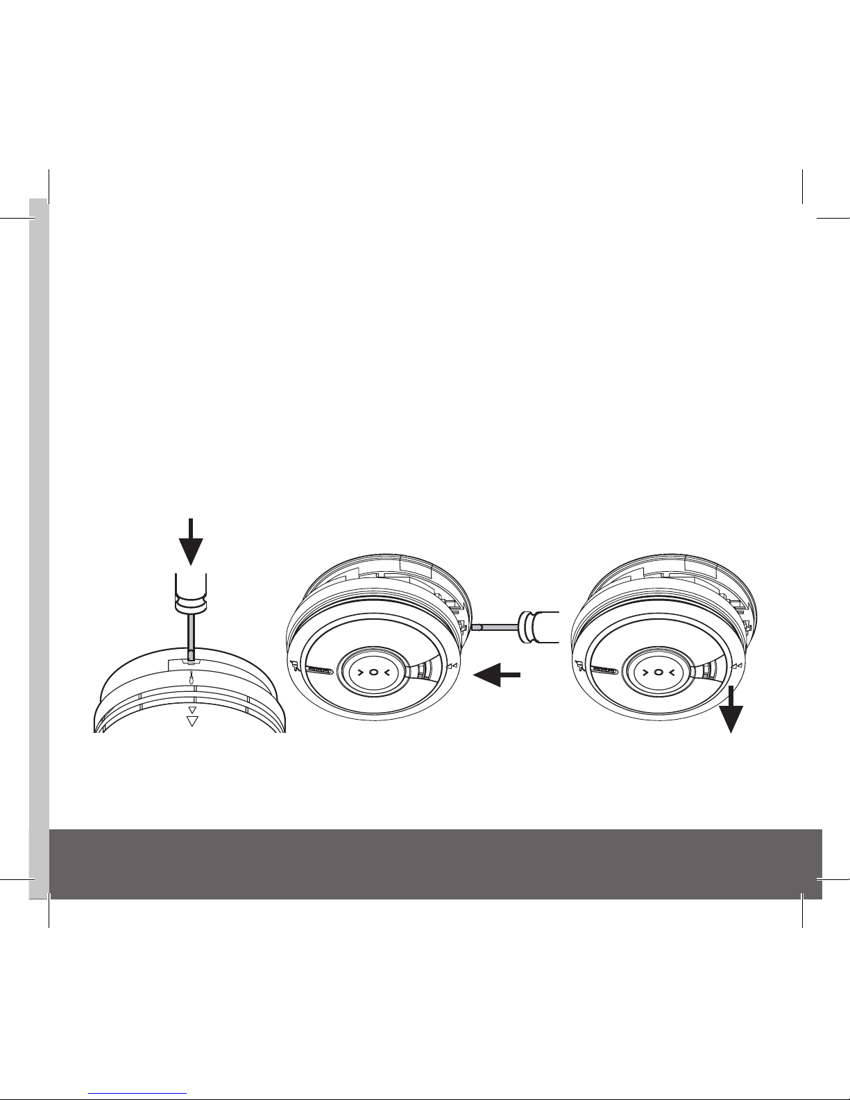
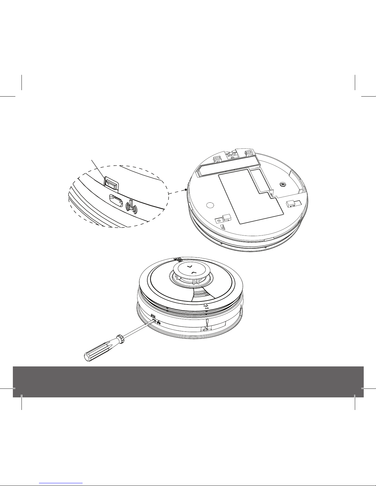
N.B Disconnect Mains Before Alarm Head Removal
After disconnecting the mains power supply, it is now safe to remove the Alarm from its
base. Using a screwdriver, insert into the removal slot on the side of the Alarm.
Push the lower half of the Alarm away away from the screwdriver, in the direction of the
arrow on the cover (see Figure 1 below).
CAUTION: The existing hard-wired interconnection may need to be disconnected at this
point (refer to the Installation section in the Alarm instruction manual). If a hard-wired
connection and an RF connection exist between the SAME two Alarms, a continuous Alarm
loop signal may occur.
Figure 1
Page 8
8
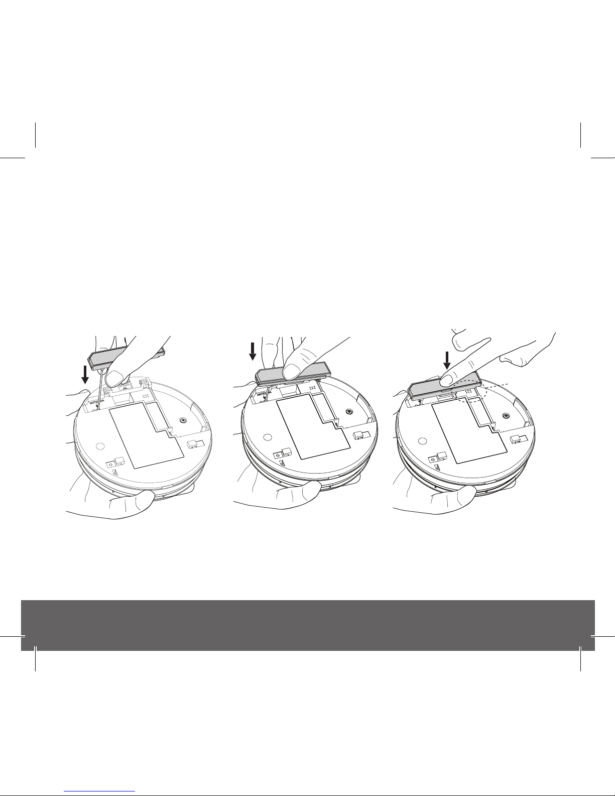
Fitting the Ei3000MRF Module
To fit the Ei3000MRF Module, first hold the flexible antenna and guide it into its designated
hole in the rear of the unit until about 2/3 of its length is inserted (Fig. 2a). Then, hold the
module housing (Fig. 2b) and plug it into the Alarm, being careful to align the pins and
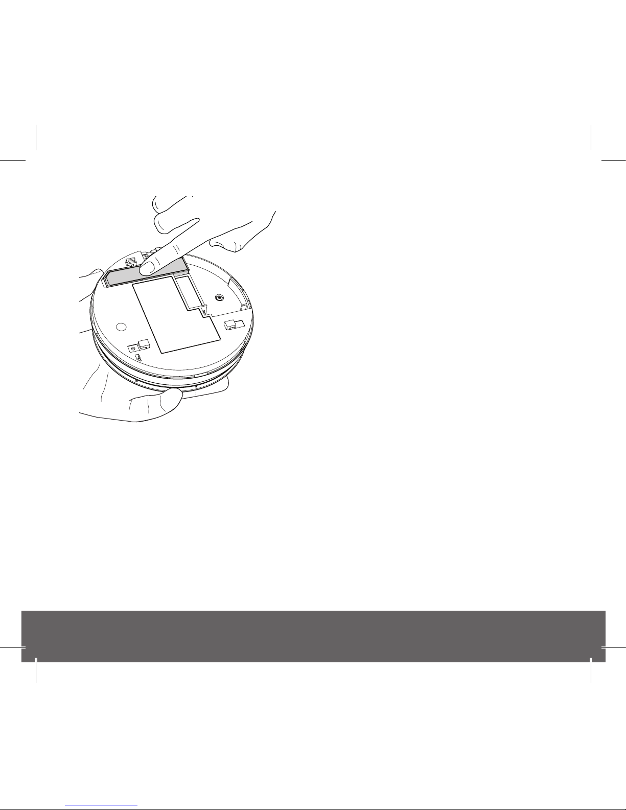
keeping them perpendicular to the base as the module is inserted (Fig. 2c). Ensure the
module is fully home, by checking that it is flush with the surrounding Alarm housing (Fig.
2d).
Pin
Alignment
Pin
Alignment
Pin
Alignment
Figure 2a Figure 2b Figure 2c
Page 9
9
House Coding the Unit
Re-connect the Alarm to the base. Switch back on
the mains power. Check for the green LED on the
Alarm cover. Power supply to the Ei3000MRF will
be confirmed by an initial flash of the red, blue and
green LED on the side of the unit (see Fig 3).
Using a screwdriver, press and hold the House Code
button on the side of the unit until the blue light
illuminates (see Fig 4).
Immediately release the button, the blue light will
flash rapidly and then stop.
The flashing will repeat every 5 seconds thereafter.
Repeat this procedure for all Alarms in the system.
Check to ensure all RF devices have been successfully House Coded. This can be done by
counting the number of blue flashes on each RF Module. The number of flashes should
correspond to the number of RF devices in the system. (i.e. 4 flashes if there are 4 devices
in the system). Note: If an Ei3028 Alarm is included in the system, there will be an extra
blue flash (this corresponds to the 2 independent sensors in the Alarm head). e.g with 4 RF
devices in a system, one of which is an Ei3028 you would expect 5 blue flashes during the
housecode process and so on.
Figure 2d
Page 10
10
N.B. We recommend, for ease of installation and RF communication, that up to 12
RF devices can be installed in any one RF coded system. Please contact us for further
advise if additional RF devices are required.
Figure 4
blue, red & green LED
Figure 3
Page 11

11
You can exit this mode by pressing the House Code button on one of the RF Alarms. Keep the
button pressed until the blue light comes on solid and then release.
The Alarm will now send a signal to all the other RF devices in the system to exit House Code.
Alternatively, the RF Alarms will automatically exit the House Code mode after 30 minutes.
To check the system, press the test button on any Alarm. After a few seconds all Alarms
should now sound. All Alarms in the system should be checked similarly.
Caution: Do not House Code another group (e.g. adjacent apartment) until the current
House Code has been completed.
Factory Reset
Sometimes in order to resolve an RF communication issue it may be necessary to reset
(factory reset) and House Code the system again. To do so, press and hold the House Code
button until you see a flashing blue light on the Alarm cover (approx. 7 seconds), release
immediately. Repeat this procedure on all Alarms.
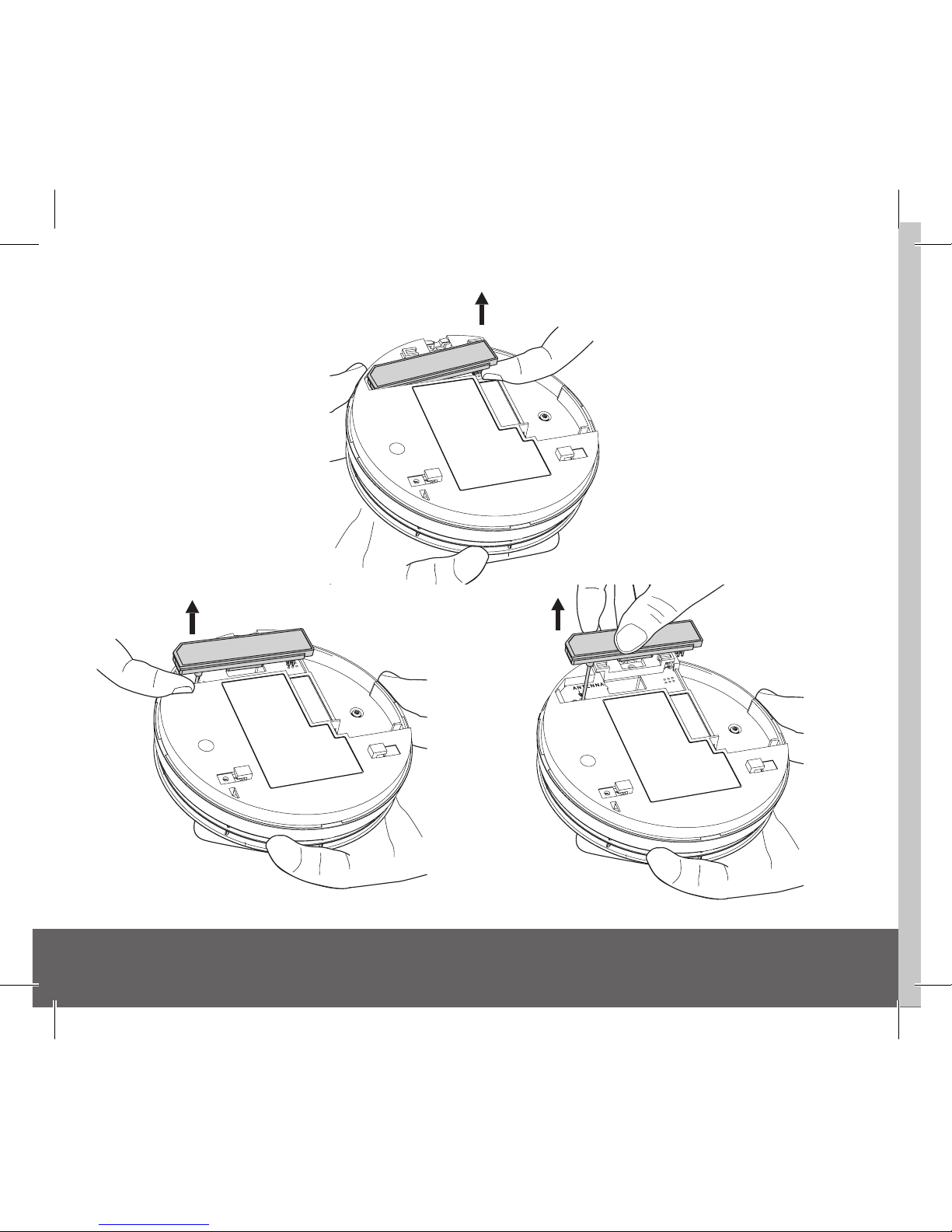
Removing the Ei3000MRF Module
If it is necessary to remove or replace an RF Module already fitted to an Alarm, it can be
taken out by firstly using your index finger to lift it by 5 to 6mm to release the connection
pins (Fig. 5a), repeat this process on the opposite end to release the antenna (Fig. 5b), after
which the module can be fully removed from the Alarm by lifting it away while keeping the
pins perpendicular to the Alarm (Fig. 5c).
Page 12
12
Pin
Alignment
Figure 5b
Figure 5c
Pin
Alignment
Figure 5a
Page 13

13
3
System
Installations
Page 14

14
Mixed Hardwired Interconnect and Wireless Interconnect (Hybrid) System
Ei3000 Series Alarms are also equipped to work in a hybrid system. A hybrid system is a
combination of hardwired interconnected and RF interconnected Alarms and devices. Hybrid
systems can be very flexible and allow extended fire and/or CO protection with minimum
installation disruption.
Hybrid Systems should be not be installed where specific alarm type (Fire or CO) indication
is critical - for example, if required to trigger switching equipment depending on the alarm
type detected. This is because the hardwire interconnect line does not communicate the
alarm type, whereas the RF interconnection does. Therefore, we recommend using RF only
interconnected Ei3000 series Alarms where specific alarm type indication is required.
Page 15

15
Hardwired
Carbon Monoxide
Alarm
Ei3018
The hardwired interconnected sections of a hybrid system should be
separated into CO only Alarms and Fire, Smoke and Heat Alarms, to ensure
that the alarm type is indicated correctly to the RF network during activation
Hardwired
Carbon Monoxide
Alarm
Ei3018
Hardwired
Carbon Monoxide
Alarm
Fire / CO
Alarm Interface
Ei3018
Ei414
Hardwired
Multi-Sensor
Fire Alarm
Hardwired
Optical
Smoke Alarm
Ei3024 Ei3016
Hardwired
Heat
Alarm
Ei3014
System
Alarm Controller
Ei450
Examples of various RF and Hardwired Systems
Page 16

16
Ei3018
The hardwired interconnected sections of a hybrid system should be
separated into CO only Alarms and Fire, Smoke and Heat Alarms, to ensure
that the alarm type is indicated correctly to the RF network during activation
Ei3018
Fire / CO
Alarm Interface
Ei3018
Ei414
Hardwired
Multi-Sensor
Fire Alarm
Hardwired
Optical
Smoke Alarm
Ei3024 Ei3016
Hardwired
Heat
Alarm
Ei3014
System
Alarm Controller
Ei450
RF Heat &
Carbon Monoxide
Alarm
Ei3028
The RF network can consist of a mixture of
Fire, Smoke, Heat and/or CO Alarm types
Fire / CO
Alarm Interface
Ei414
System
Alarm Controller
Ei450
RF
Multi-Sensor
Fire Alarm
Ei3024
RF
Carbon Monoxide
Alarm
Ei3016
RF
Optical
Smoke Alarm
RF
Heat
Alarm
Ei3014
Ei3018
Page 17

17
RF Heat &
Carbon Monoxide
Alarm
Ei3028
The RF network can consist of a mixture of
Fire, Smoke, Heat and/or CO Alarm types
Fire / CO
Alarm Interface
Ei414
System
Alarm Controller
Ei450
RF
Multi-Sensor
Fire Alarm
Ei3024
RF
Carbon Monoxide
Alarm
Ei3016
RF
Optical
Smoke Alarm
Hardwired
Multi-Sensor
Alarm
If an Ei3028 Heat and CO Alarm is required on a hardwired section,
it should be fitted to a Fire, Smoke and Heat only section, one per section
and that Ei3028 should also be the section‘s link to the RF network of the
hybrid system. This ensures that the RF Fire alarm message can be
transmitted if any device on the hardwire circuit is activated and the
RF CO Alarm message if the Ei3028 detects dangerous levels of CO
Fire / CO
Alarm Interface
Ei414
RF
Heat
Alarm
Ei3014
Ei3016
Hardwired
Optical
Smoke Alarm
Ei3024
Hardwired
Heat
Alarm
Ei3014
RF Heat &
Carbon Monoxide
Alarm
Ei3028
Ei3018
Page 18

18
4
Additional Features
Page 19

19
The Ei3000MRF SmartLINK Module provides a range of exciting new additional features:
1. Remote House Coding (if you want to add or replace an Alarm to an installed system)
If it is necessary to extend an RF system or you find that you want to add an extra Alarm to a
system you can now do so quite simply via the ‘Remote House Coding’ feature. Firstly using a
screwdriver, press and hold the House Code button of one of the previously installed Alarms
until you see all colours flashing - red, blue, green (typically takes about 8 seconds) and then
release. This Alarm will now send an RF message to all the previously installed (compatible)
devices to re-enter House Code mode. Similarly, install and put the new Alarm you wish to
add to the system into House Code mode (see “Installation and House Coding” section). As
before, allow sufficient time so that all Alarms are now house coded correctly (this can be
confirmed by counting the number of flashes on each Alarm). You can then exit House Code
mode manually or let it exit automatically after 30 minutes. (N.B. for this feature to work all
devices in the system must be SmartLINK or RadioLINK+).
2. Data Extraction
The Ei3000MRF SmartLINK Module allows for the extraction of certain information from an
Ei3000 Series Alarm, using an Ei Electronics download device. Once the system has been set
up, information can be accessed from within or outside a property (within RF range) if access
is an issue. This data is displayed as an event log and contains very useful information about
any recorded events in the history of the Alarm such as: Fire Events, Alarm Head removals,
Button Tests, CO levels and so on.
Event logs can be retrieved as many times as necessary and can be stored on your tablet,
Laptop or PC as a record of the status of the installation.
For more information on this feature please contact us directly.
Page 20

20
3. Monitoring (Buddy System)
The Ei3000MRF SmartLINK Module facilitates a simple monitoring or buddy system between
the Alarms. The system must first be successfully house coded. Then to enable Monitoring,
hold the House Code Button of one Alarm only until the green LED lights solid (typically
takes about 12 seconds) and then release. Each Alarm will “pair” with the strongest signal
than it has received during the house coding process. When successfully paired the LED will
flash blue-green. If the LED flashes blue-red, then pairing has failed. Try re-orientating the
Alarm heads or adding extra RF devices to improve the range. Then re-house code the system
and re-start the monitoring process again. To exit Monitoring mode, hold the House Code
Button until the green LED lights solid and then release. Alternatively, it will automatically
exit monitoring mode after 30 minutes.
Monitoring is now enabled in the network. If a paired Alarm then loses the signal from its
buddy, it will flash red-blue for 10 minutes (this can also be seen after a button test).
To disable monitoring, hold the House Code Button until the red LED lights solid and then release.
Note: A monitoring failure does not necessarily mean that the RF signal cannot be propagated
through the RF mesh network. Multiple path communication, via the mesh architecture,
ensures that the signal could be propagated through alternative signal paths to ensure the
required communication.
4. Smart Sound Pattern
When installed as part of a RF interconnected system of Ei3000 series CO and fire alarms
only, all devices will sound using the appropriate alarm sound pattern for the alarm
event detected. For example, if a CO detection triggered the alarm, then all Ei3000 RF
Page 21

21
interconnected devices will sound with the CO sound pattern. Similarly, if fire was detected,
then all devices will sound with the fire sound pattern. This feature is not available for
hardwired, mixed or hybrid installations.
5. Live Monitoring
The Ei3000MRF SmartLINK Module, together with the Ei1000G Gateway and the proprietary
Cloud portal, delivers a unique “live monitoring” of the installation.
For more information on this feature please contact us directly.
Page 22

22
5
Troubleshooting
and Indicator
summary tables
Page 23

23
Power Up
Blue LED Red LEDGreen LEDSound
Alarm
Head Removal
Mode
Standby
Normal Operation
= LED on solid
= LED flashing
Button Test
x 1
x 1
x 1
x 1 x 1 x 1
followed
by flash every 10 Sec
followed
by flash 1 minute later
Page 24

24
Power Up
Blue LED Red LEDGreen LEDSound
Alarm
Head Removal
Mode
Standby
= LED on solid
= LED flashing
Button Test
x 1
x 1
x 1
x 1 x 1 x 1
followed
by flash every 10 Sec
followed
by flash 1 minute later
House Code
enter
Press and release
on solid blue
Press and release
on solid blue
Button Action Blue LED Red LEDGreen LED
Mode
RF Mode
In house code
House code
exit
Press and release
on flashing blue
Factory reset
Press and release on
multi-colour flashing
Remote learn
entry
In monitoring
(paired)
Press and release on
solid green
Press and release on
solid green
Enable
Monitoring
In monitoring
(failed)
Monitoring
mode exit
Press and release on
solid red
Disable
Monitoring
Page 25

25
Press and release
on solid blue
House code
exit
Press and release
on flashing blue
Factory reset
Press and release on
multi-colour flashing
Remote learn
entry
In monitoring
(paired)
Press and release on
solid green
Press and release on
solid green
Enable
Monitoring
In monitoring
(failed)
Monitoring
mode exit
Press and release on
solid red
Disable
Monitoring
What you see / hear
Red LED Sound What it means What to do
Fault Conditions
rapidly after
button release
Rapid Beeping Incompatible house code Factory reset the module
and re-try
Communication failure
between module and
Alarm head
Remove the module,
re-seat and re-try
Page 26

26
5.1. Normal Operation
5.1.1. Power Up
With the RF module fitted, slide the Alarm onto the base to power up. The red LED will flash
once followed by one flash of the blue Led and then one flash of the green LED to indicate
that RF module has been powered successfully. The Alarm head will also activate its power
on sequence of LEDs.
5.1.2. Standby
In standby mode there are no active visible or audible indications which can be intrusive
to the householder. To confirm that the Alarm is operational perform a weekly button test.
5.1.3. Monthly button test
Press and hold the test button. The Alarm will sound and the blue LED will light for 3.5
seconds to indicate RF transmission of the test message.
5.1.4. Sensing Fire/CO
As soon as the Alarm senses fire and/or dangerous levels of CO it will go into alarm (along
with any interconnected Alarms). The blue LED will light for 3.5 seconds to indicate RF
transmission of the fire message. It will continue to flash every 10 seconds while the alarm
condition remains.
5.1.5. Alarm Head removal
Once the Alarm head is removed from the mounting plate, the blue LED will light for 3.5
seconds to indicate RF transmission of the head removal message. This will be repeated 1
minute later.
Page 27

27
5.2 Module Status
5.2.1 House Code
To enter house code mode, hold the House Code Button until the blue LED lights solid and
then release. The blue led will then flash rapidly for a few seconds to indicate the module is
in house code mode. The blue led will then flash every 5 seconds for each house code serial
number that it learns.
To exit house code mode, hold the House Code Button until the blue LED lights and
then release. The module will then transmit a learn exit message (3.5 second blue flash).
Alternatively, the module will exit house code mode after 30 minutes.
5.2.2 Factory Reset
To factory reset the module, hold the House Code Button until the blue LED flashes and then
release. The blue LED will then flash rapidly for a few seconds to indicate a successful reset
followed by a single blue flash.
5.2.3 Remote Learn Entry
To activate remote learn entry, hold the House Code Button until the LED flashes
red-blue-green and then release. The blue LED will then flash rapidly for a few seconds to
indicate the mode activation, followed by a 3.5 second blue flash. Remote learn entry is only
possible if successful house coding has been previously completed.
5.2.4 Monitoring
Monitoring is only possible if successful house coding has been previously completed and
should only be initiated on one device in the network.
To enable Monitoring, hold the House Code Button until the green LED lights solid and then
Page 28

28
release. The green led will then flash rapidly for a few seconds to indicate the module is in
monitoring mode. It will then flash the green led every 5 seconds until, if successful, when
it will flash blue-green, or if failed to buddy, it will flash blue-red. If the buddy process has
failed, try re-orientating the Alarm heads or adding extra RF devices to improve the range.
Then re-house code the system and re-start the monitoring process again. To exit Monitoring
mode, hold the House Code Button until the green LED lights solid and then release. It will then
transmit an exit signal indicated by a green flash. Monitoring is now enabled in the network.
To disable monitoring, hold the House Code Button until the red LED lights solid and then
release. It will then transmit an exit signal indicated by a red flash. Monitoring is now
disabled in the network.
5.3 Fault Conditions
5.3.1. Incompatible House coding
This can occur if a previously house coded module has been swapped from one Alarm head
to another. In this case the module will determine if the correct coding is compatible with
the new Alarm head, if not, this is indicated to the installer by the Alarm head beeping
rapidly for 10 minutes and thereafter every 10 seconds. This error can be rectified by factory
resetting the module.
5.3.2 Failure in Communication between Module and Alarm head
When entering house code mode, the module checks if the head type has been determined
and will allow house code entry if the head type is known. If the head type is not determined,
then the module’s red LED will flash rapidly for a few seconds after release of the button.
The module will not enter house code mode. To rectify, remove the module from the Alarm
head and then re-try again. If it fails the second time, then contact us for further details.
Page 29

29
6
Testing the System
Page 30

30
Check that the green light is on continuously to indicate
that mains power is present.
Frequent testing of the system is a requirement to
ensure its continued and safe operation. Guidelines and
best practices for testing are as follows:
1. After the system is installed.
2. Regularly (monthly testing is recommended).
3. After prolonged absence from the dwelling (e.g. after
holiday period).
4. After repair or servicing of any of the systems
elements or household electrical works.
5. After renovations to the house.
To test an individual Alarm press and hold the test button
until the horn sounds and the green or red light flashes.
This will ensure that the sensor, electronics and sounder
are working.
To test the SmartLINK system, press and hold the test button on one of the Alarms. The blue
LED from the Ei3000MRF will illuminate for approximately 3.5 seconds. Continue to hold
the test button until all the Alarms in the system are sounding. This will take between 20
to 45 seconds depending on the number of Alarms and their locations in the system, e.g. a
system with 12 Alarms may take up to 45 seconds for all to sound. Release the test button
when the test is completed.
Page 31

31
The local Alarm will stop sounding but you will hear the other Alarms still sounding in the
distance.
Switching off Mains for long periods
If the premises are regularly being left without mains power for long periods the Alarms
should be removed from their mounting plates and the Ei3000MRF modules (if fitted) should
be removed to prevent the batteries becoming fully depleted. (This is sometimes done with
holiday homes which are only occupied in the summer).
End of Life (EOL) Check
Once the Alarm passes its 10th year of installation, it will give 3 short chirps with 3 yellow
LED flashes every 48 seconds to indicate it has reached its end of useful life.
Check the ‘replace by date’ label on all Ei3000MRF modules. If the date has been exceeded
then the module should be replaced.
Page 32

32
7
Interconnected CO
Alarms and Smoke
Alarms
Page 33

33
Identifying source of Alarm
Ei Electronics Carbon Monoxide Alarms, Smoke Alarms, Heat Alarms or Dual Sensor Alarms
can be interconnected via RadioLINK, RadioLINK+ or SmartLINK so that one Alarm sensing
danger will cause all the other units to sound, enabling the alarm to be heard throughout
the residence.
When a system alarms, check to see which unit has its red light flashing rapidly - this it the
source of the alarm.
If it is a Carbon Monoxide Alarm, ventilate the residence and follow the instructions in the
Carbon Monoxide Alarm manual.
If it is a Smoke or Heat Alarm, evacuate the residence and follow the instructions in the
Smoke Alarm manual.
For added convenience we recommend that an Ei450 Alarm Controller is used with these RF
systems. When there is an alarm, an icon on the Ei450 Alarm Controller shows if it is a CO or
Fire incident and can be remotely controlled accordingly.
Page 34

34
8
SmartLINK
Troubleshooting
Page 35

35
It is important that all Alarms in your system communicate with each other. The number of walls,
ceilings and metal objects in the signal path will reduce the strength of the SmartLINK signals
between the Alarms. Accordingly, one or more Smoke/Heat/CO Alarms may have difficulties in
communicating to all the other Alarms in the system.
If, when checking the SmartLINK interconnection, some of the Alarms do not respond to the
button test, then you will need to either:
(i) Position another SmartLINK Alarm to act as a ‘repeater’ between the Alarms which are
not communicating and so shorten the path and/or by-pass an obstacle which is blocking
the signal. When the new Alarm is fitted, House Code all Alarms again, as described above.
(ii) rotate / re-locate the Alarms (e.g. move them away from metal surfaces or wiring).
After making these changes to the RF signal path, the SmartLINK signals may still not be
reaching all the Alarms in your system, even though they have already been House Coded
successfully (see Section on “Limitations of Radio Communications”).
It is important to check that all Alarms are communicating in their final installed positions. If
Alarms are rotated, have had their antennas extended and/or re-sited, we would recommend
that all the Alarms are returned to the factory settings and then House Coded again in their
final positions (see above). The SmartLINK interconnection should then be checked again by
button testing all units.
(NB. The SmartLINK module can be returned to the originally factory settings by pressing and
holding the House Code Button until the blue light turns on solidly and then flashes rapidly. This
will take about 7 seconds. This clears the learnt House Codes).
Page 36

36
9
Technical
Specications
Page 37

37
Power Supply: Powered by Alarm head unit
RF Range: A minimum of 100 metres in free space
RF Visual Indicator: Blue light flashes continuously for 0.5 to 3.5 seconds while
transmitting RF signal
RF Frequency: 868.499MHz (1% duty cycle)
Max RF Power: +6dBm
Dimensions: 80mm length x 19mm depth x 16mm height
Temperature Range: -10° to 40°C
Humidity Range: 15% to 95% Relative Humidity
Interconnect *: Up to 12 SmartLINK modules
Optional Accessories: Ei407 Manual Call Point, Ei428 Relay Module ,Ei414 Fire /
CO Alarm Interface, Ei450 RadioLINK Alarm Controller
Approvals: RF performance to EN 300 220-1 in accordance
with EN 300 220-2
EMC performance to EN 301 489-1 in accordance
with EN 301 489-3
RF Safety to EN62479
* We recommend, for ease of installation and RF communication, that up to 12 RF devices
can be installed in any one RF coded system. Please contact us for further advice if additional
RF devices are required.
Page 38

38
10
Guarantee
Page 39

39
Ei Electronics guarantees this RF SmartLINK Module for five years from date of purchase
against any defects that are due to faulty materials or workmanship. This guarantee only
applies to normal conditions of use and service, and does not include damage resulting from
accident, neglect, misuse, unauthorised dismantling, or contamination howsoever caused.
This guarantee excludes incidental and consequential damage. If this RF SmartLINK Module
should become defective within the guarantee period, it must be returned to Ei Electronics,
with proof of purchase, carefully packaged and with the problem clearly stated. We shall at
our discretion repair or replace the faulty unit.
Do not interfere with the Alarm or attempt to tamper with it. This will invalidate the
guarantee, but more importantly may expose the user to shock or fire hazards.
This guarantee is in addition to your statutory rights as a consumer.
Page 40

40
11
Limitations of Radio
Communications
Page 41

41
Ei Electronics radio communication systems are very reliable and are tested to high standards.
However, due to their low transmitting power and limited range (required by regulatory
bodies) there are some limitations to be considered:
(i) Receivers may be blocked by radio signals occurring on or near their operating frequencies,
regardless of the House Coding.
(ii) Alarms with SmartLINK modules should be tested regularly, at least weekly. This is to
determine whether there are sources of interference preventing communication, that the
radio paths have not been disrupted by moving furniture or renovations, and if so, to give a
warning of these and other faults.
Page 42

42
The crossed out wheelie bin symbol that is on your
product indicates that this product should not be disposed
of via the normal household waste stream. Proper
disposal will prevent possible harm to the environment or
to human health. When disposing of this product please
separate it from other waste streams to ensure that it can
be recycled in an environmentally sound manner. For
more details on collection and proper disposal, please
contact your local government office or the retailer where
you purchased this product.
Block E1
Hereby, Ei Electronics declares that this Ei3000MRF SmartLINK Module is
in compliance with the essential requirements and other relevant provisions of
Directive 2014/53/EU. The Declaration of Conformity may be consulted at
www.eielectronics.com/compliance
0889
Page 43

43
Page 44

44
Aico Ltd. Mile End Business Park,
Maesbury Rd, Oswestry, Shropshire SY10 8NN, U.K.
Tel: 01691 664100
www.aico.co.uk
Ei Electronics. Shannon, Co Clare, Ireland.
Tel:+353 (0)61 471277
www.eielectronics.com
© Ei Electronics 2019
P/N B19047 Rev2
 Loading...